Page 122 of 4770
8. INSTALL CYLINDER HEAD COVER
(a) Remove any old packing (FIPG) material.
(b) Apply seal packing to the cylinder head as shown in
the illustration.
Seal packing:
Part No.08826±00080 or equivalent 6. INSTALL SEMI±CIRCULAR PLUGS
(a) Remove any old packing (FIPG) material.
(b) Apply seal packing to the semi±circular plug grooves.
Seal packing:
Part No.08826±00080 or equivalent
7. INSTALL PCV VALVE AND HIGH±TENSION
CORDS CLAMP(c) Install the 2 semi±circular plugs to the cylinder head.
± 5S±FE ENGINEENGINE MECHANICALEG1±72
Page 143 of 4770
9. REMOVE TIMING BELT AND PULLEYS
10. REMOVE CYLINDER HEAD
11. REMOVE WATER PUMP AND GENERATOR
ADJUSTING BAR
12. REMOVE OIL PAN AND OIL PUMP
13. REMOVE OIL FILTER
14. w/ OIL COOLER:
REMOVE OIL COOLER 4. REMOVE REAR END PLATE
Remove the bolt and end plate.
5. INSTALL ENGINE TO ENGINE STAND FOR
DISASSEMBLY
6. REMOVE GENERATOR
7. REMOVE DISTRIBUTOR1. M/T:
REMOVE CLUTCH COVER AND DISC
2. M/T:
REMOVE FLYWHEEL
3. A/T:
REMOVE DRIVE PLATE
15. REMOVE KNOCK SENSOR
Using SST, remove the knock sensor.
SST 09816 ± 300108. REMOVE PS PUMP BRACKET
Remove the 3 bolts and PS pump bracket.
PREPARATION FOR DISASSEMBLY
± 5S±FE ENGINEENGINE MECHANICALEG1±93
Page 150 of 4770

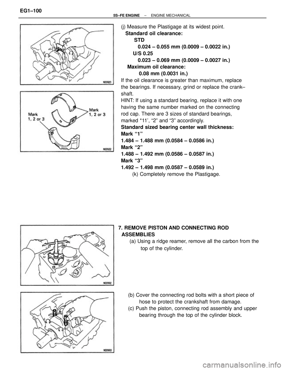
(j) Measure the Plastigage at its widest point.
Standard oil clearance:
STD
0.024 ± 0.055 mm (0.0009 ± 0.0022 in.)
U/S 0.25
0.023 ± 0.069 mm (0.0009 ± 0.0027 in.)
Maximum oil clearance:
0.08 mm (0.0031 in.)
If the oil clearance is greater than maximum, replace
the bearings. If necessary, grind or replace the crank±
shaft.
HINT: If using a standard bearing, replace it with one
having the same number marked on the connecting
rod cap. There are 3 sizes of standard bearings,
marked *11', ª2º and ª3º accordingly.
Standard sized bearing center wall thickness:
Mark ª1º
1.484 ± 1.488 mm (0.0584 ± 0.0586 in.)
Mark ª2º
1.488 ± 1.492 mm (0.0586 ± 0.0587 in.)
Mark ª3º
1.492 ± 1.498 mm (0.0587 ± 0.0589 in.)
(k) Completely remove the Plastigage.
(b) Cover the connecting rod bolts with a short piece of
hose to protect the crankshaft from damage.
(c) Push the piston, connecting rod assembly and upper
bearing through the top of the cylinder block. 7. REMOVE PISTON AND CONNECTING ROD
ASSEMBLIES
(a) Using a ridge reamer, remove all the carbon from the
top of the cylinder.
± 5S±FE ENGINEENGINE MECHANICALEG1±100
Page 193 of 4770
Backlash
Crankshaft x No. 1 balance shaft
Off±vehicle
On±vehicle
No. 1 balance shaft x No.2 balance shaft
at D mark
at E mark
at F mark
Spacer thickness
Engine moving control rod x No. 2 engine mounting bracketCamshaft timing pulley x Camshaft (For use with SST)
TORQUE SPECIFICATIONS
No. 2 engine mounting bracket x Cylinder blockBalance shaft housing bolt outer diameter
Engine moving control rod X Fender apronOil pump pulley x Oil pump drive 'shaft Cylinder head cover x Cylinder head
Cylinder head x Cylinder block (1 styCamshaft timing pulley x Camshaft No. 2 idler pulley x Cylinder block
No. 1 idler pulley x Cylinder heedCrankshaft pulley x Crankshaft Spark plug x Cylinder headEngine
balancerThrust clearance
Part tightened
± 5S±FE ENGINEENGINE MECHANICALEG1±143
Page 194 of 4770

No. 1 balance shaft housing x No. 2 balance shaft housing (1st)
No. 1 balance shaft housing x No. 2 balance shaft housing (2nd)
FR engine mounting insulator x Front suspension member
RR engine mounting insulator x Front suspension member Exhaust manifold stay x FR engine mounting insulator No. 1 air intake chamber stay x Intake manifold
RR engine mounting insulator x Cylinder block
FR engine mounting insulator x Cylinder block No. 1 air intake chamber stay x Cylinder head
No. 1 exhaust manifold stay x Cylinder block
Connecting rod cap x Connecting rod (2nd) Connecting rod cap x Connecting rod (1 st)
LH engine mounting insulator x Transaxle No. 1 exhaust manifold stay x WU ±TWC Water bypass pipe x Water pump cover
Fuel inlet hose x Fuel filter (Union bolt) No. 3 timing belt cover x Cylinder head
Intake manifold stay x Intake manifoldCamshaft bearing cap x Cylinder head
Intake manifold stay x Cylinder blockCylinder head x Cylinder block (2nd)
Rear oil seal retainer x Cylinder block Exhaust manifold stay x WU ±TWC
PS pump bracket x Cylinder block Main bearing cap x Cylinder block Generator bracket x Cylinder head
A/C compressor x Cylinder block Pulsation damper x Delivery pipe
Exhaust manifold x Cylinder head
Engine balancer x Cylinder block
Front exhaust pipe x WU ±TWC Spark plug tube x Cylinder head
Rear end plate x Cylinder block Throttle body x Intake manifold Intake manifold x Cylinder heedEngine hanger x Cylinder head
Drive plate x Crankshaft (A/T)Knock sensor x Cylinder block Delivery pipe x Cylinder head
PS pump x PS pump bracketWU±TWC x Exhaust manifold
Flywheel x Crankshaft (M/T) Water outlet x Cylinder headEGR valve x intake manifold
EGR pipe x Cylinder head
± 5S±FE ENGINEENGINE MECHANICALEG1±144
Page 223 of 4770

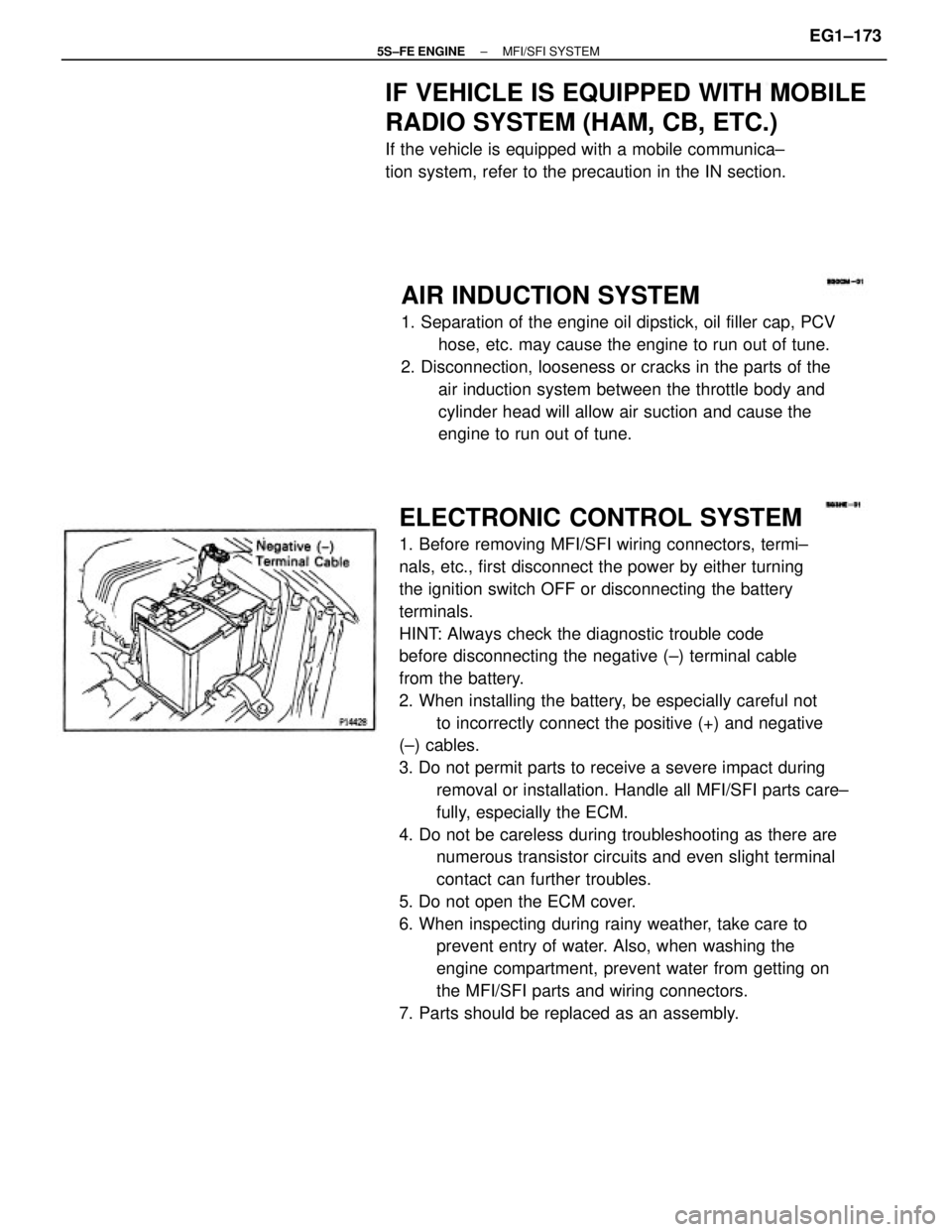
ELECTRONIC CONTROL SYSTEM
1. Before removing MFI/SFI wiring connectors, termi±
nals, etc., first disconnect the power by either turning
the ignition switch OFF or disconnecting the battery
terminals.
HINT: Always check the diagnostic trouble code
before disconnecting the negative (±) terminal cable
from the battery.
2. When installing the battery, be especially careful not
to incorrectly connect the positive (+) and negative
(±) cables.
3. Do not permit parts to receive a severe impact during
removal or installation. Handle all MFI/SFI parts care±
fully, especially the ECM.
4. Do not be careless during troubleshooting as there are
numerous transistor circuits and even slight terminal
contact can further troubles.
5. Do not open the ECM cover.
6. When inspecting during rainy weather, take care to
prevent entry of water. Also, when washing the
engine compartment, prevent water from getting on
the MFI/SFI parts and wiring connectors.
7. Parts should be replaced as an assembly.
AIR INDUCTION SYSTEM
1. Separation of the engine oil dipstick, oil filler cap, PCV
hose, etc. may cause the engine to run out of tune.
2. Disconnection, looseness or cracks in the parts of the
air induction system between the throttle body and
cylinder head will allow air suction and cause the
engine to run out of tune.
IF VEHICLE IS EQUIPPED WITH MOBILE
RADIO SYSTEM (HAM, CB, ETC.)
If the vehicle is equipped with a mobile communica±
tion system, refer to the precaution in the IN section.
± 5S±FE ENGINEMFI/SFI SYSTEMEG1±173
Page 317 of 4770
SERVICE SPECIFICATIONS
SERVICE DATA
TORQUE SPECIFICATIONS
Valve opening temperature
Valve lift
Water bypass pipe x Water pump cover
Radiator oil cooler x Radiator lower tank Water pump x Water pump cover
No.2 idler pulley x Cylinder block Water inlet x Water pump coverRelief valve opening pressure
Water pump x Cylinder blockCylinder block x Drain plug
Water inlet x Water pump
Radiator oil cooler pipe
Radiator support boltElectric
cooling fanRotating amperage
Part tightened Radiator cap
Plate height Thermostat
Radiator
± 5S±FE ENGINECOOLING SYSTEMEG1±267
Page 331 of 4770
2. INSTALL OIL SEAL
(a) Using SST and a hammer, tap in a new oil seal until its
surface is flush with the oil pump cover edge.
SST 09620±30010 (09627±30010, 09631±00020)
(b) Apply MP grease to the oil seal lip.
CRANKSHAFT FRONT OIL SEAL
REPLACEMENT
HINT: There are 2 methods (A and B) to replace the oil
seal which are as follows:
(b) Using SST and a hammer, tap in a new oil seal until its
surface is flush with the oil pump case edge.
SST 09226 ±10010
(c) Apply MP grease to the oil seal lip.
OIL PUMP OIL SEAL REPLACEMENT
1. REMOVE OIL SEAL
Using a screwdriver, pry out the oil seal.
REPLACE CRANKSHAFT FRONT OIL SEAL
A. If oil pump is removed from cylinder block:
(a) Using screwdriver and hammer, tap out the oil seal.
± 5S±FE ENGINELUBRICATION SYSTEMEG1±281