Page 3227 of 4770
DI05O±03
I00217
I00216
I00215
I00241
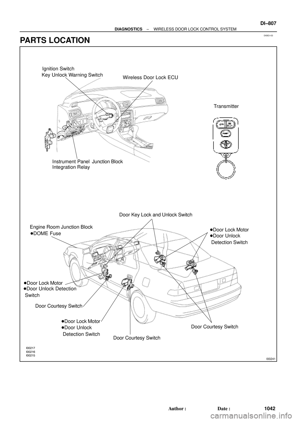
Ignition Switch
Key Unlock Warning Switch
Wireless Door Lock ECU
Transmitter
Instrument Panel Junction Block
Integration Relay
Engine Room Junction Block
�Door Lock Motor
�Door Unlock Detection
Switch
Door Courtesy Switch �DOME FuseDoor Key Lock and Unlock Switch
�Door Lock Motor
�Door Unlock
Detection Switch�Door Lock Motor
�Door Unlock
Detection Switch
Door Courtesy Switch
Door Courtesy Switch
± DIAGNOSTICSWIRELESS DOOR LOCK CONTROL SYSTEM
DI±807
1042 Author�: Date�:
PARTS LOCATION
Page 3231 of 4770
N14677
AB0117
N14690
I00242
LOCK
E(±)
+B(+)
± DIAGNOSTICSWIRELESS DOOR LOCK CONTROL SYSTEM
DI±811
1046 Author�: Date�:
INSPECTION PROCEDURE
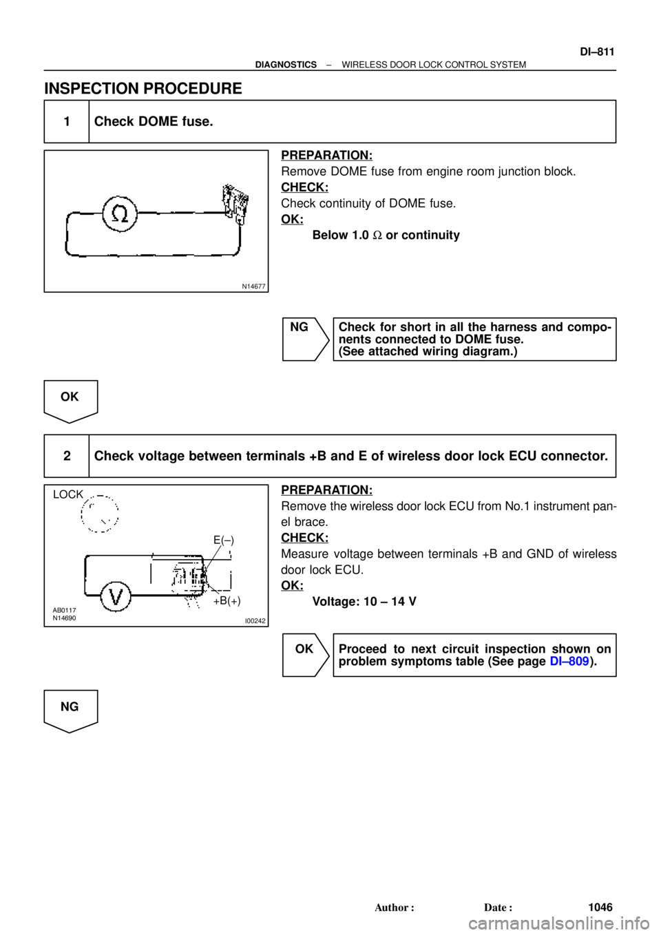
1 Check DOME fuse.
PREPARATION:
Remove DOME fuse from engine room junction block.
CHECK:
Check continuity of DOME fuse.
OK:
Below 1.0 W or continuity
NG Check for short in all the harness and compo-
nents connected to DOME fuse.
(See attached wiring diagram.)
OK
2 Check voltage between terminals +B and E of wireless door lock ECU connector.
PREPARATION:
Remove the wireless door lock ECU from No.1 instrument pan-
el brace.
CHECK:
Measure voltage between terminals +B and GND of wireless
door lock ECU.
OK:
Voltage: 10 ± 14 V
OK Proceed to next circuit inspection shown on
problem symptoms table (See page DI±809).
NG
Page 3250 of 4770

I00229
0.75 ± 0.1 sec.
1.25 ± 0.1 sec.
ON
OFF
Blinking Pattern Security only: DI±830
± DIAGNOSTICSTHEFT DETERRENT SYSTEM
1065 Author�: Date�:
4. CANCELLATION OF THEFT DETERRENT OPERA-
TION OR MODE
The theft deterrent operation of mode can be cancelled when
any of the following conditions is met.
No.ConditionCancel of OperationCancel of Mode
1Unlock front doors with the keyEffectiveEffective
2Unlock doors with remote keyless entryEffectiveEffective
3Insert key into ignition key cylinder and turn
it to ACC or ON positionEffectiveEffective
4About 1 minute passes after theft deterrent
operation beginsAutomatic stop *1±
5Unlock the luggage compartment door with
the key or keyless entry.UneffectiveEffective
6Unlock the luggage compartment door with
the keyless entry.UneffectiveEffective
7
If the system receives panic signal again or
unlock signal when the system is activated
by panic signal
Effective *2Uneffective
6If the system receives unlock signal when
the system is activated by panic signalEffectiveEffective
*1: The system is set to the theft deterrent mode again in
about 2 seconds after the operation stops, if all doors are
closed.
*2: The alarm caused by the panic signal malces the sys-
tem in the previous condition.
5. INDICATOR LIGHT (LED)
The indicator light functions as shown below according to the
system condition in the theft deterrent mode. It remains OFF in
the initial state.
System ConditionIndicator Light
During set preparation timeON
When the mode is set*OFF
When alarm is activatedON
When the system is temporally cancelled*OFF
*: The indicator flashes with the output from the immobiliser.
6. KEEPING POWER SUPPLY FUNCTION IN CASE OF
DOME FUSE OPEN
Even if the dome fuse blows open on the theft deterrent mode,
the system will keep working on the theft deterrent mode.
Page 3253 of 4770
DI06P±05
I00233
I00234
I00236
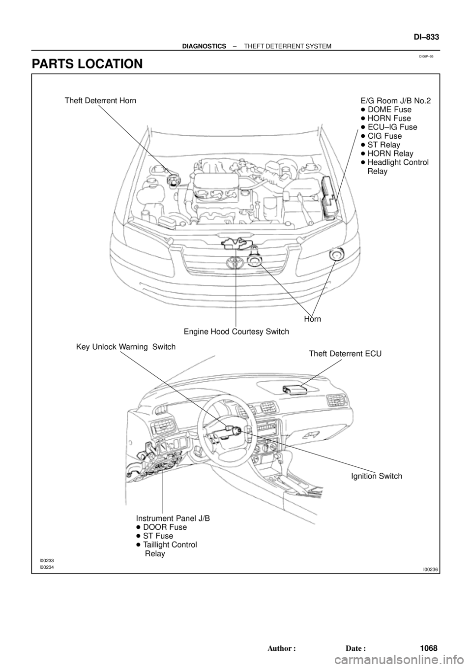
Theft Deterrent Horn
Horn
Engine Hood Courtesy SwitchE/G Room J/B No.2
� DOME Fuse
� HORN Fuse
� ECU±IG Fuse
� CIG Fuse
� ST Relay
� HORN Relay
� Headlight Control
Relay
Theft Deterrent ECU
Ignition Switch Key Unlock Warning Switch
Instrument Panel J/B
� DOOR Fuse
� ST Fuse
� Taillight Control
Relay
± DIAGNOSTICSTHEFT DETERRENT SYSTEM
DI±833
1068 Author�: Date�:
PARTS LOCATION
Page 3261 of 4770
I00268
I00269
I00275
E/G room J/B No.2:
Instrument panel J/B:DOME Fuse
DOOR Fuse
I01922E+B1
+B2
(+)
(±)
± DIAGNOSTICSTHEFT DETERRENT SYSTEM
DI±841
1076 Author�: Date�:
INSPECTION PROCEDURE
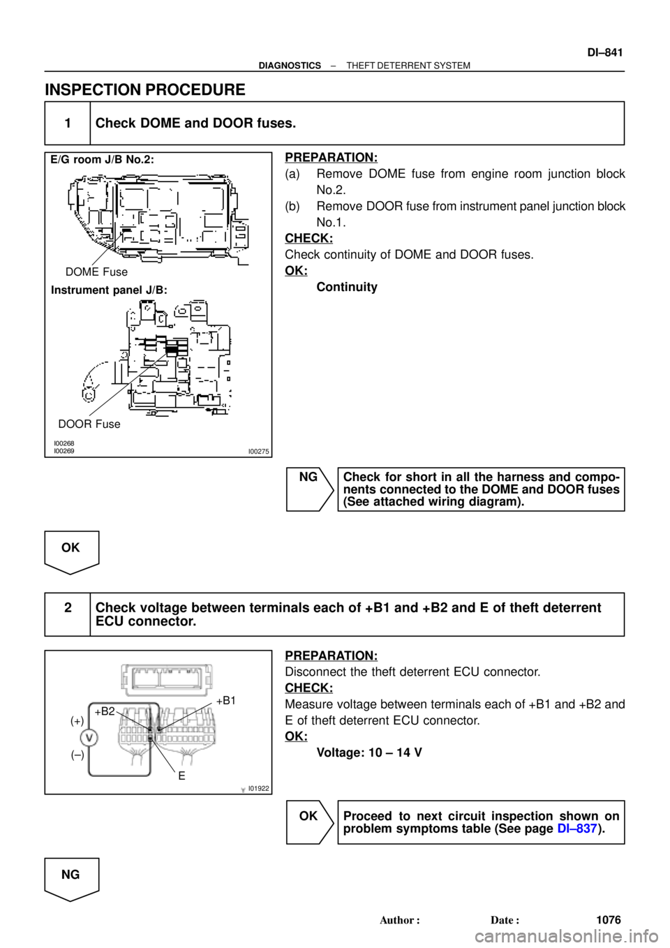
1 Check DOME and DOOR fuses.
PREPARATION:
(a) Remove DOME fuse from engine room junction block
No.2.
(b) Remove DOOR fuse from instrument panel junction block
No.1.
CHECK:
Check continuity of DOME and DOOR fuses.
OK:
Continuity
NG Check for short in all the harness and compo-
nents connected to the DOME and DOOR fuses
(See attached wiring diagram).
OK
2 Check voltage between terminals each of +B1 and +B2 and E of theft deterrent
ECU connector.
PREPARATION:
Disconnect the theft deterrent ECU connector.
CHECK:
Measure voltage between terminals each of +B1 and +B2 and
E of theft deterrent ECU connector.
OK:
Voltage: 10 ± 14 V
OK Proceed to next circuit inspection shown on
problem symptoms table (See page DI±837).
NG
Page 3264 of 4770
I00294
1
I00295
1 (+)
2 (±)
DI±844
± DIAGNOSTICSTHEFT DETERRENT SYSTEM
1079 Author�: Date�:
INSPECTION PROCEDURE
1 Check voltage between terminal 1 of theft deterrent horn connector and body
ground.
PREPARATION:
Remove the theft deterrent horn and disconnect the connector.
CHECK:
Measure voltage between terminal 1 of theft deterrent horn
connector and body ground.
OK:
Voltage: 10 ± 14 V
NG Check and repair harness and connector be-
tween HORN fuse and theft deterrent horn.
OK
2 Check theft deterrent horn.
CHECK:
Connect positive (+) lead to terminal 1 and negative (±) lead to
terminal 2 to theft deterrent horn connector.
OK:
Theft deterrent horn blows.
NG Replace theft deterrent horn.
OK
3 Check harness and connector between theft deterrent ECU and theft deterrent
horn (See page IN±29).
NG Check and repair harness or connector.
OK
Check and replace theft deterrent ECU.
Page 3272 of 4770
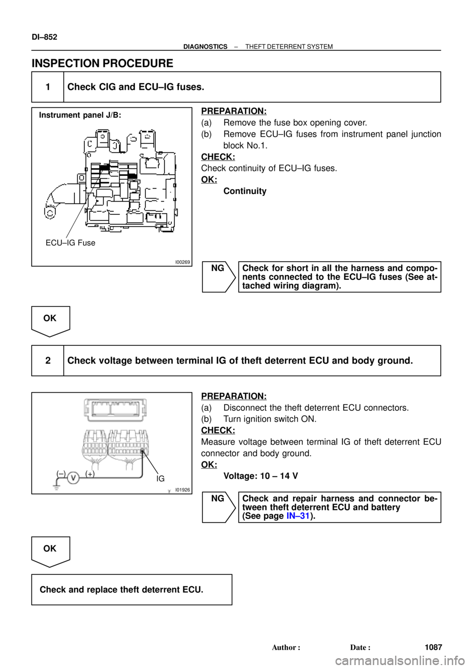
I00269
Instrument panel J/B:
ECU±IG Fuse
I01926
IG (+) (±)
DI±852
± DIAGNOSTICSTHEFT DETERRENT SYSTEM
1087 Author�: Date�:
INSPECTION PROCEDURE
1 Check CIG and ECU±IG fuses.
PREPARATION:
(a) Remove the fuse box opening cover.
(b) Remove ECU±IG fuses from instrument panel junction
block No.1.
CHECK:
Check continuity of ECU±IG fuses.
OK:
Continuity
NG Check for short in all the harness and compo-
nents connected to the ECU±IG fuses (See at-
tached wiring diagram).
OK
2 Check voltage between terminal IG of theft deterrent ECU and body ground.
PREPARATION:
(a) Disconnect the theft deterrent ECU connectors.
(b) Turn ignition switch ON.
CHECK:
Measure voltage between terminal IG of theft deterrent ECU
connector and body ground.
OK:
Voltage: 10 ± 14 V
NG Check and repair harness and connector be-
tween theft deterrent ECU and battery
(See page IN±31).
OK
Check and replace theft deterrent ECU.
Page 3295 of 4770

DI08I±08
± DIAGNOSTICSCRUISE CONTROL SYSTEM
DI±875
111 0 Author�: Date�:
DIAGNOSTIC TROUBLE CODE CHART
If a malfunction code is displayed during the DTC check, check the circuit listed for that code in the table
below and proceed to the appropriate page.
DTC No.
(See Page)Circuit InspectionTrouble Area
11, 15
(DI±881)Actuator Motor Circuit
�Actuator motor
�Harness or connector between cruise control ECU and
actuator motor
�Cruise control ECU
12
(DI±883)Actuator Magnetic Clutch Circuit
�STOP Fuse
�Stop light switch
�Actuator magnetic clutch
�Harness or connector between cruise control ECU and
actuator magnetic clutch, actuator magnetic clutch and body
ground
�Cruise control ECU
14
(DI±886)Actuator Mechanical Malfunction�Actuator motor (actuator lock: motor, arm)
�Cruise control ECU
21
(DI±888)Open in Vehicle Speed Sensor Circuit
�Combination meter
�Harness or connector between cruise control ECU and com-
bination meter, combination meter and vehicle speed sensor
�Vehicle speed sensor
�Cruise control ECU
23
(DI±891)Vehicle Speed Signal Abnormal�Vehicle speed sensor
�Cruise control ECU
32
(DI±892)Control Switch Circuit
�Cruise control switch
�Harness or connector between cruise control ECU and cruise
control switch, cruise control switch and body ground
�Cruise control ECU
41Cruise control ECU�Cruise control ECU
42Source voltage drop�Power source
51
(DI±895)Idle Signal Circuit
�Throttle position sensor
�Harness or connector between ECM and throttle position
sensor
�Harness or connector between cruise control ECU and ECM
�Cruise control ECU