Page 2407 of 4770
ELECTRIC COOLING FAN
CO±25
1633 Author�: Date�:
ELECTRIC COOLING FAN
ON±VEHICLE INSPECTION
1. CHECK COOLING FAN O")
B05939
CO03S±03
S04727
Disconnect
B05940
B05941
Ammeter
Battery
± COOLING (1MZ±FE)ELECTRIC COOLING FAN
CO±25
1633 Author�: Date�:
ELECTRIC COOLING FAN
ON±VEHICLE INSPECTION
1. CHECK COOLING FAN OPERATION WITH LOW
TEMPERATURE (Below 88°C (190°F))
(a) Turn the ignition switch ON.
(b) Check that the cooling fan stops.
If not, check the cooling fan relay and ECT switch, and check
for a separated connector or severed wire between the cooling
fan relay and ECT switch.
(c) Disconnect the No.1 ECT switch connector.
(d) Check that the cooling fan rotates.
If not, check the fuses, engine main relay, cooling fan relay,
cooling fan, and check for a short circuit between the cooling
fan relay and ECT switch.
(e) Reconnect the No.1 ECT switch connector.
2. CHECK COOLING FAN OPERATION WITH HIGH
TEMPERATURE (Above 98°C (208°F))
(a) Start the engine, and raise coolant temperature to above
98°C (208°F).
(b) Check that the cooling fan rotates.
If not, replace the No.1 ECT switch.
3. INSPECT NO.1 COOLING FAN
(a) Disconnect the cooling fan connector.
(b) Connect battery and ammeter to the cooling fan connec-
tor.
(c) Check that the cooling fan rotates smoothly, and check
the reading on the ammeter.
Standard amperage: 8.3 ± 11.3 A at 20°C (68°F)
(d) Reconnect the cooling fan connector.
Page 2426 of 4770

241 Author�: Date�:
(2) Connect the OBD II scan tool or TOYOTA hand±
held tester to DLC3 under the instrument panel low-
er pad.
(3) Turn the ignition switch ON a")
DI±6
± DIAGNOSTICSENGINE (5S±FE)
241 Author�: Date�:
(2) Connect the OBD II scan tool or TOYOTA hand±
held tester to DLC3 under the instrument panel low-
er pad.
(3) Turn the ignition switch ON and turn the OBD II scan
tool or TOYOTA hand±held tester switch ON.
(4) Use the OBD II scan tool or TOYOTA hand±held
tester to check the DTCs and freezed frame data
and note them down. (For operating instructions,
see the OBD II scan tool's instruction book.)
(5) See page DI±3 to confirm the details of the DTCs.
NOTICE:
�When simulating symptoms with an OBD II scan tool
(excluding TOYOTA hand±held tester) to check the
DTCs, use normal mode. For code on the DTC chart
subject to º2 trip detection logicº, perform the follow-
ing either action.
�Turn the ignition switch OFF after the symptom is
simulated the first time. Then repeat the simulation
process again. When the problem has been simulated
twice, the MIL lights up and the DTCs are recorded in
the ECM.
�Check the 1st trip DTC using Mode 7 (Continuous Test
Results) for SAE J1979.
(c) Clear the DTC.
The DTCs and freezed frame data will be erased by either
action.
(1) Operating the OBD II scan tool (complying with SAE
J1978) or TOYOTA hand±held tester to erase the
codes. (See the OBD II scan tool's instruction book
for operating instructions.)
(2) Disconnecting the battery terminals or EFI fuse.
NOTICE:
If the TOYOTA hand±held tester switches the ECM from
normal mode to check mode or vice±versa, or if the ignition
switch is turned from ON to ACC or OFF during check
mode, the DTCs and freezed frame data will be erased.
Page 2594 of 4770
A03026A03448
LOCK
BATT (+) w/o Immobiliser
w/ Immobiliser
BATT (+)
A00356
Engine Room J/B No.2
EFI Fuse
DI±174
± DIAGNOSTICSENGINE (5S±FE)
409 Author�: Date�:
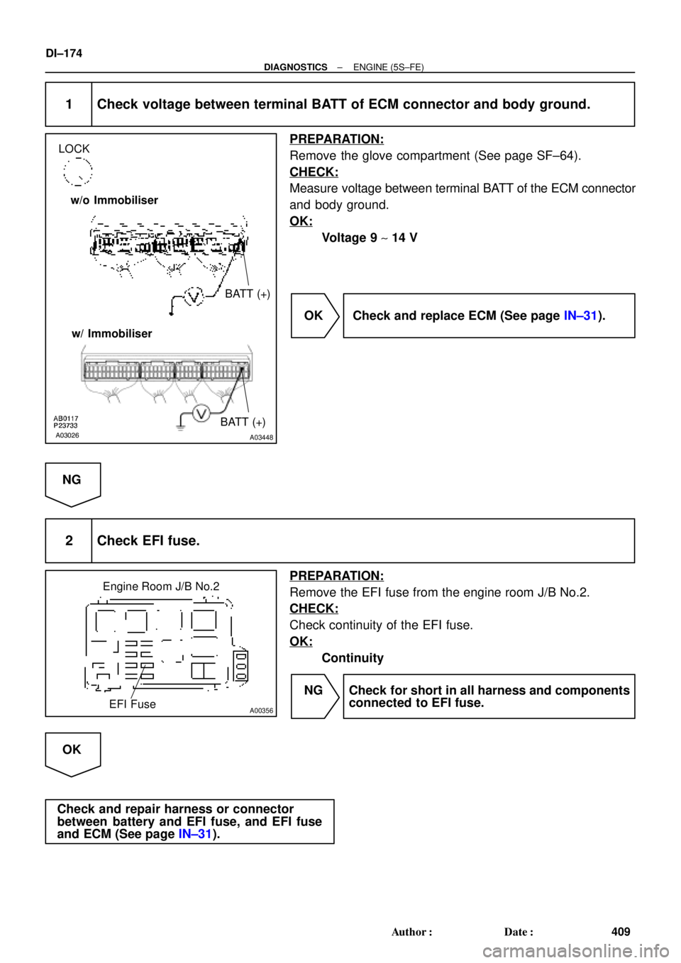
1 Check voltage between terminal BATT of ECM connector and body ground.
PREPARATION:
Remove the glove compartment (See page SF±64).
CHECK:
Measure voltage between terminal BATT of the ECM connector
and body ground.
OK:
Voltage 9 ~ 14 V
OK Check and replace ECM (See page IN±31).
NG
2 Check EFI fuse.
PREPARATION:
Remove the EFI fuse from the engine room J/B No.2.
CHECK:
Check continuity of the EFI fuse.
OK:
Continuity
NG Check for short in all harness and components
connected to EFI fuse.
OK
Check and repair harness or connector
between battery and EFI fuse, and EFI fuse
and ECM (See page IN±31).
Page 2601 of 4770
A00355
IGN Fuse
Instrument Panel J/B
± DIAGNOSTICSENGINE (5S±FE)
DI±181
416 Author�: Date�:
4 Check EFI fuse (See page DI±173, step 2).
NG Check for short in all harness and components
connected to EFI fuse.
OK
5 Check for open in harness and connector between EFI main relay (Marking: EFI)
and battery, and EFI main relay and ECM (See page IN±31).
NG Repair or replace harness or connector.
OK
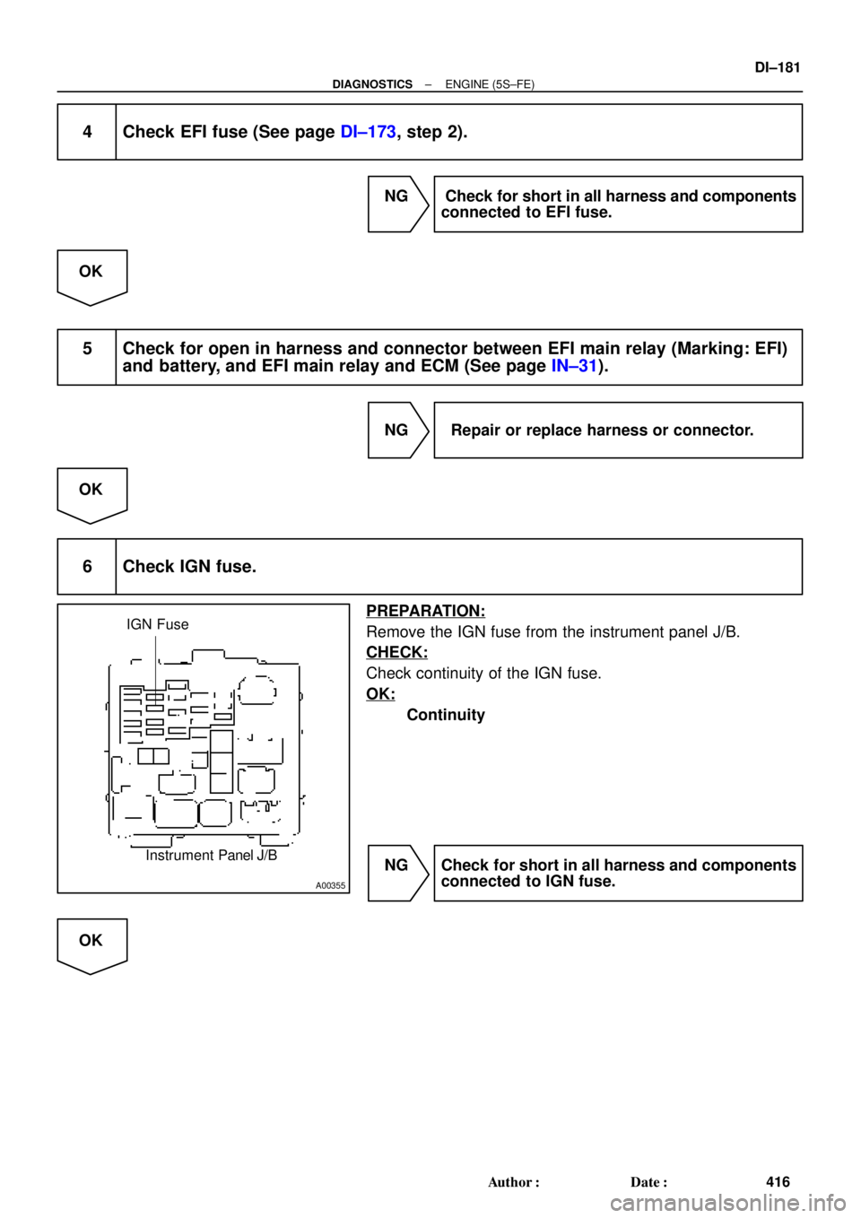
6 Check IGN fuse.
PREPARATION:
Remove the IGN fuse from the instrument panel J/B.
CHECK:
Check continuity of the IGN fuse.
OK:
Continuity
NG Check for short in all harness and components
connected to IGN fuse.
OK
Page 2620 of 4770

435 Author�: Date�:
(2) Connect the OBD II scan tool or TOYOTA hand±
held tester to DLC3 at the lower center of the instru-
ment panel.
(3) Turn the ignition s")
DI±200
± DIAGNOSTICSENGINE (1MZ±FE)
435 Author�: Date�:
(2) Connect the OBD II scan tool or TOYOTA hand±
held tester to DLC3 at the lower center of the instru-
ment panel.
(3) Turn the ignition switch ON and push the OBD II
scan tool or TOYOTA hand±held tester switch ON.
(4) Use the OBD II scan tool or TOYOTA hand±held
tester to check the DTC and freezed frame data and
note them down (For operating instructions, see the
OBD II scan tool's instruction book.).
(5) See page DI±197 to confirm the details of the DTC.
NOTICE:
�When simulating symptoms with an OBD II scan tool
(excluding TOYOTA hand±held tester) to check the
DTC, use normal mode. For code on the DTC chart
subject to º2 trip detection logicº, performe the fol-
lowing either action.
�Turn the ignition switch OFF after the symptom is
simulated the first time. Then repeat the simulation
process again. When the problem has been simulated
twice, the MIL lights up and the DTCs are recorded in
the ECM.
�Check the 1st trip DTC using Mode 7 (Continuous Test
Results) for SAE J1979.
(c) Clear the DTC.
The DTCs and freezed frame data will be erased by either
action.
�Operating the OBD II scan tool (complying
with SAE J1978) or TOYOTA hand±held tes-
ter to erase the codes. (See the OBD II scan
tool's instruction book for operating instruc-
tions.)
�Disconnecting the battery terminals or EFI
fuse.
NOTICE:
If the TOYOTA hand±held tester switches the ECM from
normal mode to check mode or vice±versa, or if the ignition
switch is turned from ON to ACC or OFF during check
mode, the DTCs and freezed frame data will be erased.
3. INSPECT DIAGNOSIS (Check Mode)
HINT:
TOYOTA hand±held tester only:
Compared to the normal mode, the check mode has an in-
creased sensitivity to detect malfunctions.
Furthermore, the same diagnostic items which are detected in
the normal mode can also be detected in the check mode.
Page 2787 of 4770
A02038
LOCK
BATT (+)
S04162
Engine Room J/B
EFI Fuse
± DIAGNOSTICSENGINE (1MZ±FE)
DI±367
602 Author�: Date�:
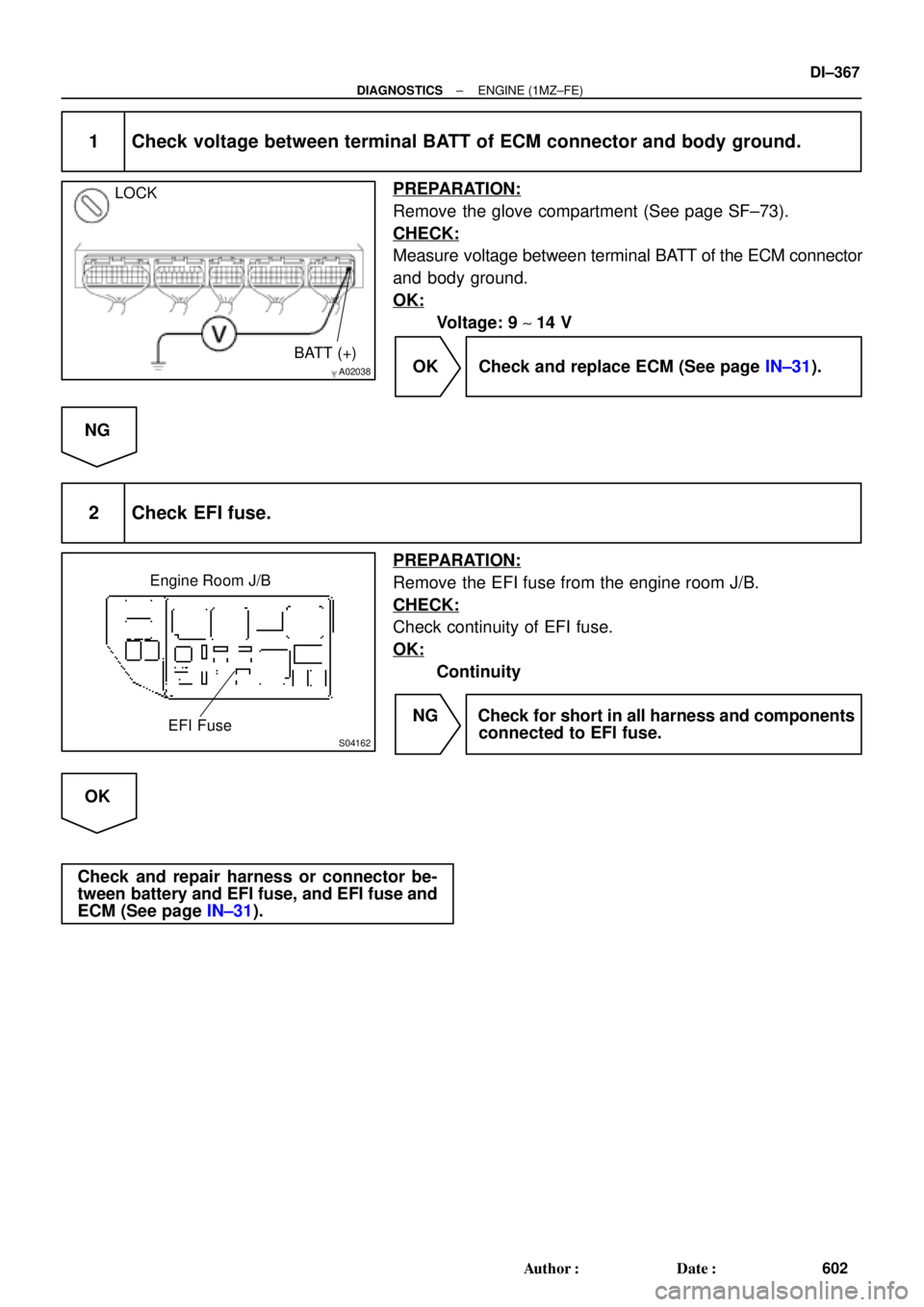
1 Check voltage between terminal BATT of ECM connector and body ground.
PREPARATION:
Remove the glove compartment (See page SF±73).
CHECK:
Measure voltage between terminal BATT of the ECM connector
and body ground.
OK:
Voltage: 9 ~ 14 V
OK Check and replace ECM (See page IN±31).
NG
2 Check EFI fuse.
PREPARATION:
Remove the EFI fuse from the engine room J/B.
CHECK:
Check continuity of EFI fuse.
OK:
Continuity
NG Check for short in all harness and components
connected to EFI fuse.
OK
Check and repair harness or connector be-
tween battery and EFI fuse, and EFI fuse and
ECM (See page IN±31).
Page 2791 of 4770
S04164
IGN Fuse
Instrument Panel J/B
± DIAGNOSTICSENGINE (1MZ±FE)
DI±371
606 Author�: Date�:
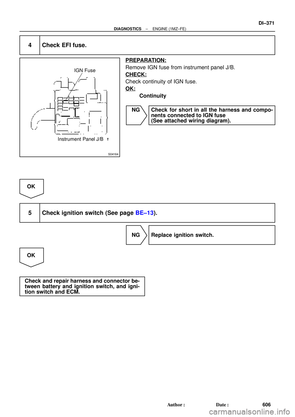
4 Check EFI fuse.
PREPARATION:
Remove IGN fuse from instrument panel J/B.
CHECK:
Check continuity of IGN fuse.
OK:
Continuity
NG Check for short in all the harness and compo-
nents connected to IGN fuse
(See attached wiring diagram).
OK
5 Check ignition switch (See page BE±13).
NG Replace ignition switch.
OK
Check and repair harness and connector be-
tween battery and ignition switch, and igni-
tion switch and ECM.
Page 2792 of 4770
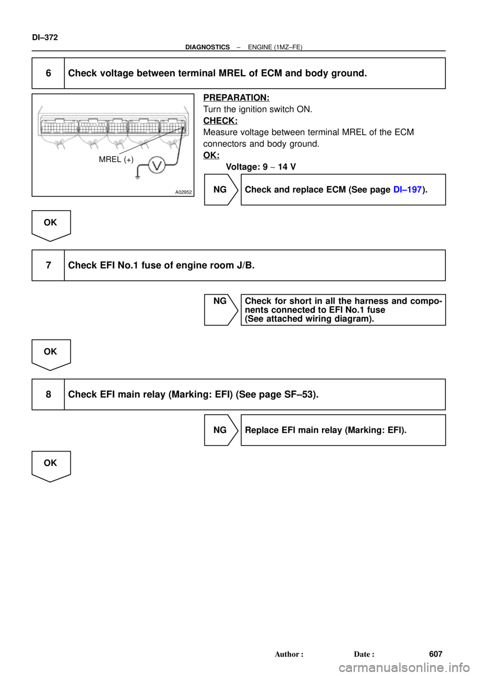
A02952
MREL (+)
DI±372
± DIAGNOSTICSENGINE (1MZ±FE)
607 Author�: Date�:
6 Check voltage between terminal MREL of ECM and body ground.
PREPARATION:
Turn the ignition switch ON.
CHECK:
Measure voltage between terminal MREL of the ECM
connectors and body ground.
OK:
Voltage: 9 ~ 14 V
NG Check and replace ECM (See page DI±197).
OK
7 Check EFI No.1 fuse of engine room J/B.
NG Check for short in all the harness and compo-
nents connected to EFI No.1 fuse
(See attached wiring diagram).
OK
8 Check EFI main relay (Marking: EFI) (See page SF±53).
NG Replace EFI main relay (Marking: EFI).
OK