Page 2201 of 4770

I03355I03355
16 CD Player CD CANNOT BE INSERTED
Is CD already inserted? Eject CD.
Is auto search button of radio operating normally? Is +B applied to CD player?Radio assembly
faulty.
Check that GND wire harness side
to CD player is OK?
CD player faulty.
Check that RAD No.1 fuse is OK?
Is +B applied to power amplifier?
Check that GND (wire harness side) to radio assembly is OK?
Radio assembly faulty.Replace fuse.
+B wire harness faulty. Ye s
No
Ye s
Ye s
Ye sNo
NoNG
OK
OK
OKNG
NG No
17 CD Player CD INSERTED, BUT NO POWER
Does radio operate normally?Is ACC applied to CD player?Radio assembly
faulty.
CD player faulty.
Check that RAD No.1 and No.2 fuse is OK?
Is ACC and +B, +B2 applied to power amplifier?
Is ACC and +B, +B2 applied to radio assembly?Replace fuse.
ACC and +B, +B2 wire harness faulty.
Power amplifier faulty.
Radio assembly faulty.Ye s
Ye s
Ye s
Ye sNoNo
No
No NG
OK
� Radio±CD Player Unit (Built±in Power Amplifier)
� Radio±CD Player Unit (Separate Power Amplifier)
� Radio±Tape Player ± CD Player (Separate Power Amplifier) � Radio±CD Player Unit (Built±in Power Amplifier)
� Radio±CD Player Unit (Separate Power Amplifier)
� Radio±Tape Player ± CD Player (Separate Power Amplifier)
± BODY ELECTRICALAUDIO SYSTEM
BE±107
2327 Author�: Date�:
Page 2204 of 4770

I03358
Does radio operate normally?
Is hiss noise produced by non±functioning speaker?
Does continuity exist in speaker wire harness?
Temporarily install another speaker.
Function OK.
Power amplifier faulty.
Recheck system after repair.CD player.
Radio assembly faulty.
Recheck system after repair.
Speaker wire harness faulty.
Speaker faulty. Ye sYe s
Ye s
Ye s No
No
NoNo 21 CD Player EITHER SPEAKER DOES NOT WORK
22 CD Player CD WILL NOT BE EJECTED
Is auto search button of radio
operating normally?Is +B applied to CD player?Radio assembly
faulty.
CD player faulty. Ye s N o
Ye s
No
Check that RAD No.1 fuse is OK?Replace fuse.
Is +B and +B2 applied to power amplifier?
Is +B and +B2 applied to radio assembly?
Radio assembly faulty.+B wire harness faulty.
Power amplifier faulty. OK
Ye s
Ye sNG
No
No � Radio±CD Player Unit (Built±in Power Amplifier)
� Radio±CD Player Unit (Separate Power Amplifier)
� Radio±Tape Player ± CD Player (Separate Power Amplifier)
� Radio±CD Player Unit (Built±in Power Amplifier)
� Radio±CD Player Unit (Separate Power Amplifier)
� Radio±Tape Player ± CD Player (Separate Power Amplifier) BE±110
± BODY ELECTRICALAUDIO SYSTEM
2330 Author�: Date�:
Page 2208 of 4770
BE0AZ±05
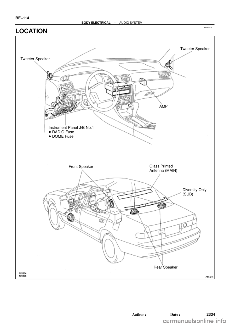
Z19489
Tweeter SpeakerTweeter Speaker
AMP
Instrument Panel J/B No.1
� RADIO Fuse
� DOME Fuse
Front SpeakerGlass Printed
Antenna (MAIN)
Diversity Only
(SUB)
Rear Speaker BE±114
± BODY ELECTRICALAUDIO SYSTEM
2334 Author�: Date�:
LOCATION
Page 2211 of 4770

Power Source
(System Operation)
Power Source
(Display Operation)Connector
(Clock Side)
(Wire Harness Side)")
BE0B1±02
Z04388
E
ILL
B
ACC
BE1847 e±4±2±D e±4±1±D
Ground
Power Source
(Illumination)
Power Source
(System Operation)
Power Source
(Display Operation)Connector
(Clock Side)
(Wire Harness Side)
1 2 3 44 123
V04421
1 CLOCK WILL NOT OPERATE
(Clock Side)(Wire Harness Side)
B+
GND
e±4±2±D e±4±1±D
(a) Check that the battery positive voltage is 10 ± 16 V.
If voltage is not as specified, replace the battery.
(b) Check that the DOME fuse is not blown.
If the fuse is blown, replace the fuse and check for short circuit.
(c) Troubleshoot the clock as follows.
HINT: Inspect the connector on the wire harness side.
Is there battery positive voltage between terminal
B+ and body ground?
Does continuity exist between terminal GND
and body ground.
Replace clock.Ye s
Ye sOpen or short circuit in wire harness between
terminal GND and body ground.
Open circuit in wire harness between terminal
GND and body ground. No
No
± BODY ELECTRICALCLOCK
BE±117
2337 Author�: Date�:
CLOCK
TROUBLESHOOTING
HINT:
Troubleshoot the clock according to the table below.
Clock will not operate1
Clock loses or gains time2
± 1.5 seconds / day
Page 2221 of 4770
BE0B3±06
I02682
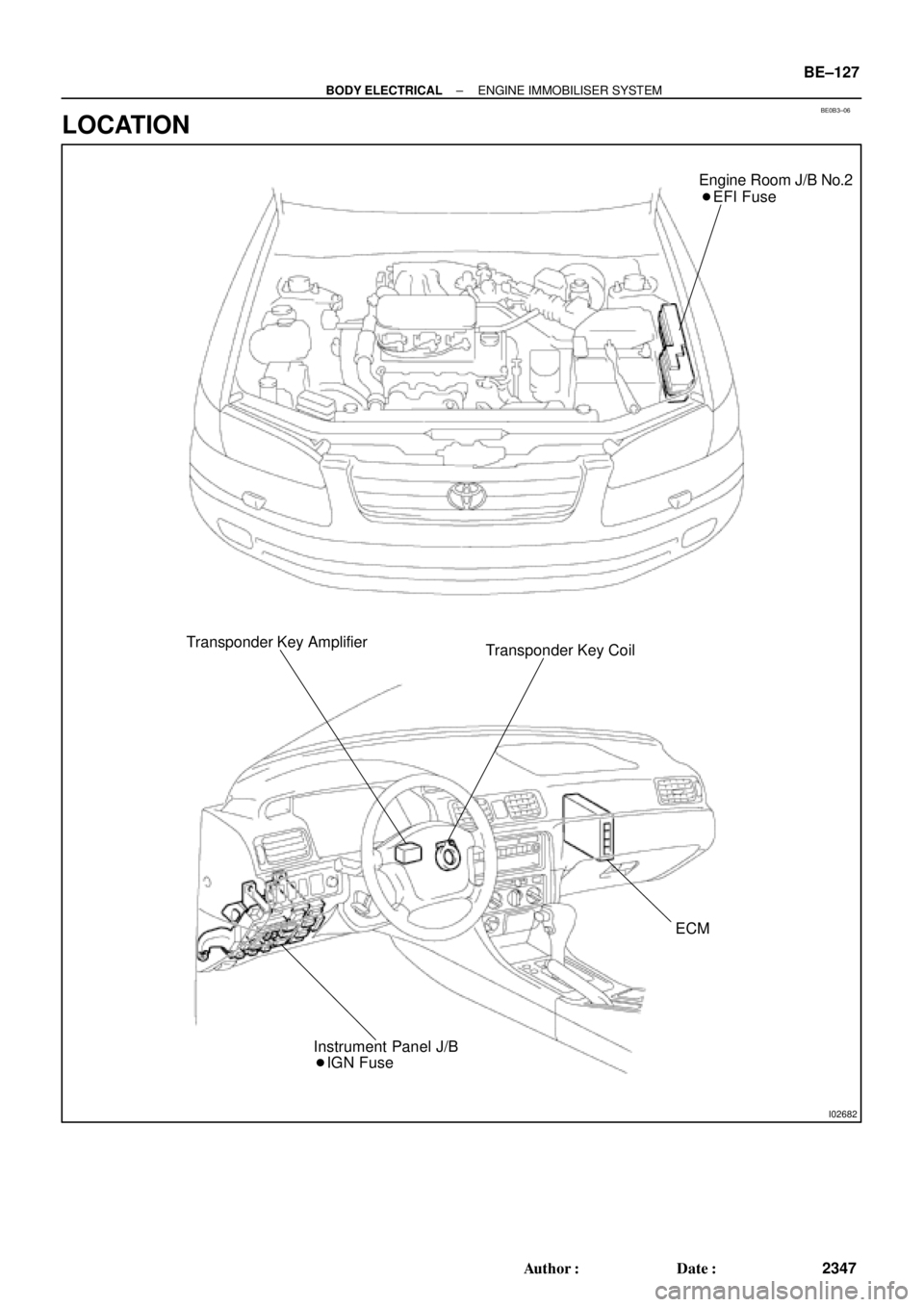
Engine Room J/B No.2
� EFI Fuse
Transponder Key Amplifier
Transponder Key Coil
ECM
� IGN Fuse Instrument Panel J/B
± BODY ELECTRICALENGINE IMMOBILISER SYSTEM
BE±127
2347 Author�: Date�:
LOCATION
Page 2296 of 4770

Z18811
Maintenance±Free Battery
Type A
Type B
Blue White Red
OK Charging
NecessaryInsufficient
Water
GREEN EYE DARK EYECLEAR EYE or
CHARGED DISCHARGED ADD WATERLIGHT YELLOW
Z00015
Z00038
DENSOBorroughs
CH0086
CORRECTWRONG CH±2
± CHARGING (5S±FE)CHARGING SYSTEM
1749 Author�: Date�:
HINT:
Check the indicator as shown in the illustration.
4. CHECK BATTERY TERMINALS, FUSIBLE LINK AND
FUSES
(a) Check that the battery terminals are not loose or cor-
roded.
If the terminals are corroded, clean the terminals.
(b) Check the fusible link, H±fuses, M±fuse and fuses for
continuity.
5. INSPECT DRIVE BELTS
(a) Visually check the drive belt for excessive wear, frayed
cords etc.
If any defect has been found, replace the drive belt.
HINT:
Cracks on the rib side of a drive belt are considered acceptable.
If the drive belt has chunks missing from the ribs, it should be
replaced.
(b) Using a belt tension gauge, measure the belt tension.
Belt tension gauge:
DENSO BTG±20 (95506±00020)
Borroughs No. BT±33±73F
Drive belt tension:
w/ A/C New belt
Used belt165 ± 25 lbf
110 ± 10 lbf
w/o A/C New belt
Used belt125 ± 25 lbf
95 ± 20 lbf
If the belt tension is not as specified, adjust it.
HINT:
�ºNew beltº refers to a belt which has been used less than
5 minutes on a running engine.
�ºUsed beltº refers to a belt which has been used on a run-
ning engine for 5 minutes or more.
�After installing a belt, check that it fits properly in the
ribbed grooves.
�Check with your hand to confirm that the belt has not
slipped out of the groove on the bottom of the pulley.
Page 2312 of 4770

Z18811
Maintenance±Free Battery
Type A
Type B
Blue White Red
OK Charging
NecessaryInsufficient
Water
GREEN EYE DARK EYECLEAR EYE or
CHARGED DISCHARGED ADD WATERLIGHT YELLOW
Z00015
Z00038
DENSO
Borroughs
CH0086
CORRECT WRONG CH±2
± CHARGING (1MZ±FE)CHARGING SYSTEM
1765 Author�: Date�:
HINT:
Check the indicator as shown in the illustration.
4. CHECK BATTERY TERMINALS, FUSIBLE LINK AND
FUSES
(a) Check that the battery terminals are not loose or cor-
roded.
If the terminals are corroded, clean the terminals.
(b) Check the fusible link, H±fuses, M±fuse and fuses for
continuity.
5. INSPECT DRIVE BELTS
(a) Visually check the drive belt for excessive wear, frayed
cords etc.
If any defect has been found, replace the drive belt.
HINT:
Cracks on the rib side of a drive belt are considered acceptable.
If the drive belt has chunks missing from the ribs, it should be
replaced.
(b) Using a belt tension gauge, measure the belt tension.
Belt tension gauge:
DENSO BTG±20 (95506±00020)
Borroughs No. BT±33±73F
Drive belt tension:
New belt175 ± 5 lbf
Used belt115 ± 20 lbf
If the belt tension is not as specified, adjust it.
HINT:
�ºNew beltº refers to a belt which has been used less than
5 minutes on a running engine.
�ºUsed beltº refers to a belt which has been used on a run-
ning engine for 5 minutes or more.
�After installing a belt, check that it fits properly in the
ribbed grooves.
�Check with your hand to confirm that the belt has not
slipped out of the groove on the bottom of the pulley.
Page 2372 of 4770

(+) (+)
(±)
Battery Ammeter CO±24
± COOLING (5S±FE)ELECTRIC COOLING FAN
1598 Author�: Date�:
ELECTRIC COOLING FAN")
S05959
CO06N±03
S05953
ECT Switch
Connector
Z19282
No.1
No.2Battery
Ammeter (±)
(+) (+)
(±)
Battery Ammeter CO±24
± COOLING (5S±FE)ELECTRIC COOLING FAN
1598 Author�: Date�:
ELECTRIC COOLING FAN
ON±VEHICLE INSPECTION
1. CHECK COOLING FAN OPERATION WITH LOW TEM-
PERATURE (Below 83°C (181°F))
(a) Turn the ignition switch ON.
(b) Check that the cooling fan stops.
If not, check the cooling fan relay and ECT switch, and check
for a separated connector or severed wire between the cooling
fan relay and ECT switch.
(c) Disconnect the ECT switch connector.
(d) Check that the cooling fan rotates.
If not, check the fan main relay, cooling fan relay, cooling fan,
fuses, and check for short circuit between the cooling fan relay
and ECT switch.
(e) Reconnect the ECT switch connector.
2. CHECK COOLING FAN OPERATION WITH HIGH TEM-
PERATURE (Above 93°C (199°F))
(a) Start the engine, and raise coolant temperature to above
93°C (199°F).
(b) Check that the cooling fan rotates.
If not, replace the ECT switch.
3. INSPECT COOLING FANS
(a) Disconnect the cooling fan connector.
(b) Connect battery and ammeter to the connector.
(c) Check that the cooling fan rotates smoothly, and check
the reading on the ammeter.
Standard amperage: 4.9 ± 8.5 A
(d) Reconnect the cooling fan connector.