Page 2979 of 4770
F00073
ECU±IG
Instrument
Panel J/BECU±IG
Instrument
Panel J/BECU±IG
Instrument
Panel J/B
± DIAGNOSTICSANTI±LOCK BRAKE SYSTEM (BOSCH Made)
DI±559
794 Author�: Date�:
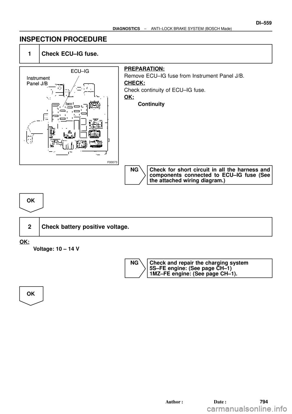
INSPECTION PROCEDURE
1 Check ECU±IG fuse.
PREPARATION:
Remove ECU±IG fuse from Instrument Panel J/B.
CHECK:
Check continuity of ECU±IG fuse.
OK:
Continuity
NG Check for short circuit in all the harness and
components connected to ECU±IG fuse (See
the attached wiring diagram.)
OK
2 Check battery positive voltage.
OK:
Voltage: 10 ± 14 V
NG Check and repair the charging system
5S±FE engine: (See page CH±1)
1MZ±FE engine: (See page CH±1).
OK
Page 2984 of 4770
F00067
ON
IG1
(+) (±)
GND
DI±564
± DIAGNOSTICSANTI±LOCK BRAKE SYSTEM (BOSCH Made)
799 Author�: Date�:
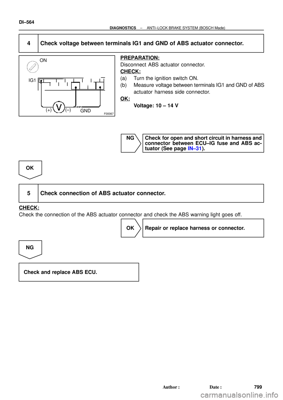
4 Check voltage between terminals IG1 and GND of ABS actuator connector.
PREPARATION:
Disconnect ABS actuator connector.
CHECK:
(a) Turn the ignition switch ON.
(b) Measure voltage between terminals IG1 and GND of ABS
actuator harness side connector.
OK:
Voltage: 10 ± 14 V
NG Check for open and short circuit in harness and
connector between ECU±IG fuse and ABS ac-
tuator (See page IN±31).
OK
5 Check connection of ABS actuator connector.
CHECK:
Check the connection of the ABS actuator connector and check the ABS warning light goes off.
OK Repair or replace harness or connector.
NG
Check and replace ABS ECU.
Page 2985 of 4770
F00096
J/C
J4 D
ABS 7
C
R±LC10
1D
GAUGE
A6 4
DLC2ECU
Instrument
Panel J/BABS
Warning
Light
210
IG312
C10
DR±L R±L
WA 21
14 R±LJ/C
J29
C
C R±L
R±LR±L
IK3
± DIAGNOSTICSANTI±LOCK BRAKE SYSTEM (BOSCH Made)
DI±565
800 Author�: Date�:
ABS Warning Light Circuit
CIRCUIT DESCRIPTION
If the ECU detects any trouble, it lights the ABS warning light while at the same time prohibiting ABS control.
At this time, the ECU records a DTC in memory.
Connect terminals Tc and E
1 of the DLC1 or DLC2 to make the ABS warning light blink and output the DTC.
WIRING DIAGRAM
INSPECTION PROCEDURE
Troubleshoot in accordance with the chart below for each trouble symptom
ABS warning light does not light upGo to step 1
ABS warning light remains onGo to step 2
1 Check ABS warning light.
See combination meter troubleshooting on page BE±2.
NG Repair bulb or combination meter assembly.
OK
Check for open circuit in harness and connector between GAUGE fuse, DLC2 and ABS ECU
(See page IN±31).
DI048±08
Page 3019 of 4770
F00073
ECU±IGECU±IG
Instrument
Panel J/BECU±IG
± DIAGNOSTICSABS & TRACTION CONTROL SYSTEM
DI±599
834 Author�: Date�:
INSPECTION PROCEDURE
1 Check ECU±IG fuse.
PREPARATION:
Remove ECU±IG fuse from Instrument Panel J/B.
CHECK:
Check continuity of ECU±IG fuse.
OK:
Continuity
NG Check for short in all the harness and compo-
nents connected to ECU±IG fuse (See attached
wiring diagram).
OK
2 Check battery positive voltage.
OK:
Voltage: 10 ± 14 V
NG Check and repair the charging system
5S±FE engine: (See page CH±1)
1MZ±FE engine: (See page CH±1).
OK
Page 3030 of 4770
DI±610
± DIAGNOSTICSABS & TRACTION CONTROL SYSTEM
845 Author�: Date�:
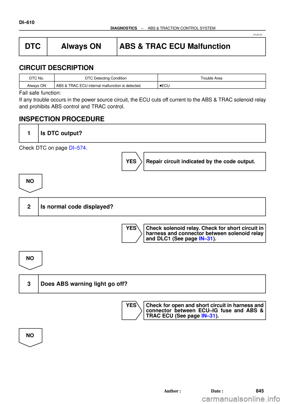
DTC Always ON ABS & TRAC ECU Malfunction
CIRCUIT DESCRIPTION
DTC No.DTC Detecting ConditionTrouble Area
Always ONABS & TRAC ECU internal malfunction is detected.�ECU
Fail safe function:
If any trouble occurs in the power source circuit, the ECU cuts off current to the ABS & TRAC solenoid relay
and prohibits ABS control and TRAC control.
INSPECTION PROCEDURE
1 Is DTC output?
Check DTC on page DI±574.
YES Repair circuit indicated by the code output.
NO
2 Is normal code displayed?
YES Check solenoid relay. Check for short circuit in
harness and connector between solenoid relay
and DLC1 (See page IN±31).
NO
3 Does ABS warning light go off?
YES Check for open and short circuit in harness and
connector between ECU±IG fuse and ABS &
TRAC ECU (See page IN±31).
NO
DI1JQ±03
Page 3057 of 4770

DI1B1±08
H01357
C18
C17C19
287 8 9 10 16 17
18A B12 3 4 5 6
11 12 15 14 13
AABB
19 20 21 22 23 24 25 26 27 1 2 3 4 5 6
7 8 9 10 11 121 2 3 4 5 6
7 8 9 10 11 12
± DIAGNOSTICSSUPPLEMENTAL RESTRAINT SYSTEM
DI±637
872 Author�: Date�:
TERMINALS OF ECU
No.SymbolTerminal Name
A±Electrical Connector Check Mechanism
B±Electrical Connector Check Mechanism
C18 ± 3LASRS Warning Light
C18 ± 5IG2Power Source (IGN Fuse)
C18 ± 6ACCPower Source (CIG Fuse)
C18 ± 9SR+Front Airbag Sensor (RH)
C18 ± 10P+Squib (Passenger)
C18 ± 11P±Squib (Passenger)
C18 ± 12SILDiagnosis
C18 ± 13D±Squib (Driver)
C18 ± 14D+Squib (Driver)
C18 ± 15SL+Front Airbag Sensor (LH)
C18 ± 19TcDiagnosis
C18 ± 20SR±Front Airbag Sensor (RH)
C18 ± 26SL±Front Airbag Sensor (LH)
C18 ± 27E1Ground
C18 ± 28E2Ground
C17 ± 1PL±Squib (Seat Belt Pretensioner, LH)
C17 ± 2PL+Squib (Seat Belt Pretensioner, LH)
C17 ± 5SFL+Squib (Side, LH)
C17 ± 6SFL±Squib (Side, LH)
C17 ± 7VUPLSide Airbag Sensor (LH)
C17 ± 9SSL+Side Airbag Sensor (LH)
C17 ± 10FSLSide Airbag Sensor (LH)
C17 ± 12ESLSide Airbag Sensor (LH)
Page 3212 of 4770

CIRCUIT DES")
N14677
Fuse
DI±792
± DIAGNOSTICSSUPPLEMENTAL RESTRAINT SYSTEM
1027 Author�: Date�:
SRS Warning Light Circuit Malfunction (Does not light up, when
ignition switch is turned to ACC or ON.)
CIRCUIT DESCRIPTION
The SRS warning light is located on the combination meter.
When the SRS is normal, the SRS warning light lights up for approx. 6 seconds after the ignition switch is
turned from LOCK position to ACC or ON position, and then turns off automatically.
If there is a malfunction in the SRS, the SRS warning light lights up to inform the driver of the abnormality.
When terminals Tc and E1 of the DLC1 are connected, the DTC is displayed by blinking the SRS warning
light.
WIRING DIAGRAM
See page DI±790.
INSPECTION PROCEDURE
1 Check ECU±B Fuse.
PREPARATION:
Remove ECU±B fuse.
CHECK:
Check continuity of ECU±B fuse.
OK:
Continuity
HINT:
�Fuse may be burnt out even if it appears to be OK during
visual inspection.
�If fuse is OK, install it.
NG Go to step 5.
OK
2 Prepare for inspection. (See step 1 on page DI±787)
DI1BP±08
Page 3215 of 4770
± DIAGNOSTICSSUPPLEMENTAL RESTRAINT SYSTEM
DI±795
1030 Author�: Date�:
5 Is new ECU±B fuse burnt out again?
NO Using simulation method, reproduce malfunc-
tion symptoms. (See page IN±21)
YES
Check harness between ECU±B fuse and
SRS warning light.