Page 4100 of 4770
SF0EN±03
S05331
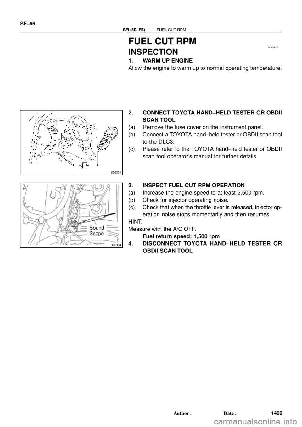
S05304
Sound
Scope SF±66
± SFI (5S±FE)FUEL CUT RPM
1499 Author�: Date�:
FUEL CUT RPM
INSPECTION
1. WARM UP ENGINE
Allow the engine to warm up to normal operating temperature.
2. CONNECT TOYOTA HAND±HELD TESTER OR OBDII
SCAN TOOL
(a) Remove the fuse cover on the instrument panel.
(b) Connect a TOYOTA hand±held tester or OBDII scan tool
to the DLC3.
(c) Please refer to the TOYOTA hand±held tester or OBDII
scan tool operator's manual for further details.
3. INSPECT FUEL CUT RPM OPERATION
(a) Increase the engine speed to at least 2,500 rpm.
(b) Check for injector operating noise.
(c) Check that when the throttle lever is released, injector op-
eration noise stops momentarily and then resumes.
HINT:
Measure with the A/C OFF.
Fuel return speed: 1,500 rpm
4. DISCONNECT TOYOTA HAND±HELD TESTER OR
OBDII SCAN TOOL
Page 4106 of 4770
FUEL PUMP
1505 Author�: Date�:
FUEL PUMP
ON±VEHICLE INSPECTION
1. CHECK FUEL PUMP OPERATION
(a) Connect")
S05358
TOYOTA
Hand Held TesterSF079±04
S05353
S05359
Fuel Tube Connector
SF±6
± SFI (1MZ±FE)FUEL PUMP
1505 Author�: Date�:
FUEL PUMP
ON±VEHICLE INSPECTION
1. CHECK FUEL PUMP OPERATION
(a) Connect a TOYOTA hand±held tester to the DLC3.
(b) Turn the ignition switch ON and push the TOYOTA hand±
held tester main switch ON.
NOTICE:
Do not start the engine.
(c) Select the ACTIVE TEST mode on the TOYOTA hand±
held tester.
(d) Please refer to the TOYOTA hand±held tester operator's
manual for further details.
(e) If you have no TOYOTA hand±held tester, connect the
positive (+) and negative (±) leads from the battery to the
fuel pump connector. (See step 7)
(f) Check that there is pressure in the fuel inlet hose from the
fuel filter.
HINT:
If there is fuel pressure, you will hear the sound of fuel flowing.
If there is no pressure, check these parts:
Fusible link
Fuses
EFI main relay
Fuel pump
ECM
Wiring connections
(g) Turn the ignition switch OFF.
(h) Disconnect the TOYOTA hand±held tester from the
DLC3.
2. CHECK FUEL PRESSURE
(a) Check the battery positive voltage is above 12 V.
(b) Disconnect the negative (±) terminal cable from the bat-
tery.
(c) Purchase the new No.1 fuel pipe and take out the fuel
tube connector from its pipe.
Part No. 23801±20041
Page 4532 of 4770

Toyota Supports ASE CertificationPage 1 of 23
EG003-02Title:
READINESS MONITOR DRIVE PATTERNS
Models:
All '96 ± '02
Technical Service
BULLETIN
March 29, 2002
TSB REVISION NOTICE:
The information updated in this TSB is red
and underlined.
The On±Board Diagnostic (OBDII) system is designed to monitor the performance of
emission±related components and report any detected abnormalities in the form of
Diagnostic Trouble Codes (DTCs). Since the various components need to be monitored
during different driving conditions, the OBDII system is designed to run separate
monitoring programs called Readiness Monitors. Many state Inspection and
Maintenance (I/M) programs require that vehicles complete their Readiness Monitors
prior to beginning an emissions test.
The current status of the Readiness Monitors can be seen by using the Toyota Diagnostic
Tester with version 9.0 software (or newer), or a generic OBDII Scantool.
To view the Readiness Monitor status using the Toyota Diagnostic Tester, select ªMonitor
Statusº from the Enhanced OBDII Menu.
A status of ªcompleteº indicates that the necessary conditions have been met to run the
performance tests for the related Readiness Monitor.
The Readiness Monitor will be reset to ªincompleteº if:
�ECU has lost power (battery or fuse).
�DTCs have been cleared.
�The conditions for running the Readiness Monitor have not been met.
In the event that any Readiness Monitor shows ªincomplete,º follow the appropriate
Readiness Monitor Drive Pattern to change the readiness status to ªcomplete.º
Refer to the Readiness Monitor Drive Pattern Application Table to determine which
drive pattern should be followed.
SECTIONPAGE(S)
Readiness Monitor Drive Pattern Application Tables3±9
Readiness Monitor Drive Patterns
1EGR Monitor (All Except 1FZ±FE Engine)10
2EGR Monitor (For 1FZ±FE Engine)11
3Catalyst Monitor (O2S Type)12
4Catalyst Monitor (AF Sensor Type)13
5EVAP Monitor (Internal Pressure Monitor/Non±Intrusive Type)14±15
6EVAP Monitor (Vacuum Pressure Monitor/Intrusive Type)16±17
7EVAP Monitor (Without Leak Detection)18
8EVAP Monitor (For Prius)19±20
9Oxygen Sensor Monitor (Front and Rear O2S System)21
10Oxygen/AF Sensor Monitor (Front AF Sensor and Rear O2S System)22
11Oxygen/AF Sensor Heater Monitor23
�All 1996 ± 2002 model year Toyota vehicles.
OP CODEDESCRIPTIONTIMEOPNT1T2
N/ANot Applicable to Warranty±±±±
ENGINE
Introduction
Contents
Applicable
Vehicles
Warranty
Information
Page 4583 of 4770

Toyota Supports ASE CertificationPage 1 of 2
EL002±98Title:
CIGARETTE LIGHTER SERVICE
Models:
All Models
Technical Service
BULLETIN
Apirl 10, 1998
When receiving customer complaints to repair the lighter or lighter socket, please
carefully investigate the cause of the failure to prevent further occurrences. If the
customer uses the wrong size lighter element or power accessory plug, damage may
occur to the lighter socket. When applicable, instruct the customer to replace the lighter
element with original equipment components or to use an appropriate sized accessory
plug. Dimensional information included within this document will instruct you on
component specifications.
1. Determine if the lighter is original equipment by using the specifications shown.
a. If the vehicle has a non±genuine lighter element, it has the possibility to cause
a short circuit between the lighter element and the lighter socket, which can
result in an open fuse.
b. A non±genuine lighter element may cause a rattle or bend the socket bimetal
contacts.
c. If a non±genuine lighter element is being used, advise the customer to use an
original equipment element.
TYPEDRAWING WITH DIMESIONSFEATURES
Genuine
Knob
Bimetal
Plate
Heater Element
Heater Head
Guard Ash 8.4 mm (0.33º)
17.7±17.8 mm
(0.697±0.7º)
22.5 (0.88º)No Problem to use.
Non±Genuine
13 mm (0.51º)
20.7 mm
(0.81º)
25.5 mm (1.0º)
Too long an ash guard will
contact bimetal (positive
circuit) plate and cause fuse
to melt.
Non±Genuine11 mm (0.43º)
20.8 mm
(0.82º)
24 mm (0.94º)
Excessive free play on the
heater head which allows
contact between heater
element, socket body and
bimetal plate, will cause fuse
to melt.
ELECTRICAL
Introduction
Service
Procedure