Page 2793 of 4770
± DIAGNOSTICSENGINE (1MZ±FE)
DI±373
608 Author�: Date�:
9 Check for open and short in harness and connector between terminal MREL of
ECM and body ground (See page IN±31).
NG Repair or harness or connector.
OK
Check and repair harness or connector be-
tween EFI No.1 fuse and battery
(See page IN±31).
Page 2801 of 4770
A00307
ON
VSV is ON VSV is OFF
Air Filter Air
Air
E
FE
F
BE6653
FI7073 FI7074
Air Filter
± DIAGNOSTICSENGINE (1MZ±FE)
DI±381
616 Author�: Date�:
INSPECTION PROCEDURE
TOYOTA hand±held tester
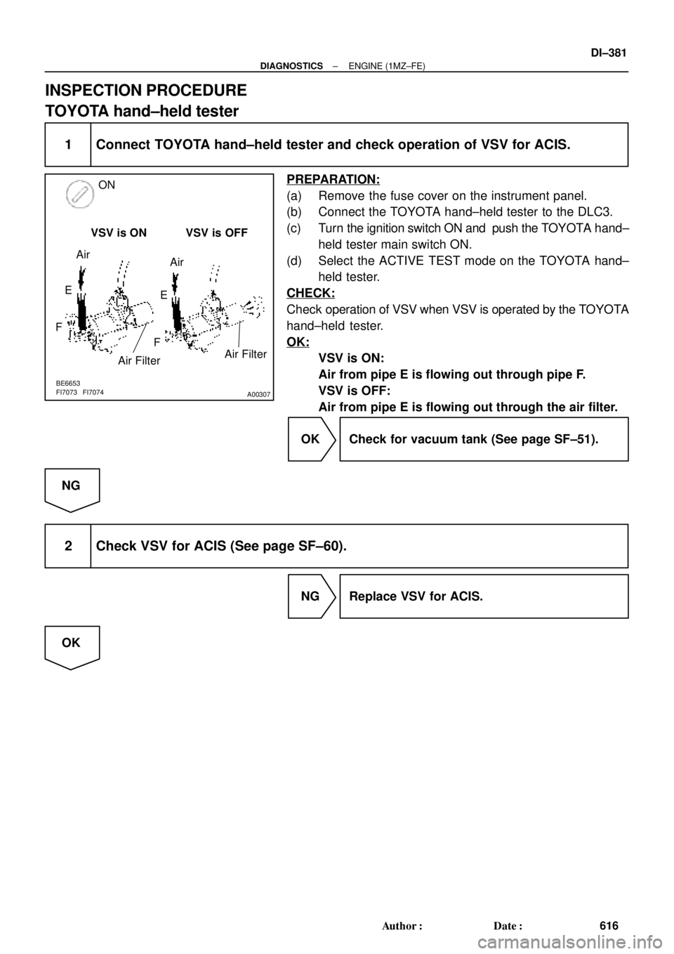
1 Connect TOYOTA hand±held tester and check operation of VSV for ACIS.
PREPARATION:
(a) Remove the fuse cover on the instrument panel.
(b) Connect the TOYOTA hand±held tester to the DLC3.
(c) Turn the ignition switch ON and push the TOYOTA hand±
held tester main switch ON.
(d) Select the ACTIVE TEST mode on the TOYOTA hand±
held tester.
CHECK:
Check operation of VSV when VSV is operated by the TOYOTA
hand±held tester.
OK:
VSV is ON:
Air from pipe E is flowing out through pipe F.
VSV is OFF:
Air from pipe E is flowing out through the air filter.
OK Check for vacuum tank (See page SF±51).
NG
2 Check VSV for ACIS (See page SF±60).
NG Replace VSV for ACIS.
OK
Page 2941 of 4770
F00073
ECU±IGECU±IG
Instrument
Panel J/BECU±IG
± DIAGNOSTICSANTI±LOCK BRAKE SYSTEM (DENSO Made)
DI±521
756 Author�: Date�:
INSPECTION PROCEDURE
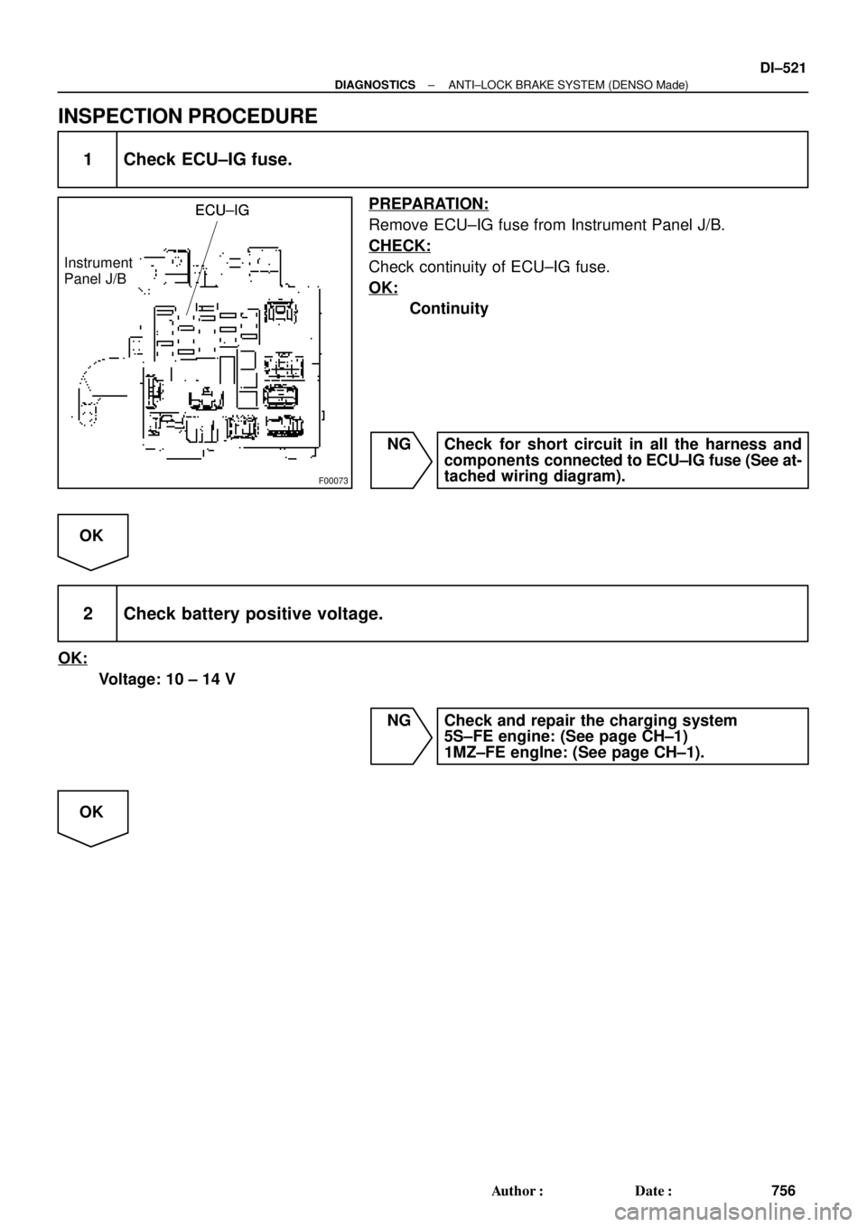
1 Check ECU±IG fuse.
PREPARATION:
Remove ECU±IG fuse from Instrument Panel J/B.
CHECK:
Check continuity of ECU±IG fuse.
OK:
Continuity
NG Check for short circuit in all the harness and
components connected to ECU±IG fuse (See at-
tached wiring diagram).
OK
2 Check battery positive voltage.
OK:
Voltage: 10 ± 14 V
NG Check and repair the charging system
5S±FE engine: (See page CH±1)
1MZ±FE engIne: (See page CH±1).
OK
Page 2942 of 4770
F07151
ON
(+)(±)
IG1GND
GND
F07152F07216
LOCK
(±) GND
GND(+)
DI±522
± DIAGNOSTICSANTI±LOCK BRAKE SYSTEM (DENSO Made)
757 Author�: Date�:
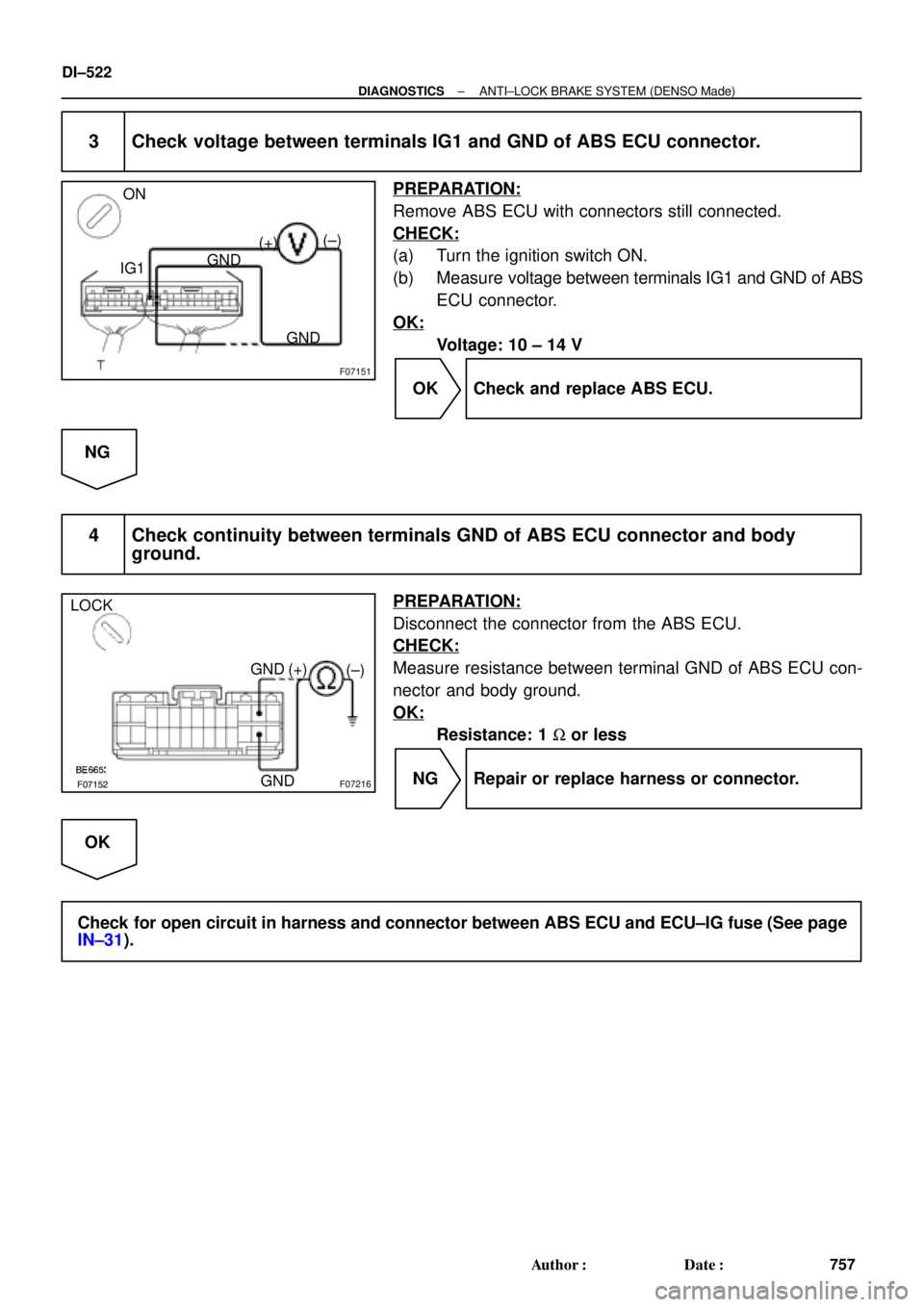
3 Check voltage between terminals IG1 and GND of ABS ECU connector.
PREPARATION:
Remove ABS ECU with connectors still connected.
CHECK:
(a) Turn the ignition switch ON.
(b) Measure voltage between terminals IG1 and GND of ABS
ECU connector.
OK:
Voltage: 10 ± 14 V
OK Check and replace ABS ECU.
NG
4 Check continuity between terminals GND of ABS ECU connector and body
ground.
PREPARATION:
Disconnect the connector from the ABS ECU.
CHECK:
Measure resistance between terminal GND of ABS ECU con-
nector and body ground.
OK:
Resistance: 1 W or less
NG Repair or replace harness or connector.
OK
Check for open circuit in harness and connector between ABS ECU and ECU±IG fuse (See page
IN±31).
Page 2947 of 4770
± DIAGNOSTICSANTI±LOCK BRAKE SYSTEM (DENSO Made)
DI±527
762 Author�: Date�:
DTC Always ON ABS ECU Malfunction
CIRCUIT DESCRIPTION
DTC No.DTC Detecting ConditionTrouble Area
Always ONABS ECU internal malfunction is detected.�ECU
�Battery
Fail safe function:
If trouble occurs in the power source circuit, the ECU cuts off current to the ABS solenoid relay and prohibits
ABS control.
INSPECTION PROCEDURE
1 Is DTC output?
Check DTC on page DI±493.
YES Repair circuit indicated by the code output.
NO
2 Is normal code displayed?
YES Check ABS solenoid relay. Check for short cir-
cuit in harness and connector between ABS so-
lenoid relay and DLC1 (See page IN±31).
NO
3 Is ABS warning light go off?
YES Check for open or short circuit in harness and
connector between ECU±IG fuse and ABS ECU
(See page IN±31).
NO
DI03P±04
Page 2960 of 4770

775 Author�: Date�:
(d) Clear the DTC.
(1) Using SST, connect terminals Tc and E")
BR3890
F02201
DLC1
TsTc E1
BR3904
0.13 sec. 0.12 sec.
ON
OFF DI±540
± DIAGNOSTICSANTI±LOCK BRAKE SYSTEM (BOSCH Made)
775 Author�: Date�:
(d) Clear the DTC.
(1) Using SST, connect terminals Tc and E
1 of DLC2 or
DLC1.
SST 09843 ± 18020
(2) Turn the ignition switch ON.
(3) Clear the DTC stored in ECU by depressing the
brake pedal 8 or more times within 3 seconds.
(4) Check that the warning light shows the normal
code.
(5) Remove the SST from the terminals of DLC2 or
DLC1.
SST 09843 ± 18020
HINT:
Cancellation cannot be done by removing the battery cable or
ECU±B fuse.
2. SPEED SENSOR SIGNAL
(a) Check the speed sensor signal.
(1) When the ignition switch is turned ON, check that
the ABS warning light goes on for 2 seconds.
(2) Turn the ignition switch OFF.
(3) Using SST, connect terminals Ts and E
1 of DLC1.
SST 09843 ± 18020
(4) Start the engine.
(5) Check that the ABS warning light blinks.
HINT:
If the ABS warning light does not blink, inspect the ABS warning
light circuit (See page DI±565).
(6) Drive vehicle straight forward.
HINT:
Drive vehicle at 45 ± 55 km/h (28 ± 34 mph) for several seconds.
If the brake is applied during the check, the check routine must
be started again.
(7) Stop the vehicle.
(8) Turn the ignition switch OFF.
(9) Disconnect the SST from terminals Ts and E
1 and,
connect the SST to terminals Tc and E
1 of DLC1.
SST 09843 ± 18020
(10) Turn the ignition switch ON.
(11) Read the number of blinks of the ABS warning light.
Page 2967 of 4770
F00064
LOCK
191817
16
(+) (±) LOCK
191817
16
(+) (±)
A6 LOCK
191817
16
(+) (±)
± DIAGNOSTICSANTI±LOCK BRAKE SYSTEM (BOSCH Made)
DI±547
782 Author�: Date�:
INSPECTION PROCEDURE
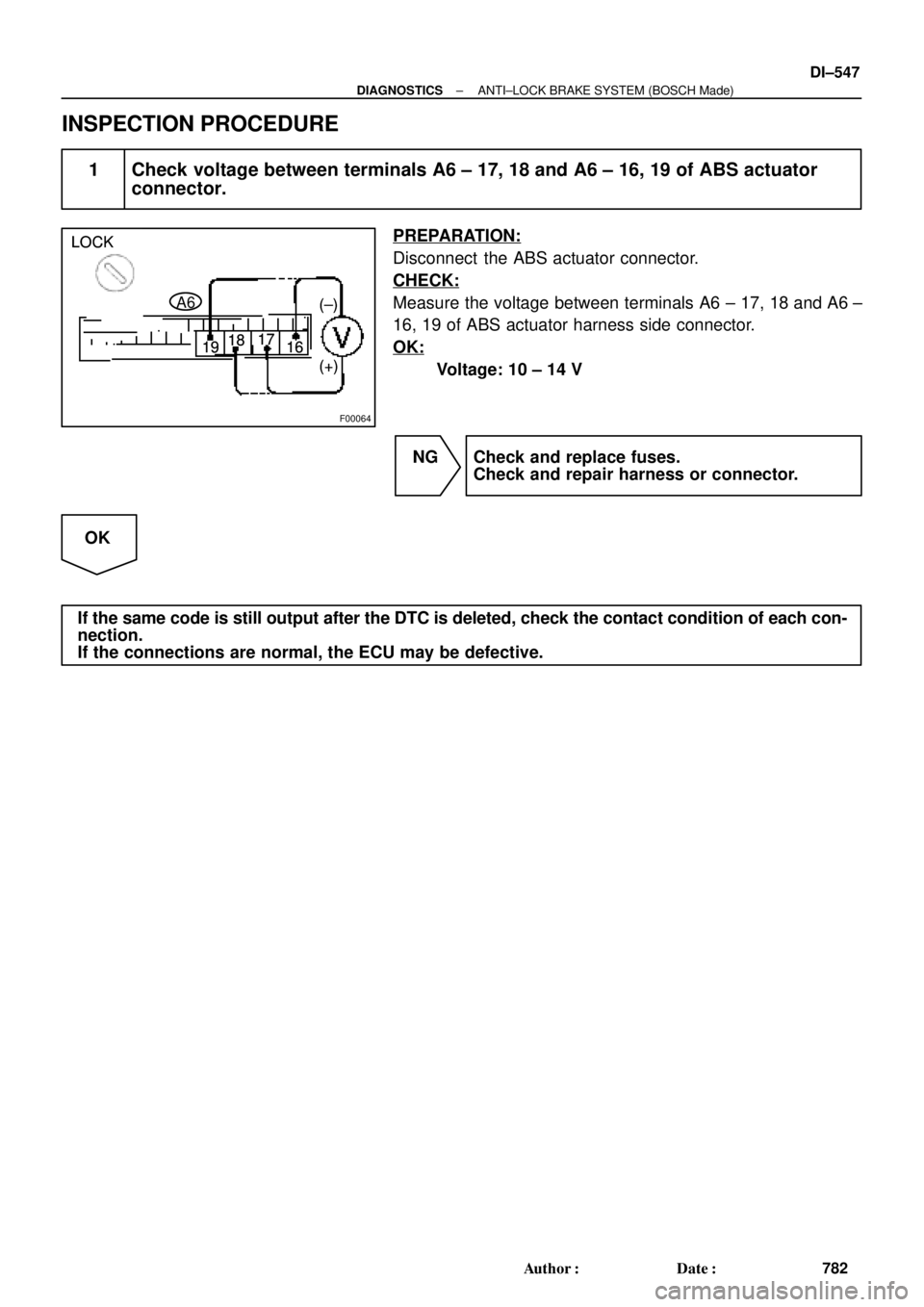
1 Check voltage between terminals A6 ± 17, 18 and A6 ± 16, 19 of ABS actuator
connector.
PREPARATION:
Disconnect the ABS actuator connector.
CHECK:
Measure the voltage between terminals A6 ± 17, 18 and A6 ±
16, 19 of ABS actuator harness side connector.
OK:
Voltage: 10 ± 14 V
NG Check and replace fuses.
Check and repair harness or connector.
OK
If the same code is still output after the DTC is deleted, check the contact condition of each con-
nection.
If the connections are normal, the ECU may be defective.
Page 2969 of 4770
F00064
LOCK
1918 17
16
(+)(±) LOCK
1918 17
16
(+)(±)
A6 LOCK
1918 17
16
(+)(±)
± DIAGNOSTICSANTI±LOCK BRAKE SYSTEM (BOSCH Made)
DI±549
784 Author�: Date�:
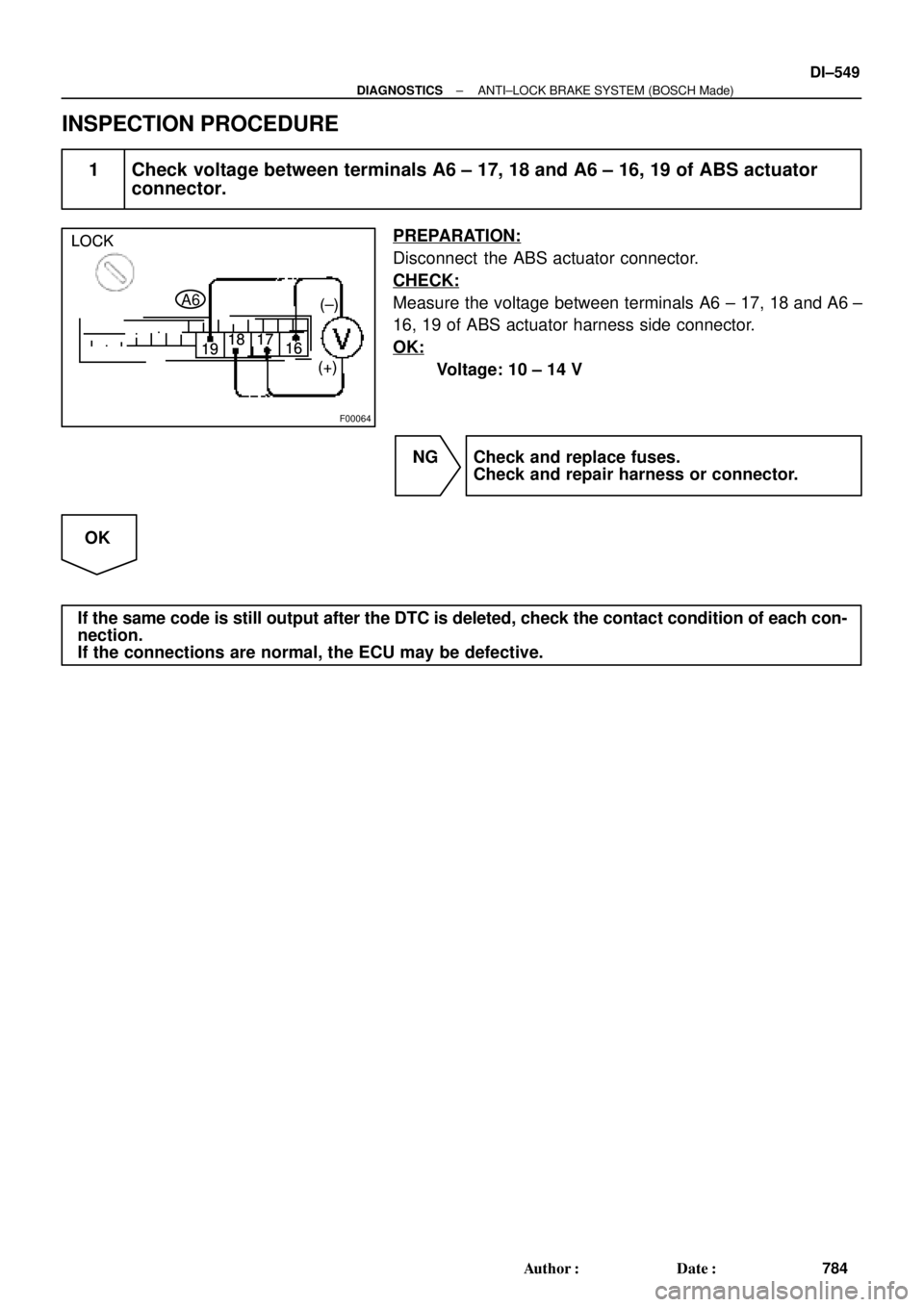
INSPECTION PROCEDURE
1 Check voltage between terminals A6 ± 17, 18 and A6 ± 16, 19 of ABS actuator
connector.
PREPARATION:
Disconnect the ABS actuator connector.
CHECK:
Measure the voltage between terminals A6 ± 17, 18 and A6 ±
16, 19 of ABS actuator harness side connector.
OK:
Voltage: 10 ± 14 V
NG Check and replace fuses.
Check and repair harness or connector.
OK
If the same code is still output after the DTC is deleted, check the contact condition of each con-
nection.
If the connections are normal, the ECU may be defective.