Page 2140 of 4770

BE0AJ±03
Z18937
Connector ºAº Connector ºBº Connector ºCº
Connector ºAº
Connector ºBº
Connector ºCº
J±13±1±A J±16±1 J±13±1
1 2 3 4 5 6 7 8 9 10 11 12 1314 15 16 1 234 56 78 910111213 1 23456 78910111213
C7
C5
A2 B3
A1
C8
B15
C6
B6
A4
C4
B5
C10 B14
A13
B2
C1
B1
C9
A6
A11
A7
A10
A8
A9
C13
B8
B11
B12A5
C11
B4
B16 C2
A12
A3
B7
C3
C12
B9
B10
B13 F
E
T
S
ODOMETER
Fuel Level Warning
Seat Belt Warning
ABS Warning
Low Oil Pressure Warning
Cruise Control Indicator
Malfunction Indicator
O/D OFF Indicator
Light Failure Warning
Brake Warning
SLIP Indicator
TRAC Indicator
Washer Level Warning
Discharge Warning
Right Turn Indicator
Left Turn Indicator
Security Indicator
L
2
D
N
R
P
Illumination
Hi±Beam Indicator
Open Door Warning
SRS Warning
: Fuel Gauge
: Engine Coolant Temperature Gauge
: Tachometer
: Speedometer
No.
A
B
C1
2
3
4
5
6
7 8
9
10
11
12 13
14
15
16
2 3
4
5
6
7 8
9
10
11 12
131
2
3
4 5
6
7
8
9
10
11
12
13
F
E
T
SEngine coolant temperature sender gauge
Ground
Light failure sensor
Integration relay
Traction ECU
Park/neutral position switch (A/T)
O/D OFF switch (A/T)
IGN fuse
Turn signal switch
ST relay
Fuel sender gauge
Generator
Oil pressure switch
Fuel sender gauge
Parking brake switch and brake fluid level warning switch
Headlight dimmer switch
Headlight dimmer switch
Door courtesy switch
DOME fuse
ECU±B fuse
Airbag sensor assembly
ECM
No.1 Vehicle speed sensor Ground
Turn signal switch ECM
Traction ECU
ABS ECU
Ground No.1 Vehicle speed sensor
GAUGE fuse
Igniter
Security ECU
Cruise control ECU
Washer fluid level warning switch
Light control rheostat
TAIL fuse Park/neutral position switch (A/T) Park/neutral position switch (A/T) Park/neutral position switch (A/T) Park/neutral position switch (A/T)
Park/neutral position switch (A/T)Wire Harness Side
Bulb Check
Relay
N20107 N201081
BE±46
± BODY ELECTRICALCOMBINATION METER
2266 Author�: Date�:
CIRCUIT
Page 2145 of 4770

N06640
BE1217
Warning Light
Ignition
Switch
Battery
N02346
OFF
ON
1 2
N01212
BE1217
Warning Light
Ignition
Switch
Battery
± BODY ELECTRICALCOMBINATION METER
BE±51
2271 Author�: Date�:
13. INSPECT LOW OIL PRESSURE SWITCH
(a) Disconnect the connector from the switch.
(b) Check that continuity exists between terminal and ground
with the engine stopped.
(c) Check that no continuity exists between terminal and
ground with the engine running.
HINT:
Oil pressure should be over 24.5 kPa (0.25 kgf/cm
2, 3.55 psi).
If operation is not as specified, replace the switch.
14. INSPECT BRAKE SYSTEM WARNING LIGHT
(a) Disconnect the connector from the brake fluid warning
switch.
(b) Release the parking brake pedal.
(c) Connect the terminals on the wire harness side of the lev-
el warning switch connector.
(d) Start the engine, check that the warning light lights up.
If the warning light does not light up, test the bulb or wire har-
ness.
15. INSPECT BRAKE FLUID LEVEL WARNING SWITCH
(a) Remove the reservoir tank cap and strainer.
(b) Disconnect the connector.
(c) Check that no continuity exists between the terminals with
the switch OFF (float up).
(d) Use syphon, etc. to take fluid out of the reservoir tank.
(e) Check that continuity exists between the terminals with
the switch ON (float down).
(f) Pour the fluid back in the reservoir tank.
If operation is not as specified, replace the switch.
16. INSPECT PARKING BRAKE SWITCH
(a) Check that continuity exists between the terminal and
switch body with the switch ON (switch pin released).
(b) Check that no continuity exists between the terminal and
switch body with the switch OFF (switch pin pushed in).
If operation is not as specified, replace the switch or inspect
ground point.
17. INSPECT WASHER FLUID LEVEL WARNING LIGHT
(a) Disconnect the connectors from the level warning switch
and parking brake switch.
(b) Connect terminals on the wire harness side connector of
the level warning switch connector.
(c) Remove the GAUGE fuse and turn the ignition switch ON,
and check that the warning light comes on.
If the warning light does not light up, test the bulb.
Page 2149 of 4770
BE0AL±03
Z19051
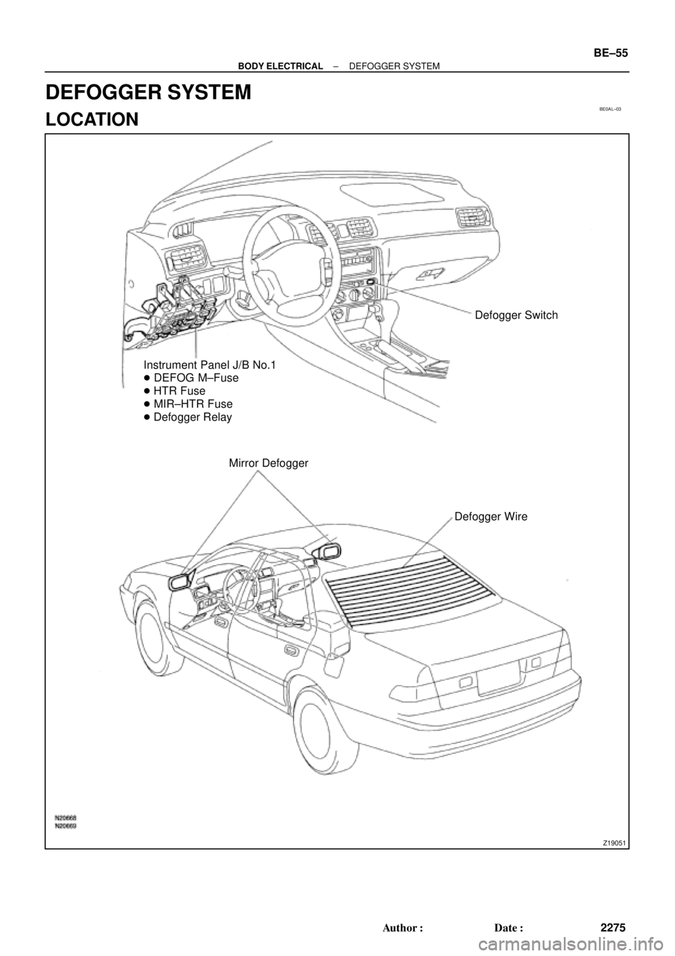
Defogger Switch
Instrument Panel J/B No.1
� DEFOG M±Fuse
� HTR Fuse
� MIR±HTR Fuse
� Defogger Relay
Mirror Defogger
Defogger Wire
± BODY ELECTRICALDEFOGGER SYSTEM
BE±55
2275 Author�: Date�:
DEFOGGER SYSTEM
LOCATION
Page 2153 of 4770
BE0AN±03
Z19052
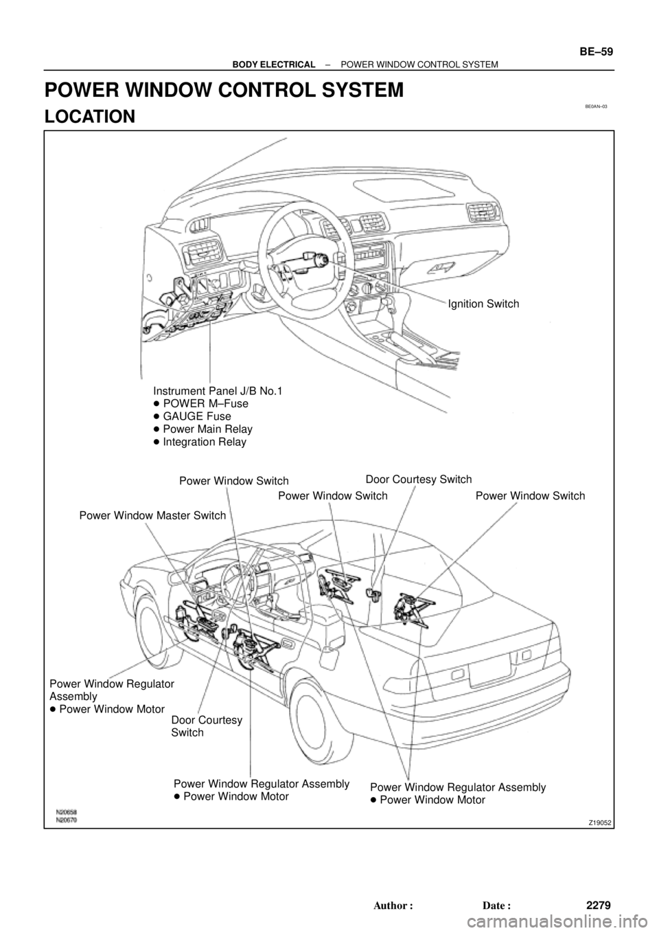
Ignition Switch
Instrument Panel J/B No.1
� POWER M±Fuse
� GAUGE Fuse
� Power Main Relay
� Integration Relay
Power Window Switch
Power Window Master SwitchPower Window SwitchDoor Courtesy Switch
Power Window Switch
Power Window Regulator
Assembly
� Power Window Motor
Door Courtesy
Switch
Power Window Regulator Assembly
� Power Window MotorPower Window Regulator Assembly
� Power Window Motor
± BODY ELECTRICALPOWER WINDOW CONTROL SYSTEM
BE±59
2279 Author�: Date�:
POWER WINDOW CONTROL SYSTEM
LOCATION
Page 2163 of 4770
BE0AP±02
Z19053
Instrument Panel J/B No.1
� POWER M±Fuse
� CIG Fuse
� DOOR Fuse
� Integration Relay
Power Window Master Switch
� Door Lock Control SwitchDoor Key Lock and Unlock Switch
Door Lock Assembly
� Door Lock Motor
� Door Unlock Detection Switch
Door Lock Assembly
� Door Lock Motor
� Door Unlock Detection Switch
Door Lock Control Switch
± BODY ELECTRICALPOWER DOOR LOCK CONTROL SYSTEM
BE±69
2289 Author�: Date�:
POWER DOOR LOCK CONTROL SYSTEM
LOCATION
Page 2167 of 4770
BE0AR±02
Z19490
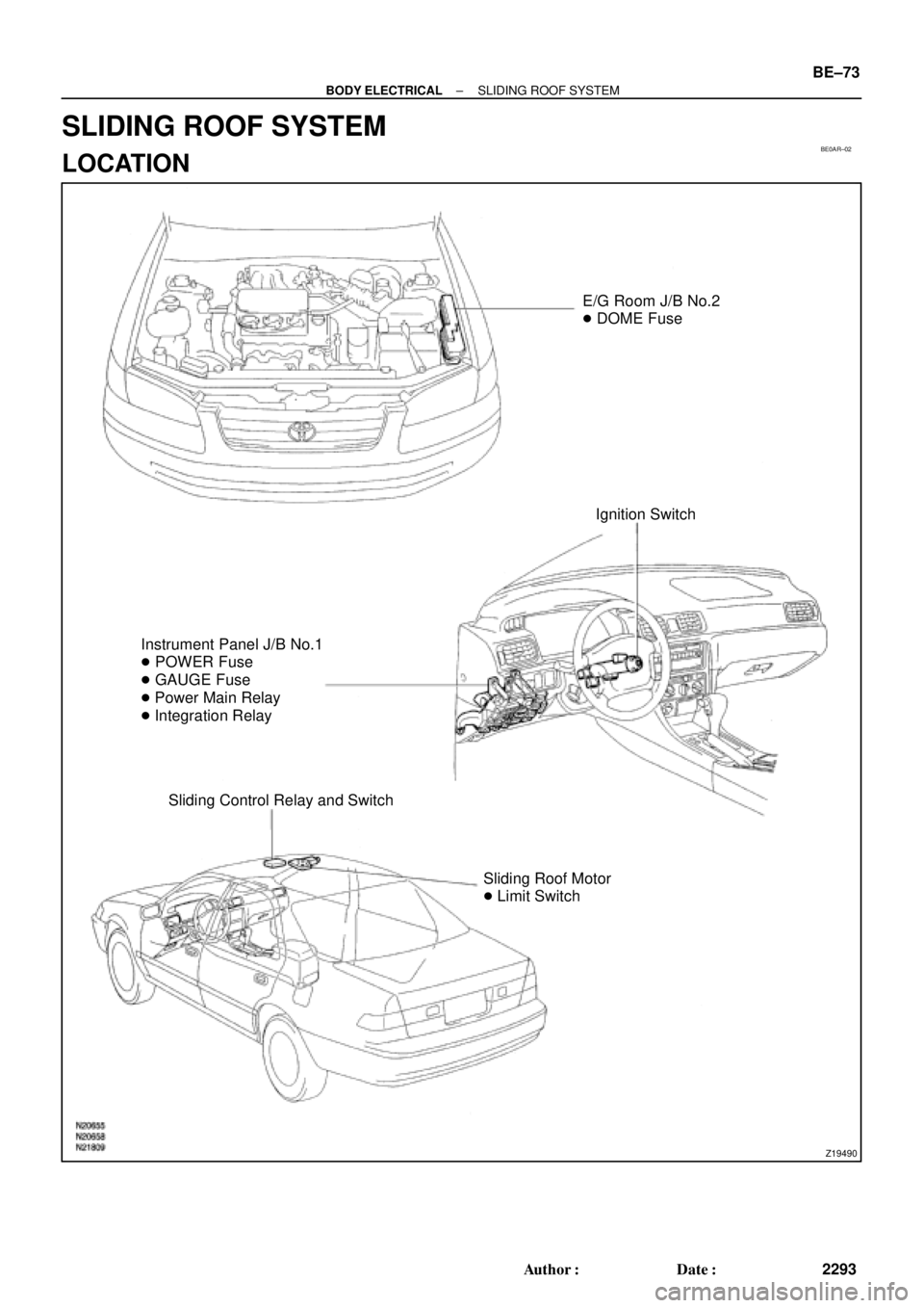
E/G Room J/B No.2
� DOME Fuse
Ignition Switch
Instrument Panel J/B No.1
� POWER Fuse
� GAUGE Fuse
� Power Main Relay
� Integration Relay
Sliding Control Relay and Switch
Sliding Roof Motor
� Limit Switch
± BODY ELECTRICALSLIDING ROOF SYSTEM
BE±73
2293 Author�: Date�:
SLIDING ROOF SYSTEM
LOCATION
Page 2171 of 4770
BE0AT±02
Z19504
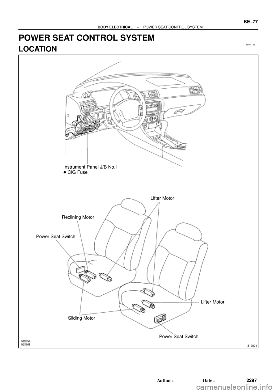
Instrument Panel J/B No.1
� CIG Fuse
Lifter Motor
Power Seat SwitchReclining Motor
Lifter Motor
Sliding Motor
Power Seat Switch
± BODY ELECTRICALPOWER SEAT CONTROL SYSTEM
BE±77
2297 Author�: Date�:
POWER SEAT CONTROL SYSTEM
LOCATION
Page 2176 of 4770
BE0AV±03
Z19488
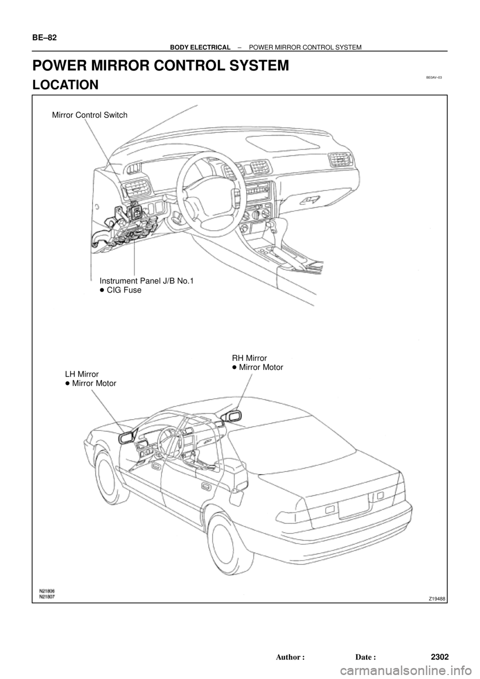
Mirror Control Switch
Instrument Panel J/B No.1
� CIG Fuse
LH Mirror
� Mirror MotorRH Mirror
� Mirror Motor BE±82
± BODY ELECTRICALPOWER MIRROR CONTROL SYSTEM
2302 Author�: Date�:
POWER MIRROR CONTROL SYSTEM
LOCATION