Page 1507 of 4770

K POWER SOURCE (Current Flow Chart)
FuseSystemPage
15ASTOP
ABS (TMC Made)
ABS (TMMK Made)
ABS and Traction Control
Cruise Control
Electronically Controlled Transmission and A/T Indicator (1MZ±FE)
Electronically Controlled Transmission and A/T Indicator (5S±FE)
Engine Control (1MZ±FE)
Engine Control (5S±FE)
Shift Lock
Stop Light234
240
226
218
202
210
66
82
252
11 8
25AWIPERWiper and Washer140
25ADOOR
Door Lock Control (TMC Made)
Door Lock Control (TMMK Made)
Moon Roof
Power Window
Theft Deterrent (TMC Made)
Theft Deterrent (TMMK Made)
Wireless Door Lock Control (TMC Made)
Wireless Door Lock Control (TMMK Made)150
156
194
144
182
188
162
172
30APOWER
Door Lock Control (TMC Made)
Door Lock Control (TMMK Made)
Moon Roof
Power Seat
Power Window150
156
194
198
144
40AAM1Charging
Radiator Fan and Condenser Fan62
288
40ADEFRear Window Defogger and Mirror Heater268
Engine Room J/B No.2 (See Page 22)
FuseSystemPage
5AALT±SCharging62
7.5ADOME
Cigarette Lighter and Clock
Combination Meter
Headlight (w/ Daytime Running Light)
Interior Light
Key Reminder and Seat Belt Warning
Light Auto Turn Off
Moon Roof
Theft Deterrent (TMC Made)
Theft Deterrent (TMMK Made)
Wireless Door Lock Control (TMC Made)
Wireless Door Lock Control (TMMK Made)258
280
100
122
260
11 0
194
182
188
162
172
*These are the page numbers of the first page on which the related system is shown.
Page 1508 of 4770

K
FuseSystemPage
10AECU±B
Air Conditioning (Automatic A/C)
Combination Meter
SRS292
280
245
10AHAZARDTurn Signal and Hazard Warning Light11 4
10AHORN
Horn
Theft Deterrent (TMC Made)
Theft Deterrent (TMMK Made)
Wireless Door Lock Control (TMC Made)
Wireless Door Lock Control (TMMK Made)256
182
188
162
172
15AEFI
Electronically Controlled Transmission and A/T Indicator (1MZ±FE)
Electronically Controlled Transmission and A/T Indicator (5S±FE)
Engine Control (1MZ±FE)
Engine Control (5S±FE)
Engine Immobiliser System202
210
66
82
94
15AHEAD (LH)Headlight (w/o Daytime Running Light)96
15AHEAD (RH)Headlight (w/o Daytime Running Light)96
15AHEAD LH (UPR)Headlight (w/ Daytime Running Light)100
15AHEAD RH (UPR)Headlight (w/ Daytime Running Light)100
20ARADIO NO.1
Auto Antenna
Radio and Player (Built±In Type Amplifier)
Radio and Player (Separate Type Amplifier)272
278
274
30AAM2
Charging
Engine Control (1MZ±FE)
Engine Control (5S±FE)
Starting and Ignition (1MZ±FE)
Starting and Ignition (5S±FE)62
66
82
54
58
30ACDSRadiator Fan and Condenser Fan288
30ARDIRadiator Fan and Condenser Fan288
40AMAIN
Headlight (w/ Daytime Running Light)
Headlight (w/o Daytime Running Light)
Light Auto Turn Off
Starting and Ignition (1MZ±FE)
Starting and Ignition (5S±FE)
Theft Deterrent (TMC Made)
Theft Deterrent (TMMK Made)
Wireless Door Lock Control (TMC Made)
Wireless Door Lock Control (TMMK Made)100
96
11 0
54
58
182
188
162
172
Engine Room R/B No.1 (See Page 24)
FuseSystemPage
10AA/CAir Conditioning (Manual A/C)300
25AA/F HTREngine Control (1MZ±FE)66
*These are the page numbers of the first page on which the related system is shown.
Page 1509 of 4770
K POWER SOURCE (Current Flow Chart)
Engine Room R/B No.2 (See Page 24)
FuseSystemPage
5ADRL NO.2Headlight (w/ Daytime Running Light)100
10AH±LP LH (LWR)Headlight (w/ Daytime Running Light)100
10AH±LP RH (LWR)Headlight (w/ Daytime Running Light)100
Engine Room R/B No.3 (TMMK Made w/ ABS and Traction Control)
(TMC Made w/ ABS, w/ ABS and Traction Control)
or
Fusible Link Block
(TMMK Made w/ ABS w/o Traction Control) (See Page 25)
FuseSystemPage
60AFL ABS
ABS (TMC Made)
ABS (TMMK Made)
ABS and Traction Control234
240
226
*These are the page numbers of the first page on which the related system is shown.
Page 1536 of 4770

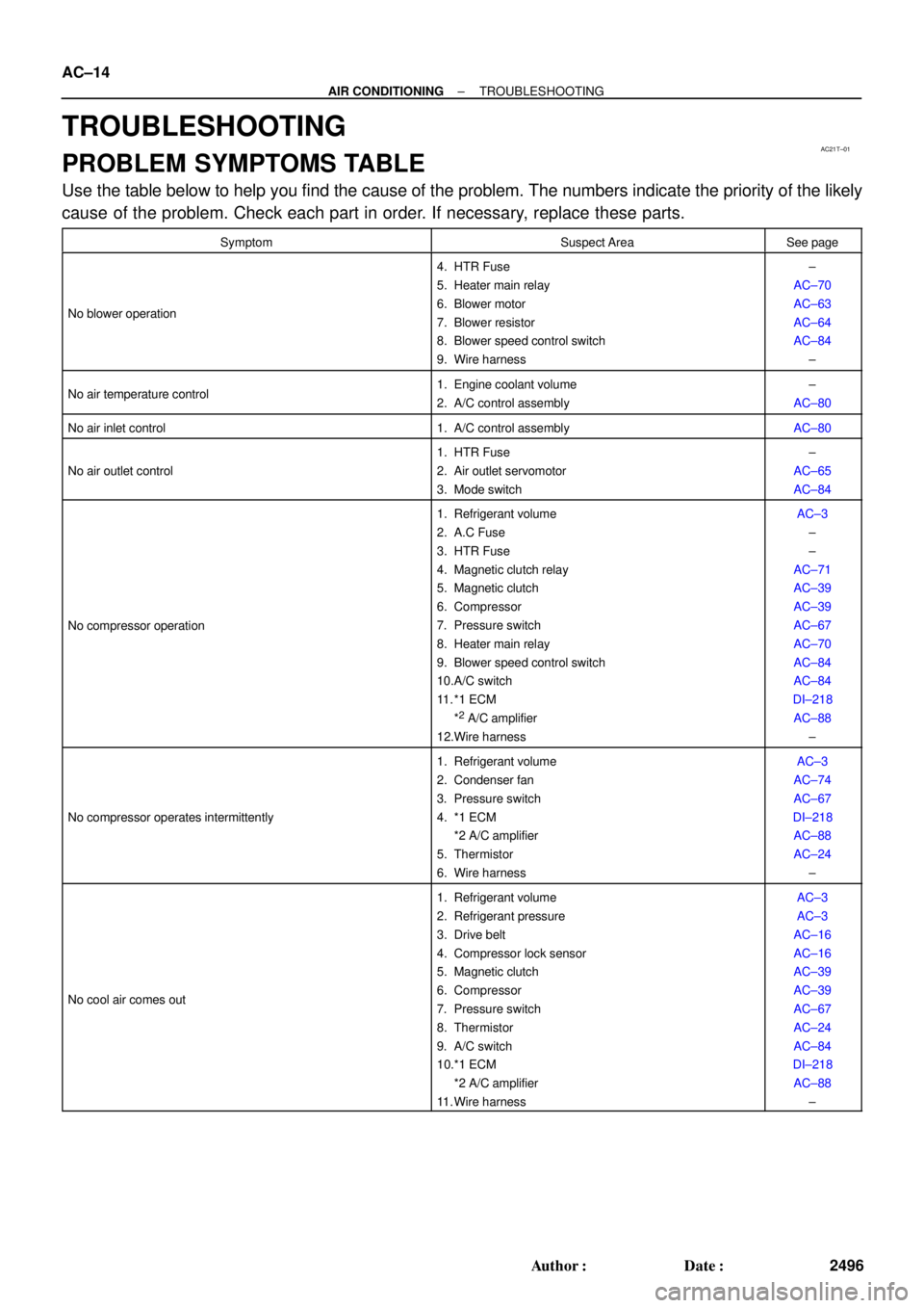
AC21T±01
AC±14
± AIR CONDITIONINGTROUBLESHOOTING
2496 Author�: Date�:
TROUBLESHOOTING
PROBLEM SYMPTOMS TABLE
Use the table below to help you find the cause of the problem. The numbers indicate the priority of the likely
cause of the problem. Check each part in order. If necessary, replace these parts.
SymptomSuspect AreaSee page
No blower operation
4. HTR Fuse
5. Heater main relay
6. Blower motor
7. Blower resistor
8. Blower speed control switch
9. Wire harness±
AC±70
AC±63
AC±64
AC±84
±
No air temperature control1. Engine coolant volume
2. A/C control assembly±
AC±80
No air inlet control1. A/C control assemblyAC±80
No air outlet control
1. HTR Fuse
2. Air outlet servomotor
3. Mode switch±
AC±65
AC±84
No compressor operation
1. Refrigerant volume
2. A.C Fuse
3. HTR Fuse
4. Magnetic clutch relay
5. Magnetic clutch
6. Compressor
7. Pressure switch
8. Heater main relay
9. Blower speed control switch
10.A/C switch
11. *1 ECM
*
2 A/C amplifier
12.Wire harness
AC±3
±
±
AC±71
AC±39
AC±39
AC±67
AC±70
AC±84
AC±84
DI±218
AC±88
±
No compressor operates intermittently
1. Refrigerant volume
2. Condenser fan
3. Pressure switch
4. *1 ECM
*2 A/C amplifier
5. Thermistor
6. Wire harnessAC±3
AC±74
AC±67
DI±218
AC±88
AC±24
±
No cool air comes out
1. Refrigerant volume
2. Refrigerant pressure
3. Drive belt
4. Compressor lock sensor
5. Magnetic clutch
6. Compressor
7. Pressure switch
8. Thermistor
9. A/C switch
10.*1 ECM
*2 A/C amplifier
11. Wire harnessAC±3
AC±3
AC±16
AC±16
AC±39
AC±39
AC±67
AC±24
AC±84
DI±218
AC±88
±
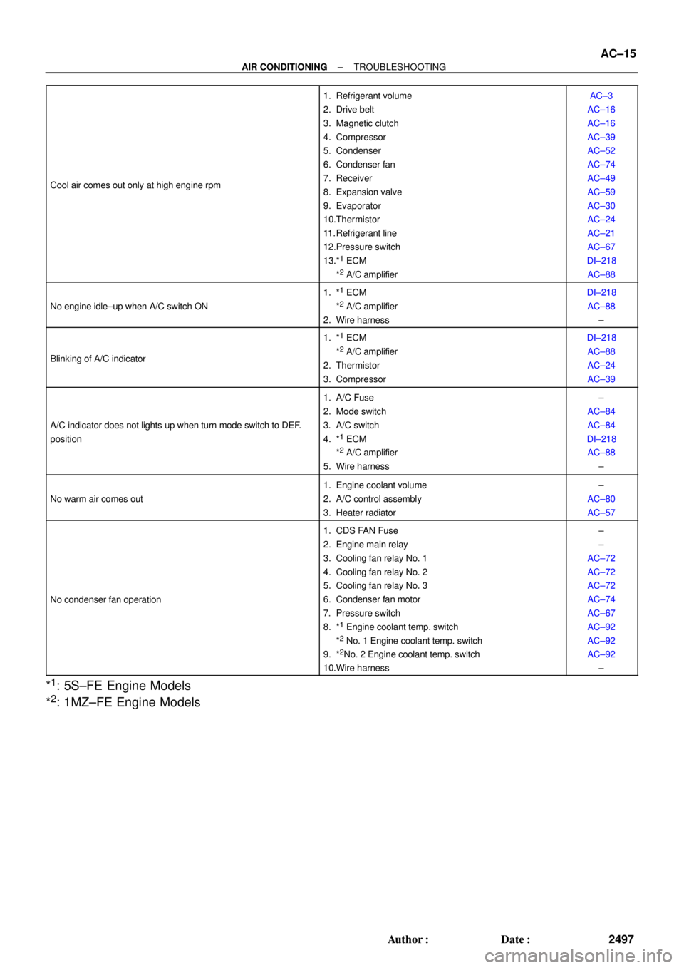
Page 1537 of 4770

± AIR CONDITIONINGTROUBLESHOOTING
AC±15
2497 Author�: Date�:
Cool air comes out only at high engine rpm
1. Refrigerant volume
2. Drive belt
3. Magnetic clutch
4. Compressor
5. Condenser
6. Condenser fan
7. Receiver
8. Expansion valve
9. Evaporator
10.Thermistor
11. Refrigerant line
12.Pressure switch
13.*
1 ECM
*2 A/C amplifier
AC±3
AC±16
AC±16
AC±39
AC±52
AC±74
AC±49
AC±59
AC±30
AC±24
AC±21
AC±67
DI±218
AC±88
No engine idle±up when A/C switch ON
1. *1 ECM
*2 A/C amplifier
2. Wire harness
DI±218
AC±88
±
Blinking of A/C indicator
1. *1 ECM
*2 A/C amplifier
2. Thermistor
3. Compressor
DI±218
AC±88
AC±24
AC±39
A/C indicator does not lights up when turn mode switch to DEF.
position
1. A/C Fuse
2. Mode switch
3. A/C switch
4. *
1 ECM
*2 A/C amplifier
5. Wire harness
±
AC±84
AC±84
DI±218
AC±88
±
No warm air comes out
1. Engine coolant volume
2. A/C control assembly
3. Heater radiator±
AC±80
AC±57
No condenser fan operation
1. CDS FAN Fuse
2. Engine main relay
3. Cooling fan relay No. 1
4. Cooling fan relay No. 2
5. Cooling fan relay No. 3
6. Condenser fan motor
7. Pressure switch
8. *
1 Engine coolant temp. switch
*2 No. 1 Engine coolant temp. switch
9. *2No. 2 Engine coolant temp. switch
10.Wire harness
±
±
AC±72
AC±72
AC±72
AC±74
AC±67
AC±92
AC±92
AC±92
±
*1: 5S±FE Engine Models
*
2: 1MZ±FE Engine Models
Page 1620 of 4770

INTRODUCTIONGENERAL REPAIR INSTRUCTIONS ±
IN±5
the specified seal lock adhesive to the bolt, nut or
threads.
(c) Precoated parts are indicated in the component il-
lustrations by the º�º symbol.
7. When necessary, use a sealer on gaskets to prevent
leaks.
8. Carefully observe all specifications for bolt tightening
torques. Always use a torque wrench.
9. Use of special service tools (SST) and special service ma-
terials (SSM) may be required, depending on the nature
of the repair. Be sure to use SST and SSM where speci-
fied and follow the proper work procedure. A list of SST
and SSM can be found at the preparation of AX section.
10. When replacing fuses, be sure the new fuse has the cor-
rect amperage rating. DO NOT exceed the rating or use
one with a lower rating.
11. To pull apart electrical connectors, pull on the connector
itself, not the wires.
12. Care must be taken when jacking up and supporting the
vehicle. Be sure to lift and support the vehicle at the prop-
er locations.
(a) If the vehicle is to be jacked up only at the front or
rear end, be sure to block the wheels at the opposite
end in order to ensure safety.
(b) After the vehicle is jacked up, be sure to support it on
stands. It is extremely dangerous to do any work on
a vehicle raised on a jack alone, even for a small job
that can be finished quickly.
Page 1790 of 4770

INTRODUCTIONGENERAL REPAIR INSTRUCTIONS ±
IN±5
the specified seal lock adhesive to the bolt, nut or
threads.
(c) Precoated parts are indicated in the component il-
lustrations by the º�º symbol.
7. When necessary, use a sealer on gaskets to prevent
leaks.
8. Carefully observe all specifications for bolt tightening
torques. Always use a torque wrench.
9. Use of special service tools (SST) and special service ma-
terials (SSM) may be required, depending on the nature
of the repair. Be sure to use SST and SSM where speci-
fied and follow the proper work procedure. A list of SST
and SSM can be found at the preparation of AX section.
10. When replacing fuses, be sure the new fuse has the cor-
rect amperage rating. DO NOT exceed the rating or use
one with a lower rating.
11. To pull apart electrical connectors, pull on the connector
itself, not the wires.
12. Care must be taken when jacking up and supporting the
vehicle. Be sure to lift and support the vehicle at the prop-
er locations.
(a) If the vehicle is to be jacked up only at the front or
rear end, be sure to block the wheels at the opposite
end in order to ensure safety.
(b) After the vehicle is jacked up, be sure to support it on
stands. It is extremely dangerous to do any work on
a vehicle raised on a jack alone, even for a small job
that can be finished quickly.
Page 2096 of 4770

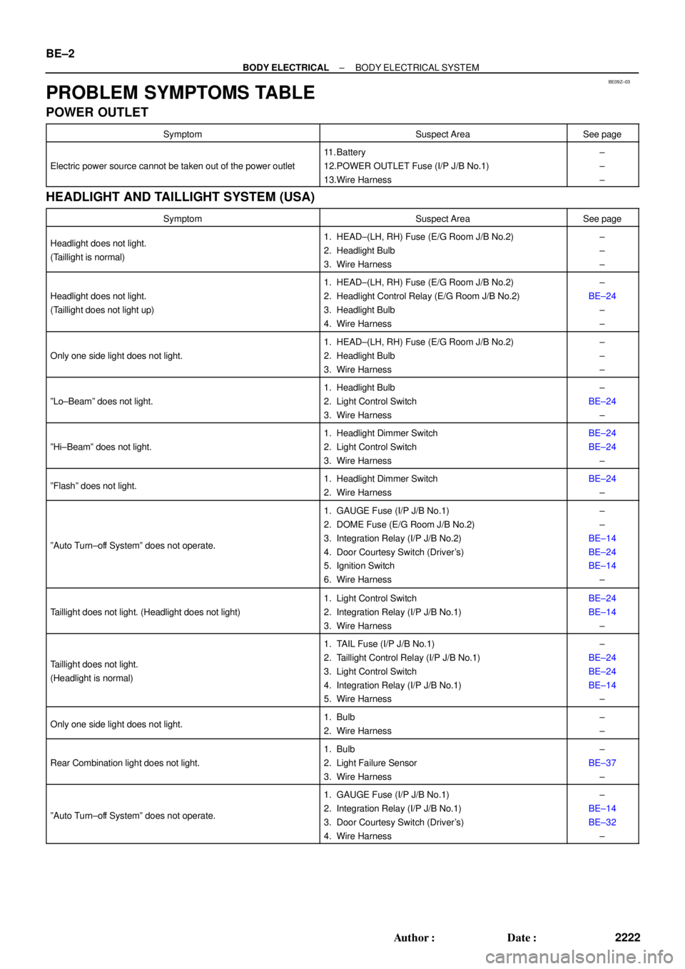
BE09Z±03
BE±2
± BODY ELECTRICALBODY ELECTRICAL SYSTEM
2222 Author�: Date�:
PROBLEM SYMPTOMS TABLE
POWER OUTLET
SymptomSuspect AreaSee page
Electric power source cannot be taken out of the power outlet
11. Battery
12.POWER OUTLET Fuse (I/P J/B No.1)
13.Wire Harness±
±
±
HEADLIGHT AND TAILLIGHT SYSTEM (USA)
SymptomSuspect AreaSee page
Headlight does not light.
(Taillight is normal)1. HEAD±(LH, RH) Fuse (E/G Room J/B No.2)
2. Headlight Bulb
3. Wire Harness±
±
±
Headlight does not light.
(Taillight does not light up)
1. HEAD±(LH, RH) Fuse (E/G Room J/B No.2)
2. Headlight Control Relay (E/G Room J/B No.2)
3. Headlight Bulb
4. Wire Harness±
BE±24
±
±
Only one side light does not light.
1. HEAD±(LH, RH) Fuse (E/G Room J/B No.2)
2. Headlight Bulb
3. Wire Harness±
±
±
ºLo±Beamº does not light.
1. Headlight Bulb
2. Light Control Switch
3. Wire Harness±
BE±24
±
ºHi±Beamº does not light.
1. Headlight Dimmer Switch
2. Light Control Switch
3. Wire HarnessBE±24
BE±24
±
ºFlashº does not light.1. Headlight Dimmer Switch
2. Wire HarnessBE±24
±
ºAuto Turn±off Systemº does not operate.
1. GAUGE Fuse (I/P J/B No.1)
2. DOME Fuse (E/G Room J/B No.2)
3. Integration Relay (I/P J/B No.2)
4. Door Courtesy Switch (Driver's)
5. Ignition Switch
6. Wire Harness±
±
BE±14
BE±24
BE±14
±
Taillight does not light. (Headlight does not light)
1. Light Control Switch
2. Integration Relay (I/P J/B No.1)
3. Wire HarnessBE±24
BE±14
±
Taillight does not light.
(Headlight is normal)
1. TAIL Fuse (I/P J/B No.1)
2. Taillight Control Relay (I/P J/B No.1)
3. Light Control Switch
4. Integration Relay (I/P J/B No.1)
5. Wire Harness±
BE±24
BE±24
BE±14
±
Only one side light does not light.1. Bulb
2. Wire Harness±
±
Rear Combination light does not light.
1. Bulb
2. Light Failure Sensor
3. Wire Harness±
BE±37
±
ºAuto Turn±off Systemº does not operate.
1. GAUGE Fuse (I/P J/B No.1)
2. Integration Relay (I/P J/B No.1)
3. Door Courtesy Switch (Driver's)
4. Wire Harness±
BE±14
BE±32
±