2000 TOYOTA CAMRY Fuse a
[x] Cancel search: Fuse aPage 1165 of 4770
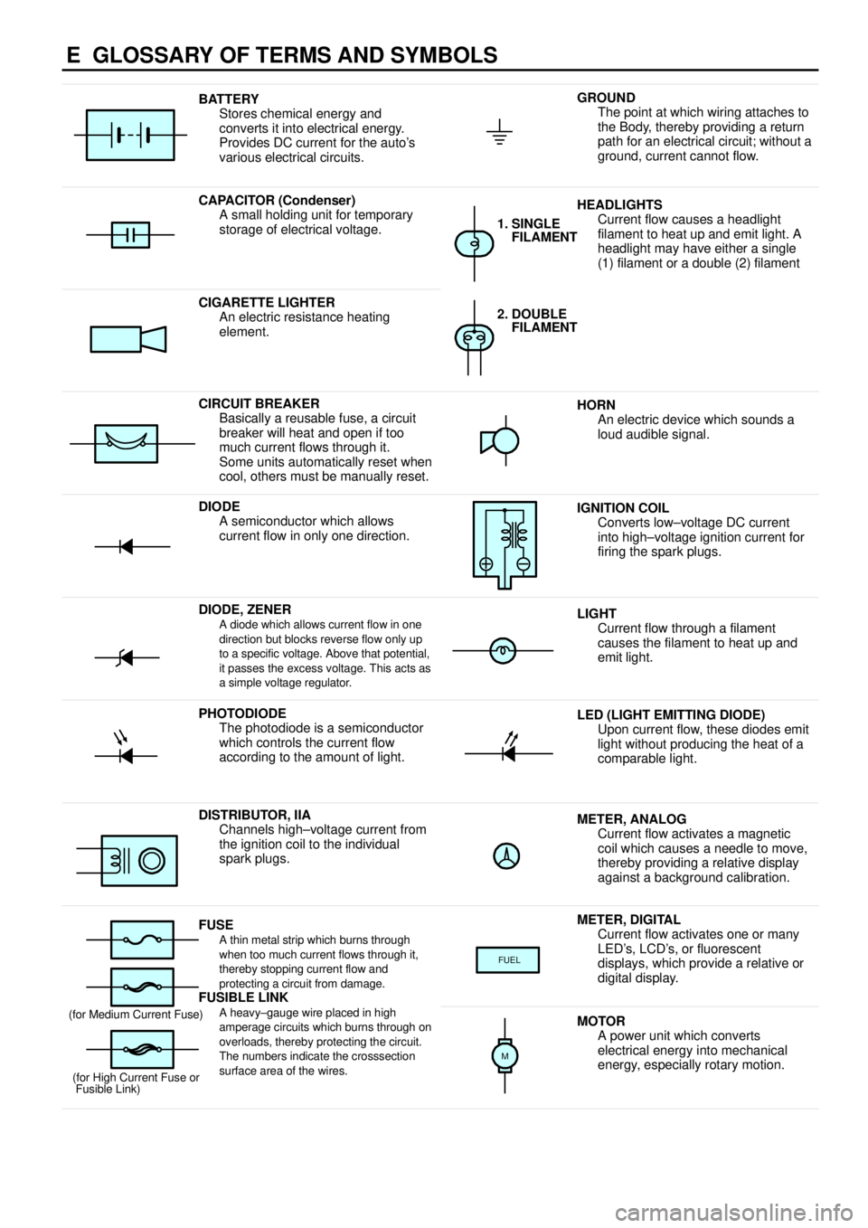
E GLOSSARY OF TERMS AND SYMBOLS
BATTERY
Stores chemical energy and
converts it into electrical energy.
Provides DC current for the auto's
various electrical circuits.GROUND
The point at which wiring attaches to
the Body, thereby providing a return
path for an electrical circuit; without a
ground, current cannot flow.
CAPACITOR (Condenser)
A small holding unit for temporary
storage of electrical voltage.HEADLIGHTS
Current flow causes a headlight
filament to heat up and emit light. A
headlight may have either a single
(1) filament or a double (2) filament
1. SINGLE
FILAMENT
CIGARETTE LIGHTER
An electric resistance heating
element.2. DOUBLE
FILAMENT
CIRCUIT BREAKER
Basically a reusable fuse, a circuit
breaker will heat and open if too
much current flows through it.
Some units automatically reset when
cool, others must be manually reset.HORN
An electric device which sounds a
loud audible signal.
DIODE
A semiconductor which allows
current flow in only one direction.IGNITION COIL
Converts low±voltage DC current
into high±voltage ignition current for
firing the spark plugs.
DIODE, ZENERA diode which allows current flow in one
direction but blocks reverse flow only up
to a specific voltage. Above that potential,
it passes the excess voltage. This acts as
a simple voltage regulator.LIGHT
Current flow through a filament
causes the filament to heat up and
emit light.
PHOTODIODE
The photodiode is a semiconductor
which controls the current flow
according to the amount of light.LED (LIGHT EMITTING DIODE)
Upon current flow, these diodes emit
light without producing the heat of a
comparable light.
DISTRIBUTOR, IIA
Channels high±voltage current from
the ignition coil to the individual
spark plugs.METER, ANALOG
Current flow activates a magnetic
coil which causes a needle to move,
thereby providing a relative display
against a background calibration.
FUSEA thin metal strip which burns through
when too much current flows through it,
thereby stopping current flow and
protecting a circuit from damage.
FUSIBLE LINK
METER, DIGITAL
Current flow activates one or many
LED's, LCD's, or fluorescent
displays, which provide a relative or
digital display.
FUEL
FUSIBLE LINK
A heavy±gauge wire placed in high
amperage circuits which burns through on
overloads, thereby protecting the circuit.
The numbers indicate the crosssection
surface area of the wires.(for Medium Current Fuse)
(for High Current Fuse or
Fusible Link)MOTOR
A power unit which converts
electrical energy into mechanical
energy, especially rotary motion.
M
Page 1251 of 4770

HEADLIGHT (w/ DAYTIME RUNNING LIGHT)
The current from the FL MAIN is always flowing from the MAIN fuse to HEAD relay (Coil side) to TERMINAL H±LP of the
daytime running light relay (Main), from DOME fuse to TERMINAL +B of the daytime running light relay (Main) and from the
ALT fuse to Taillight relay (Coil side) to TERMINAL TAIL (TMMK Made) of the daytime running light relay (Main).
When the ignition SW is turned on, the current flowing through the GAUGE fuse flows to TERMINAL IG of the daytime
running light relay (Main).
1. DAYTIME RUNNING LIGHT OPERATION
When the engine is started, voltage generated at TERMINAL L of the generator is applied to TERMINAL CHG± of the
daytime running light relay (Main). If the parking brake lever is pulled up (Parking brake SW on) at this time, the relay is not
activated so the daytime running light system does not operate. If the parking brake lever is then released (Parking brake
SW off), a signal is input to TERMINAL PKB of the relay.
This activates the daytime running light relay (Main) and the HEAD relay is turned to on, so the current flows from the MAIN
fuse to the HEAD relay (Point side) to TERMINAL 1 of the DIM relay to TERMINAL 4 to H±LP LH (LWR), H±LP RH (LWR)
fuses to TERMINAL 1 of the headlights to TERMINAL 3 to TERMINAL 1 of the daytime running light resistor to TERMINAL 2
to GROUND, causing the headlights to light up (Headlights light up dimmer than normal brightness.). Once the daytime
running light system operates and the headlights light up, the headlights remain on even if the parking brake lever is pulled
up (Parking brake SW on).
If the engine stalls and the ignition SW remains on, the headlights remain light up even through current is no longer output
from TERMINAL L of the generator. If the ignition SW is then turned off, the headlights go off.
If the engine is started with the parking brake lever released (Parking brake SW off), the daytime running light system
operates and headlights light up when the engine starts.
2. HEADLIGHT OPERATION
When the light control SW is switched to HEAD position and the dimmer SW is set to LOW position, causing the daytime
running light relay (Main) and the HEAD relay to turn on, so the current flows from the MAIN fuse to HEAD relay (Point side)
to DRL NO.2 fuse to TERMINAL 3 of the DRL NO.4 relay to TERMINAL 4 to TERMINAL H±ON of the daytime running light
relay (Main) to TERMINAL H to TERMINAL 3 of the integration relay to TERMINAL 4 to TERMINAL 13 of the light control
SW to TERMINAL 16 to GROUND, activating the DRL. NO.4 relay. The current to HEAD relay (Point side) then flows to
TERMINAL 1 of the DIM relay to TERMINAL 4 to H±LP LH (LWR), H±LP RH (LWR) fuses to TERMINAL 1 of the headlights
to TERMINAL 3 to TERMINAL 1 of the DRL NO.4 relay to TERMINAL 2 to GROUND, causing the headlights to light up at
normal intensity.
When the light control SW is switched to HEAD position and the dimmer SW is set to HIGH position, the signal from the
dimmer SW is input to the daytime running light relay (Main). This activates the daytime running light relay (Main) and the
HEAD relay is turned on, so the current flows from the MAIN fuse to HEAD relay (Point side) to TERMINAL 1 of the DIM
relay to TERMINAL 3 to TERMINAL DIM of the daytime running light relay (Main), activating the DIM relay. This causes
current to flow from TERMINAL 1 of the DIM relay to TERMINAL 2 to HEAD LH (UPR), HEAD RH (UPR) fuses to TERMINAL
2 of the headlights to TERMINAL 3 to TERMINAL 1 of the DRL NO.4 relay to TERMINAL 2 to GROUND, causing the
headlights to light up at high beam and the high beam indicator light to light up.
When the dimmer SW is switched to FLASH position, the signal from the dimmer SW is input to the daytime running light
relay (Main). This activates the daytime running light relay (Main) and the HEAD relay is turned on, so the current flows from
the MAIN fuse to HEAD relay (Point side) to DRL NO.2 fuse to TERMINAL 3 of the DRL NO.4 relay to TERMINAL 4 to
TERMINAL H±ON of the daytime running light relay (Main) to TERMINAL H to TERMINAL 8 of the dimmer SW to
TERMINAL 16 to GROUND, activating the DRL NO.4 relay. At the same time, the current flows from the TERMINAL 1 of the
DIM relay to TERMINAL 3 to TERMINAL DIM of the daytime running light relay (Main), activating the DIM relay, and also
flows from the HEAD LH (UPR), HEAD RH (UPR) fuses to TERMINAL 2 of the headlights to TERMINAL 3 to TERMINAL 1 of
the DRL NO.4 relay to TERMINAL 2 to GROUND, causing the headlights to light up at high beam and the high beam
indicator light to light up.
SYSTEM OUTLINE
Page 1252 of 4770
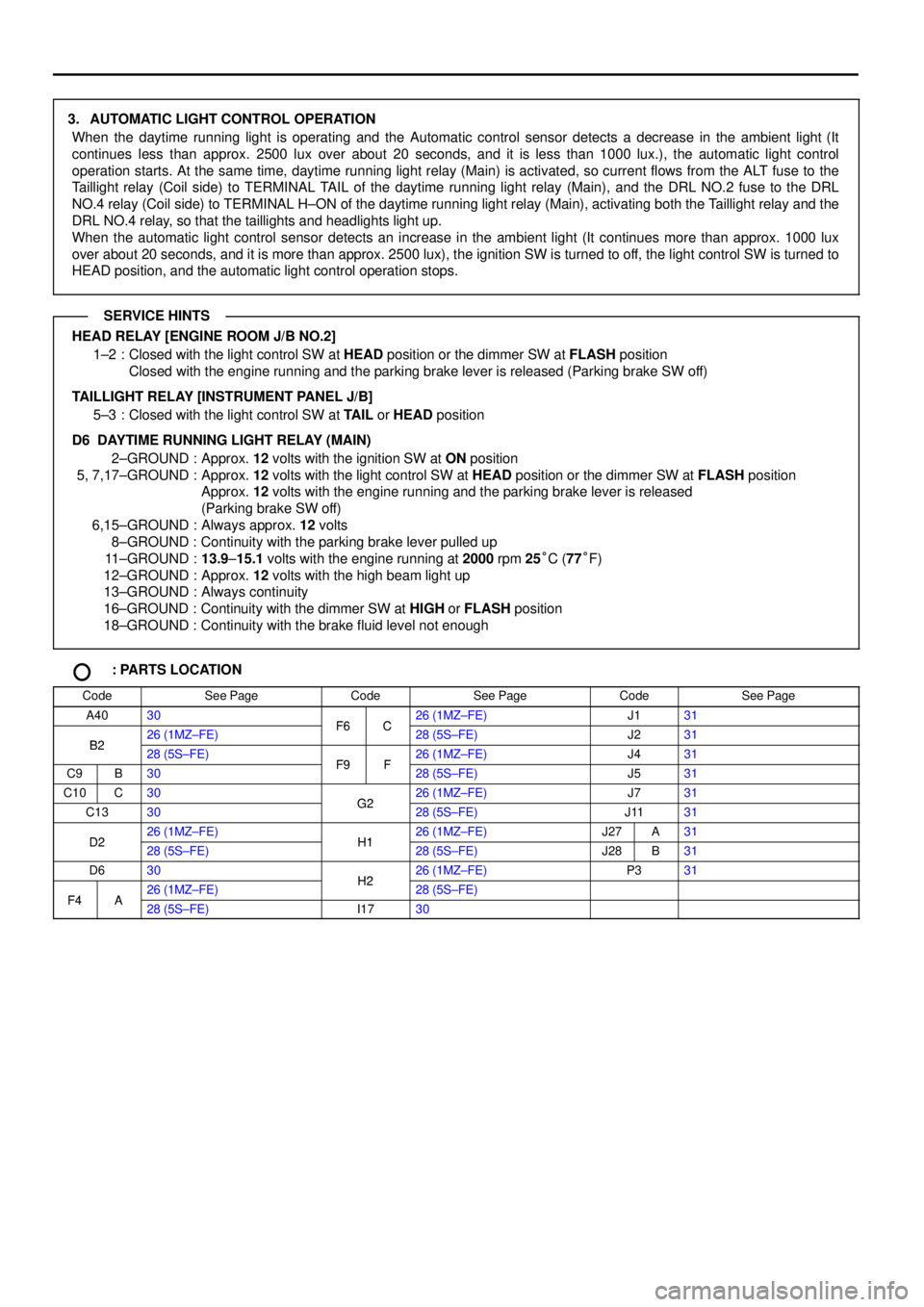
3. AUTOMATIC LIGHT CONTROL OPERATION
When the daytime running light is operating and the Automatic control sensor detects a decrease in the ambient light (It
continues less than approx. 2500 lux over about 20 seconds, and it is less than 1000 lux.), the automatic light control
operation starts. At the same time, daytime running light relay (Main) is activated, so current flows from the ALT fuse to the
Taillight relay (Coil side) to TERMINAL TAIL of the daytime running light relay (Main), and the DRL NO.2 fuse to the DRL
NO.4 relay (Coil side) to TERMINAL H±ON of the daytime running light relay (Main), activating both the Taillight relay and the
DRL NO.4 relay, so that the taillights and headlights light up.
When the automatic light control sensor detects an increase in the ambient light (It continues more than approx. 1000 lux
over about 20 seconds, and it is more than approx. 2500 lux), the ignition SW is turned to off, the light control SW is turned to
HEAD position, and the automatic light control operation stops.
HEAD RELAY [ENGINE ROOM J/B NO.2]
1±2 : Closed with the light control SW at HEAD position or the dimmer SW at FLASH position
Closed with the engine running and the parking brake lever is released (Parking brake SW off)
TAILLIGHT RELAY [INSTRUMENT PANEL J/B]
5±3 : Closed with the light control SW at TAIL or HEAD position
D6 DAYTIME RUNNING LIGHT RELAY (MAIN)
2±GROUND : Approx. 12 volts with the ignition SW at ON position
5, 7,17±GROUND : Approx. 12 volts with the light control SW at HEAD position or the dimmer SW at FLASH position
Approx. 12 volts with the engine running and the parking brake lever is released
(Parking brake SW off)
6,15±GROUND : Always approx. 12 volts
8±GROUND : Continuity with the parking brake lever pulled up
11±GROUND :13.9±15.1 volts with the engine running at 2000 rpm 25°C (77°F)
12±GROUND : Approx. 12 volts with the high beam light up
13±GROUND : Always continuity
16±GROUND : Continuity with the dimmer SW at HIGH or FLASH position
18±GROUND : Continuity with the brake fluid level not enough
: PARTS LOCATION
CodeSee PageCodeSee PageCodeSee Page
A4030F6C26 (1MZ±FE)J131
B226 (1MZ±FE)F6C28 (5S±FE)J231B228 (5S±FE)F9F26 (1MZ±FE)J431
C9B30F9F28 (5S±FE)J531
C10C30G226 (1MZ±FE)J731
C1330G228 (5S±FE)J1131
D226 (1MZ±FE)H126 (1MZ±FE)J27A31D228 (5S±FE)H128 (5S±FE)J28B31
D630H226 (1MZ±FE)P331
F4A26 (1MZ±FE)H228 (5S±FE)F4A28 (5S±FE)I1730
SERVICE HINTS
Page 1258 of 4770
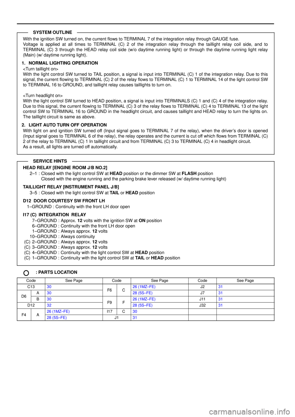
With the ignition SW turned on, the current flows to TERMINAL 7 of the integration relay through GAUGE fuse.
Voltage is applied at all times to TERMINAL (C) 2 of the integration relay through the taillight relay coil side, and to
TERMINAL (C) 3 through the HEAD relay coil side (w/o daytime running light) or through the daytime running light relay
(Main) (w/ daytime running light).
1. NORMAL LIGHTING OPERATION
With the light control SW turned to TAIL position, a signal is input into TERMINAL (C) 1 of the integration relay. Due to this
signal, the current flowing to TERMINAL (C) 2 of the relay flows to TERMINAL (C) 1 to TERMINAL 14 of the light control SW
to TERMINAL 16 to GROUND, and taillight relay causes taillights to turn on.
With the light control SW turned to HEAD position, a signal is input into TERMINALS (C) 1 and (C) 4 of the integration relay.
Due to this signal, the current flowing to TERMINAL (C) 3 of the relay flows to TERMINAL (C) 4 to TERMINAL 13 of the light
control SW to TERMINAL 16 to GROUND in the headlight circuit, and causes taillight and HEAD relay to turn the lights on.
The taillight circuit is same as above.
2. LIGHT AUTO TURN OFF OPERATION
With light on and ignition SW turned off (Input signal goes to TERMINAL 7 of the relay), when the driver's door is opened
(Input signal goes to TERMINAL 6 of the relay), the relay operates and the current is cut off which flows from TERMINAL (C)
2 of the relay to TERMINAL (C) 1 In taillight circuit and from TERMINAL (C) 3 to TERMINAL (C) 4 in headlight circuit.
As a result, all lights are turned off automatically.
HEAD RELAY [ENGINE ROOM J/B NO.2]
2±1 : Closed with the light control SW at HEAD position or the dimmer SW at FLASH position
Closed with the engine running and the parking brake lever released (w/ daytime running light)
TAILLIGHT RELAY [INSTRUMENT PANEL J/B]
3±5 : Closed with the light control SW at TAIL or HEAD position
D12 DOOR COURTESY SW FRONT LH
1±GROUND : Continuity with the front LH door open
I17 (C)
INTEGRATION RELAY
7±GROUND : Approx. 12 volts with the ignition SW at ON position
6±GROUND : Continuity with the front LH door open
1±GROUND : Always approx. 12 volts
10±GROUND : Always continuity
(C) 2±GROUND : Always approx. 12 volts
(C) 3±GROUND : Always approx. 12 volts
(C) 4±GROUND : Continuity with the light control SW at HEAD position
(C) 1±GROUND : Continuity with the light control SW at TAIL or HEAD position
: PARTS LOCATION
CodeSee PageCodeSee PageCodeSee Page
C1330F6C26 (1MZ±FE)J231
D6A30F6C28 (5S±FE)J731D6B30F9F26 (1MZ±FE)J1131
D1232F9F28 (5S±FE)J3231
F4A26 (1MZ±FE)I17C30F4A28 (5S±FE)J131
SYSTEM OUTLINE
SERVICE HINTS
Page 1266 of 4770
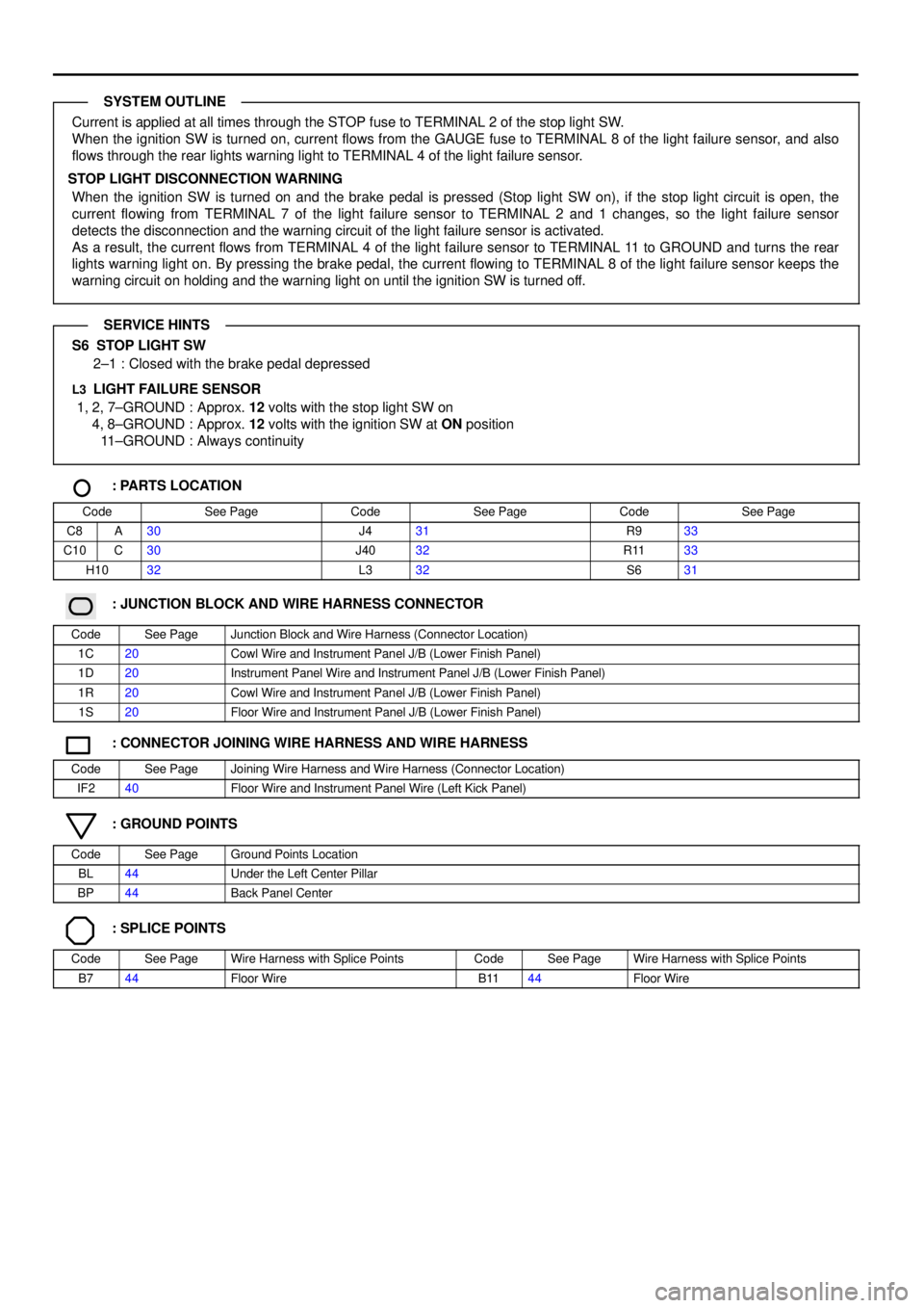
Current is applied at all times through the STOP fuse to TERMINAL 2 of the stop light SW.
When the ignition SW is turned on, current flows from the GAUGE fuse to TERMINAL 8 of the light failure sensor, and also
flows through the rear lights warning light to TERMINAL 4 of the light failure sensor.
STOP LIGHT DISCONNECTION WARNING
When the ignition SW is turned on and the brake pedal is pressed (Stop light SW on), if the stop light circuit is open, the
current flowing from TERMINAL 7 of the light failure sensor to TERMINAL 2 and 1 changes, so the light failure sensor
detects the disconnection and the warning circuit of the light failure sensor is activated.
As a result, the current flows from TERMINAL 4 of the light failure sensor to TERMINAL 11 to GROUND and turns the rear
lights warning light on. By pressing the brake pedal, the current flowing to TERMINAL 8 of the light failure sensor keeps the
warning circuit on holding and the warning light on until the ignition SW is turned off.
S6 STOP LIGHT SW
2±1 : Closed with the brake pedal depressed
L3 LIGHT FAILURE SENSOR
1, 2, 7±GROUND : Approx. 12 volts with the stop light SW on
4, 8±GROUND : Approx. 12 volts with the ignition SW at ON position
11±GROUND : Always continuity
: PARTS LOCATION
CodeSee PageCodeSee PageCodeSee Page
C8A30J431R933
C10C30J4032R1133
H1032L332S631
: JUNCTION BLOCK AND WIRE HARNESS CONNECTOR
CodeSee PageJunction Block and Wire Harness (Connector Location)
1C20Cowl Wire and Instrument Panel J/B (Lower Finish Panel)
1D20Instrument Panel Wire and Instrument Panel J/B (Lower Finish Panel)
1R20Cowl Wire and Instrument Panel J/B (Lower Finish Panel)
1S20Floor Wire and Instrument Panel J/B (Lower Finish Panel)
: CONNECTOR JOINING WIRE HARNESS AND WIRE HARNESS
CodeSee PageJoining Wire Harness and Wire Harness (Connector Location)
IF240Floor Wire and Instrument Panel Wire (Left Kick Panel)
: GROUND POINTS
CodeSee PageGround Points Location
BL44Under the Left Center Pillar
BP44Back Panel Center
: SPLICE POINTS
CodeSee PageWire Harness with Splice PointsCodeSee PageWire Harness with Splice Points
B744Floor WireB1144Floor Wire
SYSTEM OUTLINE
SERVICE HINTS
Page 1281 of 4770
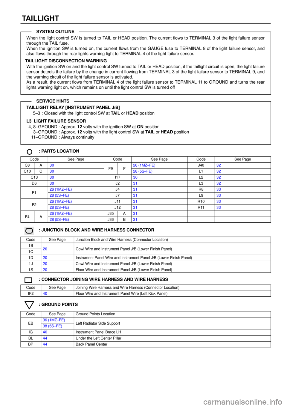
TAILLIGHT
When the light control SW is turned to TAIL or HEAD position. The current flows to TERMINAL 3 of the light failure sensor
through the TAIL fuse.
When the ignition SW is turned on, the current flows from the GAUGE fuse to TERMINAL 8 of the light failure sensor, and
also flows through the rear lights warning light to TERMINAL 4 of the light failure sensor.
TAILLIGHT DISCONNECTION WARNING
With the ignition SW on and the light control SW turned to TAIL or HEAD position, if the taillight circuit is open, the light failure
sensor detects the failure by the change in current flowing from TERMINAL 3 of the light failure sensor to TERMINAL 9, and
the warning circuit of the light failure sensor is activated.
As a result, the current flows from TERMINAL 4 of the light failure sensor to TERMINAL 11 to GROUND and turns the rear
lights warning light on, which remains on until the light control SW is turned off
TAILLIGHT RELAY [INSTRUMENT PANEL J/B]
5±3 : Closed with the light control SW at TAIL or HEAD position
L3 LIGHT FAILURE SENSOR
4, 8±GROUND : Approx. 12 volts with the ignition SW at ON position
3±GROUND : Approx. 12 volts with the light control SW at TAIL or HEAD position
11±GROUND : Always continuity
: PARTS LOCATION
CodeSee PageCodeSee PageCodeSee Page
C8A30F9F26 (1MZ±FE)J4032
C10C30F9F28 (5S±FE)L132
C1330I1730L232
D630J231L332
F126 (1MZ±FE)J431R833F128 (5S±FE)J731L933
F226 (1MZ±FE)J1131R1033F228 (5S±FE)J1231R1133
F4A26 (1MZ±FE)J35A31F4A28 (5S±FE)J36B31
: JUNCTION BLOCK AND WIRE HARNESS CONNECTOR
CodeSee PageJunction Block and Wire Harness (Connector Location)
1B20Cowl Wire and Instrument Panel J/B (Lower Finish Panel)1C20Cowl Wire and Instrument Panel J/B (Lower Finish Panel)
1D20Instrument Panel Wire and Instrument Panel J/B (Lower Finish Panel)
1J20Cowl Wire and Instrument Panel J/B (Lower Finish Panel)
1S20Floor Wire and Instrument Panel J/B (Lower Finish Panel)
: CONNECTOR JOINING WIRE HARNESS AND WIRE HARNESS
CodeSee PageJoining Wire Harness and Wire Harness (Connector Location)
IF240Floor Wire and Instrument Panel Wire (Left Kick Panel)
: GROUND POINTS
CodeSee PageGround Points Location
EB36 (1MZ±FE)Left Radiator Side SupportEB38 (5S±FE)Left Radiator Side Support
IG40Instrument Panel Brace LH
BL44Under the Left Center Pillar
BP44Back Panel Center
SYSTEM OUTLINE
SERVICE HINTS
Page 1288 of 4770
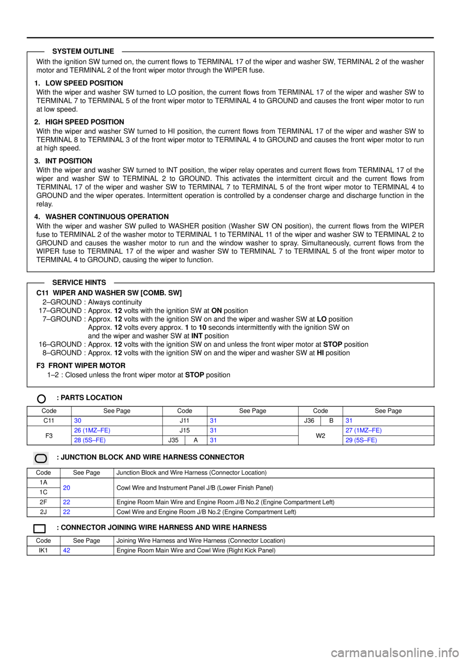
With the ignition SW turned on, the current flows to TERMINAL 17 of the wiper and washer SW, TERMINAL 2 of the washer
motor and TERMINAL 2 of the front wiper motor through the WIPER fuse.
1. LOW SPEED POSITION
With the wiper and washer SW turned to LO position, the current flows from TERMINAL 17 of the wiper and washer SW to
TERMINAL 7 to TERMINAL 5 of the front wiper motor to TERMINAL 4 to GROUND and causes the front wiper motor to run
at low speed.
2. HIGH SPEED POSITION
With the wiper and washer SW turned to HI position, the current flows from TERMINAL 17 of the wiper and washer SW to
TERMINAL 8 to TERMINAL 3 of the front wiper motor to TERMINAL 4 to GROUND and causes the front wiper motor to run
at high speed.
3. INT POSITION
With the wiper and washer SW turned to INT position, the wiper relay operates and current flows from TERMINAL 17 of the
wiper and washer SW to TERMINAL 2 to GROUND. This activates the intermittent circuit and the current flows from
TERMINAL 17 of the wiper and washer SW to TERMINAL 7 to TERMINAL 5 of the front wiper motor to TERMINAL 4 to
GROUND and the wiper operates. Intermittent operation is controlled by a condenser charge and discharge function in the
relay.
4. WASHER CONTINUOUS OPERATION
With the wiper and washer SW pulled to WASHER position (Washer SW ON position), the current flows from the WIPER
fuse to TERMINAL 2 of the washer motor to TERMINAL 1 to TERMINAL 11 of the wiper and washer SW to TERMINAL 2 to
GROUND and causes the washer motor to run and the window washer to spray. Simultaneously, current flows from the
WIPER fuse to TERMINAL 17 of the wiper and washer SW to TERMINAL 7 to TERMINAL 5 of the front wiper motor to
TERMINAL 4 to GROUND, causing the wiper to function.
C11 WIPER AND WASHER SW [COMB. SW]
2±GROUND : Always continuity
17±GROUND : Approx. 12 volts with the ignition SW at ON position
7±GROUND : Approx. 12 volts with the ignition SW on and the wiper and washer SW at LO position
Approx. 12 volts every approx. 1 to 10 seconds intermittently with the ignition SW on
and the wiper and washer SW at INT position
16±GROUND : Approx. 12 volts with the ignition SW on and unless the front wiper motor at STOP position
8±GROUND : Approx. 12 volts with the ignition SW on and the wiper and washer SW at HI position
F3 FRONT WIPER MOTOR
1±2 : Closed unless the front wiper motor at STOP position
: PARTS LOCATION
CodeSee PageCodeSee PageCodeSee Page
C1130J1131J36B31
F326 (1MZ±FE)J1531W227 (1MZ±FE)F328 (5S±FE)J35A31W229 (5S±FE)
: JUNCTION BLOCK AND WIRE HARNESS CONNECTOR
CodeSee PageJunction Block and Wire Harness (Connector Location)
1A20Cowl Wire and Instrument Panel J/B (Lower Finish Panel)1C20Cowl Wire and Instrument Panel J/B (Lower Finish Panel)
2F22Engine Room Main Wire and Engine Room J/B No.2 (Engine Compartment Left)
2J22Cowl Wire and Engine Room J/B No.2 (Engine Compartment Left)
: CONNECTOR JOINING WIRE HARNESS AND WIRE HARNESS
CodeSee PageJoining Wire Harness and Wire Harness (Connector Location)
IK142Engine Room Main Wire and Cowl Wire (Right Kick Panel)
SYSTEM OUTLINE
SERVICE HINTS
Page 1293 of 4770

POWER WINDOW
With the ignition SW turned on, current flows through the GAUGE fuse to TERMINAL 7 of the integration relay to TERMINAL
(A) 12 (w/o theft deterrent system), (B) 3 (w/ theft deterrent system) to TERMINAL 1 of the power relay to TERMINAL 2 to
GROUND, this activates the relay and the current flowing to TERMINAL 5 of the relay from the POWER fuse flows to
TERMINAL 3 of the relay to TERMINALS 10 and 11 of the power window master SW.
1. MANUAL OPERATION (DRIVER'S WINDOW)
With the ignition SW turned on and with the power window master SW (Driver's) in UP position, the current flowing from
TERMINALS 10 and 11 of the power window master SW flows to TERMINAL 1 of the master SW to TERMINAL 1 of the
power window motor to TERMINAL 2 to TERMINAL 5 of the master SW to TERMINALS 3 and 4 to GROUND and causes
the power window motor to rotate in the up direction. The window ascends only while the SW is being pushed.
In down operation, the flow of current from TERMINALS 10 and 11 of the power window master SW to TERMINAL 5 of the
master SW causes the flow of current from TERMINAL 2 of the power window motor to TERMINAL 1 to TERMINAL 1 of the
master SW to TERMINALS 3 and 4 to GROUND, flowing in the opposite detection to manual up operation and causing the
motor to rotate in reverse, lowering the window.
2. AUTO DOWN OPERATION (DRIVER'S WINDOW)
When the driver's window SW is pushed strongly to the down side, the current flowing to TERMINALS 10 and 11 of the
power window master SW flows to the down contact point and auto down contact point of the driver's SW.
This activates the relay (Down side) inside the power window master SW and the hold circuit also turns on at the same time,
so the relay (Down side) remains activated even when the SW is released.
Current flows at this time from TERMINALS 10 and 11 of the power window master SW to TERMINAL 5 to TERMINAL 2 of
the power window motor to TERMINAL 1 to TERMINAL 1 of the power window master SW to TERMINALS 3 and 4 to
GROUND, so the motor continues to operate until the driver's window is fully down.
When the driver's window finishes down operation and the hold circuit goes off, so the relay (Down side) also turns off. This
stops the current flowing from TERMINALS 10 and 11 of the power window master SW to TERMINAL 5 is cut off, so the
power window motor stops and auto down operation stops.
When the driver's SW is pulled to the up side during auto down operation, the hold circuit is turned off so the current flowing
from TERMINALS 10 and 11 of the power window master SW to TERMINAL 5 is cut off and the power window motor stops.
If the SW remains pulled up the relay (Up side) is activated, so current flows from TERMINALS 10 and 11 of the power
window master SW to TERMINAL 1 to TERMINAL 1 of the power window motor to TERMINAL 2 to TERMINAL 5 to
TERMINALS 3 and 4 to GROUND, the power window motor rotates in the up direction and manual up operation occurs
while the SW is pulled up.
3. MANUAL OPERATION (FRONT RH WINDOW)
With the power window control SW front RH pulled to the up side, the current flowing from TERMINAL 4 of the power window
control SW flows to TERMINAL 3 of the power window control SW to TERMINAL 2 of the power window motor to TERMINAL
1 to TERMINAL 1 of the power window control SW to TERMINAL 2 to TERMINAL 6 of the master SW to TERMINALS 3 and
4 to GROUND and causes the power window motor front RH to rotate in the up direction. The up operation continues only
while the power window control SW is pulled to the up side. When the window descends, the current flowing to the motor
flows in the opposite direction, from TERMINAL 1 to TERMINAL 2, and the motor rotates in reverse. When the window lock
SW is pushed to the lock side, the ground circuit to the front RH window becomes open.
As a result, even if Open/Close operation of the front RH window is tried, the current from TERMINALS 3 and 4 of the power
window master SW is not grounded and the motor does not rotate, so the front RH window can not be operated and window
lock occurs.
4. MANUAL OPERATION (REAR LH, RH WINDOW)
With the power window control SW rear LH, RH pulled to the up side, the current flowing from TERMINAL 3 of the power
window control SW flows to TERMINAL 1 of the power control SW to TERMINAL 2 of the power window motor to TERMINAL
1 to TERMINAL 5 of the power window control SW to TERMINAL 4 to TERMINAL 12 or 13 of the master SW to TERMINALS
3 and 4 to GROUND and causes the power window motor rear LH, RH to rotate in the up direction. The up operation
continues only while the power window control SW is pulled to the up side. When the window descends, the current flowing
to the motor flows in the opposite direction, from TERMINAL 1 to TERMINAL 2, and the motor rotates in reverse. When the
window lock SW is pushed to the lock side, the ground circuit to the rear LH, RH window becomes open.
As a result, even if Open/Close operation of the rear LH, RH window is tried, the current from TERMINALS 3 and 4 of the
power window master SW is not grounded and the motor does not rotate, so the rear LH, RH window can not be operated
and window lock occurs.
SYSTEM OUTLINE