Page 2722 of 4770

537 Author�: Date�:
DTC P0402 Exhaust Gas Recirculation Flow
Excessive Detected (Ex CA Spec.)
CIRCUIT DESCRIPTION
Refer to DTC P0401 (Exhaust Gas Recirculation")
DI±302
± DIAGNOSTICSENGINE (1MZ±FE)
537 Author�: Date�:
DTC P0402 Exhaust Gas Recirculation Flow
Excessive Detected (Ex CA Spec.)
CIRCUIT DESCRIPTION
Refer to DTC P0401 (Exhaust Gas Recirculation Flow Insufficient Detected) on page DI±292.
DTC No.DTC Detecting ConditionTrouble Area
P0402
When EGR cut±off, lift amount of EGR valve is
2.6 mm (0.1 in.) or more
(2 trip detection logic)
�EGR valve stuck open
�VSV for EGR open malfunction
�Short in VSV circuit for EGR
�Open or short in EGR valve position sensor circuit
�EGR valve position sensor
�ECM
See DTC P0401 (Exhaust Gas Recirculation Flow Insufficient Detected) on See page DI±292 for SYS-
TEM CHECK DRIVING PATTERN and WIRING DIAGRAM.
INSPECTION PROCEDURE
HINT:
Read freeze frame data using TOYOTA hand±held tester or OBD II scan tool. Because freeze frame records
the engine conditions when the malfunction is detected, when troubleshooting it is useful for determining
whether the vehicle was running or stopped, the engine warmed up or not, the air±fuel ratio lean or rich, etc.
at the time of the malfunction.
TOYOTA hand±held tester
1 Check connection and blockage of vacuum hose.
NG Repair or replace vacuum hose.
OK
2 Check VSV for EGR (See page DI±292, step 5).
OK Go to step 4.
NG
DI07X±06
Page 2778 of 4770
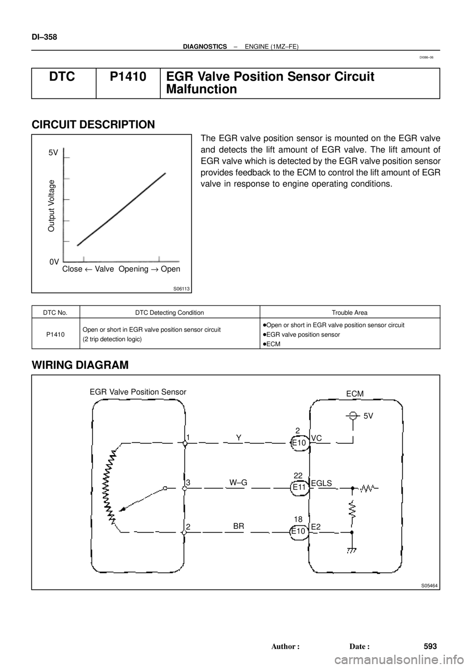
S06113
Close u Valve Opening " Open 0V 5V
Output Voltage
S05464
EGR Valve Position Sensor
3ECM
1
2Y
W±G
BRVC5V
EGLS
E2 E102
E1122
E1018 DI±358
± DIAGNOSTICSENGINE (1MZ±FE)
593 Author�: Date�:
DTC P1410 EGR Valve Position Sensor Circuit
Malfunction
CIRCUIT DESCRIPTION
The EGR valve position sensor is mounted on the EGR valve
and detects the lift amount of EGR valve. The lift amount of
EGR valve which is detected by the EGR valve position sensor
provides feedback to the ECM to control the lift amount of EGR
valve in response to engine operating conditions.
DTC No.DTC Detecting ConditionTrouble Area
P1410Open or short in EGR valve position sensor circuit
(2 trip detection logic)�Open or short in EGR valve position sensor circuit
�EGR valve position sensor
�ECM
WIRING DIAGRAM
DI086±06
Page 2896 of 4770

High
Accumulator Control Pressure
D00060
(*) Duty Ratio
The duty ratio is the ratio of the period of continuity in one cycle.
For example, if A is the period of continu")
AT5608
0
1
Electric Current (A)
High
Accumulator Control Pressure
D00060
(*) Duty Ratio
The duty ratio is the ratio of the period of continuity in one cycle.
For example, if A is the period of continuity in one cycle, and B is the period of non±continuity, then
D000621 msec./div.5 V/div.
GND Reference
Waveform between terminals SLN
+
and SLN± when engine is idling.Waveform between terminals SLN
+
and SLN± when during shift change.
1 msec./div.5 V/div.
GND DI±476
± DIAGNOSTICSAUTOMATIC TRANSAXLE (A541E)
711 Author�: Date�:
DTC P1765Linear Solenoid for Accumulator Pressure Control
Circuit Malfunction (Shift Solenoid Valve SLN)
CIRCUIT DESCRIPTION
The shift solenoid valve SLN controls the hydraulic pressure
acting on the accumulator control valve when gears are shifted
and performs smooth gear shifting.
The ECM determines optimum operating pressure according to
the signals from the throttle position sensor, vehicle speed sen-
sor and direct clutch speed sensor and controls the volume of
current flow to the solenoid valve.
The amount of current to the solenoid is controlled by the (*)
duty ratio of ECM output signals, causing a momentary change
to the hydraulic pressure acting on the clutches during gear
shifting.
When the duty ratio is high, the hydraulic pressure acting on the
clutches is low.
DTC No.DTC Detecting ConditionTrouble Area
P1765
After the engine is warmed up, the current flow to the shift
solenoid valve SLN for 1 sec or more under condition (a) or
(b):
(a) Engine speed: 500 rpm or more
(b) Park/neutral position switch: ON (P or N position)
�Open or short in shift solenoid valve SLN circuit
�Shift solenoid valve SLN
�ECM
DI02Q±02
Page 3358 of 4770
EC039±05
± EMISSION CONTROL (5S±FE)EMISSION CONTROL SYSTEM
EC±1
1399 Author�: Date�:
EMISSION CONTROL SYSTEM
PURPOSE
The emission control systems are installed to reduce the amount of HC, CO and NOx exhausted from the
engine ((3), (4) and (5)), to prevent the atmospheric release of blow±by gas±containing HC (1) and evapo-
rated fuel containing HC being released from the fuel tank (2).
The function of each system is shown in the following table.
SystemAbbreviationFunction
(1) Positive Crankcase Ventilation
(2) Evaporative Emission Control
(3) Exhaust Gas Recirculation
(4) Three±Way Catalytic Converter
(5) Sequential Multiport Fuel Injection*PCV
EVAP
EGR
TWC
SFIReduces HC
Reduces evaporated HC
Reduces NOx
Reduces HC, CO and NOx
Injects a precisely timed, optimum amount of fuel for reduced
exhaust emissions
Remark: * For inspection and repair of the SFI system, refer to the SFI section in this manual.
Page 3370 of 4770
EXHAUST GAS RECIRCULATION (EGR) SYSTEM
EC±13
1411 Author�: Date�:
HINT:
As a large amount of e")
B06539
Disconnect
S05567
Air Engine Stopped
S05566
Engine at
2,500 rpm
Air
± EMISSION CONTROL (5S±FE)EXHAUST GAS RECIRCULATION (EGR) SYSTEM
EC±13
1411 Author�: Date�:
HINT:
As a large amount of exhaust gas enters, the engine will misfire
slightly.
(g) Remove the vacuum gauge, and reconnect the vacuum
hoses to the proper locations.
(h) Inspect the EGR valve.
(1) Apply vacuum directly to the EGR valve with the en-
gine idling.
(2) Check that the engine runs rough or dies.
(3) Reconnect the vacuum hoses to the proper loca-
tions.
HINT:
As exhaust gas is increasingly recirculated, the engine will start
to misfire.
(i) Remove the SST from the DLC1.
SST 09843±18020
2. INSPECT EGR VACUUM MODULATOR
(a) Disconnect the vacuum hoses from ports P, Q and R of
the EGR vacuum modulator.
(b) Block ports P and R with your finger.
(c) Blow air into port Q, and check that the air passes through
to the air filter side freely.
(d) Start the engine, and maintain speed at 2,500 rpm.
(e) Repeat the above test. Check that there is a strong resis-
tance to air flow.
(f) Reconnect the vacuum hoses to the proper locations.
Page 3375 of 4770
EC01U±03
± EMISSION CONTROL (1MZ±FE)EMISSION CONTROL SYSTEM
EC±1
1416 Author�: Date�:
EMISSION CONTROL SYSTEM
PURPOSE
The emission control systems are installed to reduce the amount of CO, HC and NOx exhausted from the
engine ((3), (4), (5) and (6)), to prevent the atmospheric release of blow±by gas±containing HC (1) and evap-
orated fuel containing HC being released from the fuel tank (2).
The function of each system is shown in these table.
SystemAbbreviationFunction
(1) Positive Crankcase Ventilation
(2) Evaporative Emission Control
(3) Exhaust Gas Recirculation
(4) Warm Up Three±Way Catalytic Converter
(5) Three±Way Catalytic Converter
(6) Sequential Multiport Fuel Injection*PCV
EVAP
EGR
WU±TWC
TWC
SFIReduces HC
Reduces evaporated HC
Reduces NOx
Reduces HC, CO and NOx
Reduces HC, CO and NOx
Injects a precisely timed, optimum amount of fuel for reduced
exhaust emissions
Remark: * For inspection and repair of the SFI system, refer to the SF section of this manual.
Page 3395 of 4770
COMPRESSION
EM±3
1175 Author�: Date�:
COMPRESSION
INSPECTION
HINT:
If there is lack of power, excessive oil consumption or poor fuel
ec")
EM07Y±05
S05312
Compression
Gauge
± ENGINE MECHANICAL (5S±FE)COMPRESSION
EM±3
1175 Author�: Date�:
COMPRESSION
INSPECTION
HINT:
If there is lack of power, excessive oil consumption or poor fuel
economy, measure the compression pressure.
1. WARM UP AND STOP ENGINE
Allow the engine to warm up to normal operating temperature.
2. DISCONNECT IGNITION COIL CONNECTORS
3. REMOVE SPARK PLUGS (See page IG±1)
4. INSPECT CYLINDER COMPRESSION PRESSURE
(a) Insert a compression gauge into the spark plug hole.
(b) Fully open the throttle.
(c) While cranking the engine, measure the compression
pressure.
HINT:
Always use a fully charged battery to obtain engine speed of
250 rpm or more.
(d) Repeat steps (a) through (c) for each cylinder.
NOTICE:
This measurement must be done in as short a time as pos-
sible.
Compression pressure:
1,226 kPa (12.5 kgf/cm
2, 178 psi) or more
Minimum pressure: 981 kPa (10.0 kgf/cm
2, 142 psi)
Difference between each cylinder:
98 kPa (1.0 kgf/cm
2, 14 psi) or less
(e) If the cylinder compression in one or more cylinders is low,
pour a small amount of engine oil into the cylinder through
the spark plug hole and repeat steps (a) through (c) for
cylinders with low compression.
�If adding oil helps the compression, it is likely that
the piston rings and/or cylinder bore are worn or
damaged.
�If pressure stays low, a valve may be sticking or
seating is improper, or there may be leakage past
the gasket.
5. REINSTALL SPARK PLUGS (See page IG±1)
6. RECONNECT IGNITION COIL CONNECTORS
Page 3396 of 4770

(d) (e)
S05590
Turn
P03443
1 11 122
33 EM±4
± ENGINE MECHANICAL (5S±FE)VALVE CLEARANCE
1176 Author�: Date�:
VALVE CLEARANCE
INSPECTION
HINT:
Inspect and adjust the valve clear")
EM07Z±03
S05289
(c)
(d) (e)
S05590
Turn
P03443
1 11 122
33 EM±4
± ENGINE MECHANICAL (5S±FE)VALVE CLEARANCE
1176 Author�: Date�:
VALVE CLEARANCE
INSPECTION
HINT:
Inspect and adjust the valve clearance when the engine is cold.
1. REMOVE CYLINDER HEAD COVER
(a) Disconnect the 4 high±tension cords from the clamps on
the cylinder head cover.
(b) Disconnect the 4 high±tension cords from the spark
plugs.
(c) Disconnect the PCV hose from the intake manifold.
(d) Disconnect the PCV hose from the cylinder head cover.
(e) Disconnect the engine wire clamp from the mounting bolt
of the No.2 timing belt cover.
(f) Remove the cylinder head cover. (See page EM±33)
2. SET NO.1 CYLINDER TO TDC/COMPRESSION
(a) Turn the crankshaft pulley, and align its groove with timing
mark º0º of the No.1 timing belt cover.
(b) Check that the valve lifters on the No.1 cylinder are loose
and valve lifters on the No.4 are tight.
If not, turn the crankshaft one revolution (360°) and align the
mark as above.
3. INSPECT VALVE CLEARANCE
(a) Check only the valves indicated.
(1) Using a feeler gauge, measure the clearance be-
tween the valve lifter and camshaft.
(2) Record the out±of±specification valve clearance
measurements. They will be used later to determine
the required replacement adjusting shim.
Valve clearance (Cold):
Intake0.19 ± 0.29 mm (0.007 ± 0.011 in.)
Exhaust0.28 ± 0.38 mm (0.011 ± 0.015 in.)
(b) Turn the crankshaft one revolution (360°) and align the
mark as above.