Page 3533 of 4770
EM04R±05
A06651
RH Fender Apron Seal
Generator
Drive Belt
RH Engine Mounting Stay
No.2 RH Engine
Mounting BracketMAF Meter
Connector
EVAP Hose
Air Cleaner
Cap Assembly
Air Filter
EGR Vacuum Hose PS Pump Drive Belt
PS Pump
No.2 RH Engine
Mounting Stay (M/T)
�
� StayBracketFront Exhaust Pipe
� Non±reusable part: Specified torque
� Gasket
� Gasket� Gasket
64 (650, 47)32 (320, 23)
43 (440, 32)
62 (630, 46)
33 (330, 24)
64 (650, 47)
62 (630, 46)
33 (330, 24)
56 (570, 41)
N´m (kgf´cm, ft´lbf)
± ENGINE MECHANICAL (1MZ±FE)CYLINDER HEAD
EM±27
1313 Author�: Date�:
CYLINDER HEAD
COMPONENTS
Page 3535 of 4770
A05070
Timing Belt
Gasket No.2 Timing Belt Cover
RH Engine Mounting Bracket
Crankshaft
Pulley No.1 Timing Belt Cover
Gasket
Engine Wire
Protector
No.2 Idler Pulley
RH Camshaft Timing Pulley
LH Camshaft
Timing Pulley
Timing Belt TensionerTiming Belt Guide
No.2 Generator
Bracket
Dust Boot
N´m (kgf´cm, ft´lbf) : Specified torque
* For use with SST� Non±reusable part
28 (290, 21)
215 (2,200, 159)
125 (1,300, 94)
*88 (900, 65)
27 (280, 20)
43 (440, 32)
125 (1,300, 94)
± ENGINE MECHANICAL (1MZ±FE)CYLINDER HEAD
EM±29
1315 Author�: Date�:
Page 3538 of 4770

(m) (n)
S05049
(o)
(p)
(q) (s)(r)
(t) EM±32
± ENGINE MECHANICAL (1MZ±FE)CYLINDER HEAD
1318 Author�: Date�:
REMOVAL
1. DRAIN ENGINE COOLANT
2. REMOVE AIR CLE")
EM04S±05
S04528
Hexagon
Clip
A06658
(l)
(m) (n)
S05049
(o)
(p)
(q) (s)(r)
(t) EM±32
± ENGINE MECHANICAL (1MZ±FE)CYLINDER HEAD
1318 Author�: Date�:
REMOVAL
1. DRAIN ENGINE COOLANT
2. REMOVE AIR CLEANER CAP ASSEMBLY AND AIR
FILTER
3. REMOVE ENGINE RH FENDER APRON SEAL
4. REMOVE FRONT EXHAUST PIPE (See page EM±71)
5. REMOVE RH ENGINE MOUNTING STAY
6. REMOVE V±BANK COVER
(a) Using a 5 mm hexagon wrench, remove the 2 nuts.
(b) Disconnect the 2 clips, and remove the cover.
7. REMOVE HIGH±TENSION CORD SET
(See page IG±7)
8. REMOVE AIR INTAKE CHAMBER ASSEMBLY
(a) Disconnect the accelerator cable.
(b) Disconnect the A/T throttle cable.
(c) Disconnect the throttle position sensor connector.
(d) Disconnect the IAC valve connector.
(e) Disconnect the EGR gas temperature sensor connector.
(f) Disconnect the EGR valve position sensor connector.
(g) Disconnect the VSV connector for the ACIS.
(h) Disconnect the VSV connector for the EVAP.
(i) Disconnect the VSV connector for the EGR.
(j) Disconnect the DLC1 from the bracket on the intake air
control valve.
(k) Remove the 2 nuts, and disconnect the PS pressure tube
from the No.1 engine hanger.
(l) Disconnect the PCV hose from the PCV valve on the RH
cylinder head.
(m) Disconnect the ground strap and cable from the intake air
control valve for the ACIS.
(n) Disconnect the ground cable from the air intake chamber.
(o) Disconnect the brake booster vacuum hose from the air
intake chamber.
(p) Disconnect the 2 water bypass hoses from the throttle
body.
(q) Disconnect the air assist hose from the throttle body.
(r) Disconnect the purge hose from the pipe on emission
control valve set.
(s) Disconnect the 2 vacuum hoses from the vacuum tank for
the ACIS.
Page 3545 of 4770
CYLINDER HEAD
EM±39
1325 Author�: Date�:
(2) Secur")
P12873Main Gear
Sub±GearService Bolt Intake
P12958
Intake
7
85
6
3
41
2
9
10
P12886
7
85 6
3 41 2
9 10 Exhaust
P12596
± ENGINE MECHANICAL (1MZ±FE)CYLINDER HEAD
EM±39
1325 Author�: Date�:
(2) Secure the exhaust camshaft sub±gear to the main
gear with a service bolt.
Recommended service bolt:
Thread diameter6 mm
Thread pitch1.0 mm
Bolt length16 ± 20 mm (0.63 ± 0.79 in.)
HINT:
When removing the camshaft, make sure that the torsional
spring force of the sub±gear has been eliminated by the above
operation.
(b) Uniformly loosen and remove the 10 bearing cap bolts, in
several passes, in the sequence shown.
(c) Remove the 5 bearing caps and intake camshaft.
(d) Remove the exhaust camshaft.
(1) Uniformly loosen and remove the 10 bearing cap
bolts, in several passes, in the sequence shown.
(2) Remove the 5 bearing caps, oil seal and exhaust
camshaft.
HINT:
�Arrange the camshafts in the correct order.
�Arrange the bearing caps in the correct order.
33. DISASSEMBLE EXHAUST CAMSHAFTS
(a) Mount the hexagonal wrench head portion of the cam-
shaft in a vise.
NOTICE:
Be careful not to damage the camshaft.
Page 3561 of 4770
Adhesive
P12572
Protrusion
P12869
Flush
P12719
SST
± ENGINE MECHANICAL (1MZ±FE)CYLINDER HEAD
EM±55
1341 Author�: Date�:
REASSEMBLY
HINT:
�Thoroughly c")
EM04V±04
P1151110 ± 15 mm (0.39 ± 0.59 in.)Adhesive
P12572
Protrusion
P12869
Flush
P12719
SST
± ENGINE MECHANICAL (1MZ±FE)CYLINDER HEAD
EM±55
1341 Author�: Date�:
REASSEMBLY
HINT:
�Thoroughly clean all parts to be assembled.
�Before installing the parts, apply new engine oil to all slid-
ing and rotating surfaces.
�Replace all gaskets and oil seals with new ones.
1. INSTALL SPARK PLUG TUBES
HINT:
When using a new cylinder head, spark plug tubes must be
installed.
(a) Apply adhesive to the end of the spark plug tube.
Adhesive:
Part No. 08833±00070, THREE BOND 1324
or equivalent
(b) Using a press, press in a new spark plug tube until there
is 42.4 ± 43.4 mm (1.669 ± 1.709 in.) protruding from the
camshaft bearing cap installation surface of the cylinder
head.
NOTICE:
Avoid pressing a new spark plug tube in too far by measur-
ing the amount of the protrusion while pressing.
2. INSTALL PCV PIPES
HINT:
When using a new cylinder head, PCV pipe must be installed.
Using a wooden block and hammer, tap in a new PCV pipe until
its top side is flush with the cylinder head edge.
NOTICE:
Be careful not to damage the cylinder head edge.
3. INSTALL VALVES
(a) Using SST, push in a new oil seal.
SST 09201±41020
Page 3564 of 4770
P12814
Recessed Head Bolt
8 mm Hexagon Wrench
Front
P12595
Z09320
(3)
(2)
(1)
P12590
EM±58
± ENGINE MECHANICAL (1MZ±FE)CYLINDER HEAD
1344 Author�: Date�:
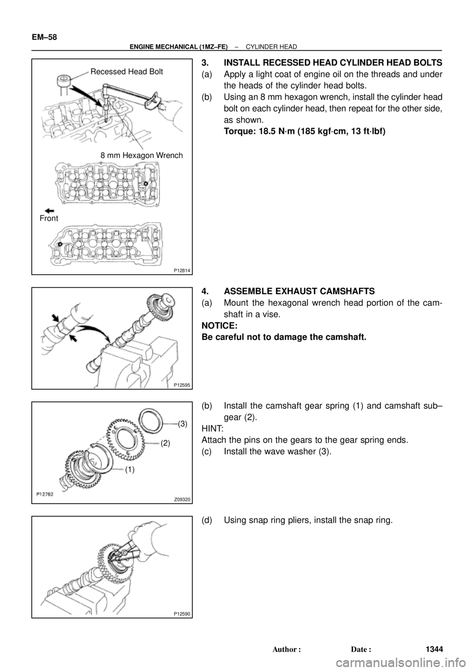
3. INSTALL RECESSED HEAD CYLINDER HEAD BOLTS
(a) Apply a light coat of engine oil on the threads and under
the heads of the cylinder head bolts.
(b) Using an 8 mm hexagon wrench, install the cylinder head
bolt on each cylinder head, then repeat for the other side,
as shown.
Torque: 18.5 N´m (185 kgf´cm, 13 ft´lbf)
4. ASSEMBLE EXHAUST CAMSHAFTS
(a) Mount the hexagonal wrench head portion of the cam-
shaft in a vise.
NOTICE:
Be careful not to damage the camshaft.
(b) Install the camshaft gear spring (1) and camshaft sub±
gear (2).
HINT:
Attach the pins on the gears to the gear spring ends.
(c) Install the wave washer (3).
(d) Using snap ring pliers, install the snap ring.
Page 3573 of 4770
CYLINDER HEAD
EM±67
1353 Author�: Date�:
(b) Connect the fuel inlet hose to the fuel filter.
CAUTI")
S04791
8 mm Hexagon
Wrench
S04790
Chamber Stay
Engine
Hanger EGR
Pipe
± ENGINE MECHANICAL (1MZ±FE)CYLINDER HEAD
EM±67
1353 Author�: Date�:
(b) Connect the fuel inlet hose to the fuel filter.
CAUTION:
Perform connecting operations of the fuel tube connector
(quick type) after observing the precaution.
(See page SF±1)
(c) Connect the heater hose to the intake manifold.
29. RETIGHTEN WATER OUTLET MOUNTING BOLTS
AND NUTS
Tighten the 2 bolts and 2 nuts.
Torque: 15 N´m (150 kgf´cm, 11 ft´lbf)
30. INSTALL AIR INTAKE CHAMBER ASSEMBLY
(a) Using an 8 mm hexagon wrench, install a new gasket and
the air intake chamber assembly with the 2 bolts and 2
nuts. Uniformly tighten the bolts and nuts in several
passes.
Torque: 43 N´m (440 kgf´cm, 32 ft´lbf)
(b) Install 2 new gaskets and No.2 EGR pipe with the 4 nuts.
Torque: 12 N´m (120 kgf´cm, 9 ft´lbf)
(c) Install the No.1 engine hanger with the 2 bolts.
Torque: 39 N´m (400 kgf´cm, 29 ft´lbf)
(d) Install the air intake chamber stay with the 2 bolts.
Torque: 19.5 N´m (200 kgf´cm, 14 ft´lbf)
(e) Connect the PCV hose to the PCV valve on the RH cylin-
der head.
(f) Connect the ground strap and cable to the intake air con-
trol valve for the ACIS.
(g) Connect the ground cable and strap with the nut.
Torque: 14.5 N´m (145 kgf´cm, 10 ft´lbf)
(h) Connect the ground cable to the air intake chamber.
(i) Connect the brake booster vacuum hose to the air intake
chamber.
(j) Connect the 2 water bypass hoses to the throttle body.
(k) Connect the air assist hose to the throttle body.
(l) Connect the purge hose to the emission control valve set.
(m) Connect the 2 vacuum hoses to the vacuum tank for the
ACIS.
(n) Connect the engine wire clamp to the emission control
valve set.
(o) Install the PS pressure tube with the 2 nuts.
(p) Connect the throttle position sensor connector.
(q) Connect the IAC valve connector.
(r) Connect the EGR gas temperature sensor connector.
(s) Connect the EGR valve position sensor connector.
(t) Connect the VSV connector for the ACIS.
(u) Connect the VSV connecter for the EVAP.
(v) Connect the VSV connector for the EGR.
Page 3574 of 4770
EM±68
± ENGINE MECHANICAL (1MZ±FE)CYLINDER HEAD
1354 Author�: Date�:
(w) Connect the DLC1 to the bracket on the intake air control
valve.
(x) Connect the accelerator cable.
(y) Connect the A/T throttle cable.
31. INSTALL HIGH±TENSION CORD SET
32. INSTALL V±BANK COVER
33. INSTALL RH ENGINE MOUNTING STAY
(See page EM±76)
34. INSTALL AIR FILTER AND AIR CLEANER CAP
ASSEMBLY
35. INSTALL RH FENDER APRON SEAL
36. INSTALL FRONT EXHAUST PIPE
(See page EM±76)
37. FILL WITH ENGINE COOLANT
38. START ENGINE AND CHECK FOR LEAKS
39. VEHICLE ROAD TEST
Check for abnormal noise, shock, slippage, correct shift points
and smoothly operation.
40. RECHECK ENGINE COOLANT LEVEL