Page 3688 of 4770

± INTRODUCTIONFOR ALL OF VEHICLES
IN±17
17 Author�: Date�:
2. FOR VEHICLES EQUIPPED WITH A CATALYTIC CONVERTER
CAUTION:
If large amount of unburned gasoline flows into the converter, it may overheat and create a fire haz-
ard. To prevent this, observe the following precautions and explain them to your customer.
(a) Use only unleaded gasoline.
(b) Avoid prolonged idling.
Avoid running the engine at idle speed for more than 20 minutes.
(c) Avoid spark jump test.
(1) Perform spark jump test only when absolutely necessary. Perform this test as rapidly as possible.
(2) While testing, never race the engine.
(d) Avoid prolonged engine compression measurement.
Engine compression tests must be done as rapidly as possible.
(e) Do not run engine when fuel tank is nearly empty.
This may cause the engine to misfire and create an extra load on the converter.
(f) Avoid coasting with ignition turned off.
(g) Do not dispose of used catalyst along with parts contaminated with gasoline or oil.
3. IF VEHICLE IS EQUIPPED WITH MOBILE COMMUNICATION SYSTEM
For vehicles with mobile communication systems such as two±way radios and cellular telephones, observe
the following precautions.
(1) Install the antenna as far as possible away from the ECU and sensors of the vehicle's electronic
system.
(2) Install the antenna feeder at least 20 cm (7.87 in.) away from the ECU and sensors of the ve-
hicle's electronic systems. For details about ECU and sensors locations, refer to the section on
the applicable component.
(3) Avoid winding the antenna feeder together with other wiring as much as possible, and also avoid
running the antenna feeder parallel with other wire harnesses.
(4) Check that the antenna and feeder are correctly adjusted.
(5) Do not install powerful mobile communications system.
Page 3716 of 4770
OIL AND FILTER
1648 Author�: Date�:
REPLACEMENT
CAUTION:
�Prolonged and repeated contact with mineral oil will
result in the removal of natura")
LU03I±03
S05318
SST
S05319
LU±2
± LUBRICATION (5S±FE)OIL AND FILTER
1648 Author�: Date�:
REPLACEMENT
CAUTION:
�Prolonged and repeated contact with mineral oil will
result in the removal of natural fats from the skin,
leading to dryness, irritation and dermatitis. In addi-
tion, used engine oil contains potentially harmful
contaminants which may cause skin cancer.
�Care should be taken, therefore, when changing en-
gine oil to minimize the frequency and length of time
your skin is exposed to used engine oil. Protective
clothing and gloves that cannot be penetrated by oil
should be worn. The skin should be thoroughly
washed with soap and water, or use water±less hand
cleaner, to remove any used engine oil. Do not use
gasoline, thinners, or solvents.
�In order to preserve the environment, used oil and
used oil filters must be disposed of only at desig-
nated disposal sites.
1. DRAIN ENGINE OIL
(a) Remove the oil filler cap.
(b) Remove the oil drain plug, and drain the oil into a contain-
er.
2. REPLACE OIL FILTER
(a) Using SST, remove the oil filter.
SST 09228±06501
(b) Clean the oil filter contact surface on the oil filter mount-
ing.
(c) Lubricate the filter rubber gasket with clean engine oil.
(d) Tighten the oil filter by hand until the rubber gasket con-
tacts the seat of the filter mounting.
Page 3718 of 4770
LU03J±03
S05595
Engine Moving Control Rod
No.2 RH Engine Mounting Bracket
Generator Drive Belt
RH Front Fender Apron Seal
PS Pump Drive Belt
Exhaust Pipe Bracket
Oil Pan InsulatorGround Strap Connector
No.2 Rear End Plate
No.2 Exhaust
Manifold Stay
(TMMK Made)
(TMC Made)LH Stiffener Plate
� Gasket
Bracket
Front Exhaust Pipe
StayBracket� Gasket
N´m (kgf´cm, ft´lbf): Specified torque
� Non±reusable part
64 (650, 47)
52 (530, 38)
62 (630, 46)56 (570, 41) 64 (650, 47)
��
� LU±4
± LUBRICATION (5S±FE)OIL PUMP
1650 Author�: Date�:
OIL PUMP
COMPONENTS
Page 3732 of 4770
LU03T±03
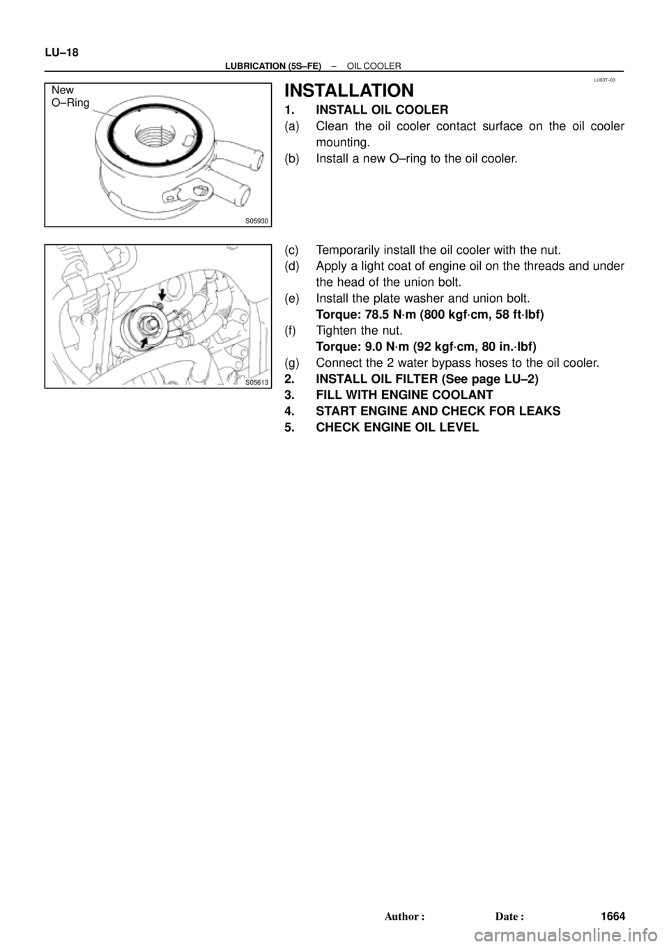
S05930
New
O±Ring
S05613
LU±18
± LUBRICATION (5S±FE)OIL COOLER
1664 Author�: Date�:
INSTALLATION
1. INSTALL OIL COOLER
(a) Clean the oil cooler contact surface on the oil cooler
mounting.
(b) Install a new O±ring to the oil cooler.
(c) Temporarily install the oil cooler with the nut.
(d) Apply a light coat of engine oil on the threads and under
the head of the union bolt.
(e) Install the plate washer and union bolt.
Torque: 78.5 N´m (800 kgf´cm, 58 ft´lbf)
(f) Tighten the nut.
Torque: 9.0 N´m (92 kgf´cm, 80 in.´lbf)
(g) Connect the 2 water bypass hoses to the oil cooler.
2. INSTALL OIL FILTER (See page LU±2)
3. FILL WITH ENGINE COOLANT
4. START ENGINE AND CHECK FOR LEAKS
5. CHECK ENGINE OIL LEVEL
Page 3737 of 4770
LU027±04
B06398
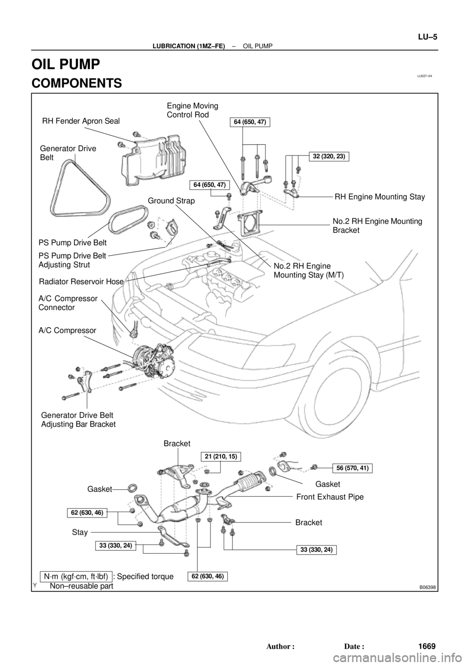
� Gasket RH Fender Apron Seal
PS Pump Drive Belt
A/C Compressor
Connector
A/C Compressor
No.2 RH Engine
Mounting Stay (M/T) Engine Moving
Control Rod
RH Engine Mounting Stay
No.2 RH Engine Mounting
Bracket
Ground Strap
Bracket
Front Exhaust Pipe
Stay
�
PS Pump Drive Belt
Adjusting Strut
Generator Drive Belt
Adjusting Bar Bracket
� Gasket
�
64 (650, 47)
62 (630, 46)
33 (330, 24)
21 (210, 15)
56 (570, 41)
64 (650, 47)
32 (320, 23)
62 (630, 46)
33 (330, 24)
N´m (kgf´cm, ft´lbf) : Specified torque
� Non±reusable part
Bracket
Generator Drive
Belt
Radiator Reservoir Hose
± LUBRICATION (1MZ±FE)OIL PUMP
LU±5
1669 Author�: Date�:
OIL PUMP
COMPONENTS
Page 3738 of 4770
B06384
No.2 Timing Belt CoverTiming Belt
Gasket
Timing Belt Guide
No.2 Generator
Bracket RH Engine Mounting Bracket
Crankshaft
PulleyGasket
Engine Wire
Protector
RH Camshaft Timing Pulley
No.2 Idler Pulley
Crankshaft
Timing PulleyDust Boot
Timing Belt Plate Plate Washer
�
Timing Belt Tensioner
N´m (kgf´cm, ft´lbf) : Specified torque
� Non±reusable part No.1 Timing Belt Cover
LH Camshaft
Timing Pulley
No.1 Idler Pulley
� Precoated part
* For use with SST
28 (290, 21)
215 (2,200, 159)
125 (1,300, 94)*88 (900, 65)43 (440, 32)
34 (350, 25)
27 (280, 20)
125 (1,300, 94)
LU±6
± LUBRICATION (1MZ±FE)OIL PUMP
1670 Author�: Date�:
Page 3750 of 4770
OIL PUMP
1682 Author�: Date�:
(b) Apply seal packing to the No.2 oil pan as shown in the il-
lustration.
Seal packing:
Part No. 08826�")
P12568
A
A
BB
Seal Width
4 ± 5 mm LU±18
± LUBRICATION (1MZ±FE)OIL PUMP
1682 Author�: Date�:
(b) Apply seal packing to the No.2 oil pan as shown in the il-
lustration.
Seal packing:
Part No. 08826±00080 or equivalent
�Install a nozzle that has been cut to a 4 ± 5 mm (0.16
± 0.20 in.) opening.
HINT:
Avoid applying an excessive amount to the surface.
�Parts must be assembled within 3 minutes of ap-
plication. Otherwise the material must be removed
and reapplied.
�Immediately remove nozzle from the tube and rein-
stall cap.
(c) Install the No.2 oil pan with the 10 bolts and 2 nuts. Uni-
formly tighten the bolts and nuts in several passes.
Torque: 8 N´m (80 kgf´cm, 69 in.´lbf)
7. INSTALL A/C COMPRESSOR HOUSING BRACKET
Torque: 25 N´m (250 kgf´cm, 18 ft´lbf)
8. INSTALL NO.3 TIMING BELT COVER
(See page EM±21)
9. INSTALL TIMING PULLEYS (See page EM±21)
10. INSTALL TIMING BELT (See page EM±21)
11. INSTALL ADJUSTING STRUT AND PS PUMP DRIVE
BELT
(a) Temporarily install the adjusting strut with the bolt and the
nut.
(b) Install the drive belt with the pivot and adjusting bolts.
Torque: 43.1 N´m (440 kgf´cm, 32 ft´lbf)
(c) Tighten the nut.
Torque: 43.1 N´m (440 kgf´cm, 32 ft´lbf)
12. INSTALL A/C COMPRESSOR (See page AC±47)
13. INSTALL GENERATOR DRIVE BELT
(See page CH±16)
14. INSTALL FRONT EXHAUST PIPE BRACKET TO
NO.1 OIL PAN
Torque: 21 N´m (210 kgf´cm, 15 ft´lbf)
15. INSTALL FRONT EXHAUST PIPE (See page EM±76)
16. REMOVE RH FENDER APRON SEAL
17. REMOVE RH FRONT WHEEL
18. FILL ENGINE WITH OIL
19. START ENGINE AND CHECK FOR LEAKS
20. RECHECK ENGINE OIL LEVEL
Page 3752 of 4770

MA002±11
MA±2
± MAINTENANCEINSIDE VEHICLE
45 Author�: Date�:
INSIDE VEHICLE
GENERAL MAINTENANCE
These are maintenance and inspection items which are considered to be the owner's responsibility.
They can be done by the owner or they can have them done at a service shop.
These items include those which should be checked on a daily basis, those which, in most cases, do not
require (special) tools and those which are considered to be reasonable for the owner to do.
Items and procedures for general maintenance are as follows.
1. GENERAL NOTES
�Maintenance items may vary from country to country. Check the owner's manual supplement in which
the maintenance schedule is shown.
�Every service item in the periodic maintenance schedule must be performed.
�Periodic maintenance service must be performed according to whichever interval in the periodic main-
tenance schedule occurs first, the odometer reading (miles) or the time interval (months).
�Maintenance service after the last period should be performed at the same interval as before unless
otherwise noted.
�Failure to do even one item an cause the engine to run poorly and increase exhaust emissions.
2. LIGHTS
(a) Check that the headlights, stop lights, taillights, turn signal lights, and other lights are all working.
(b) Check the headlight aim.
3. WARNING LIGHTS AND BUZZERS
Check that all warning lights and buzzers function properly.
4. HORN
Check that it is working.
5. WINDSHIELD GLASS
Check for scratches, pits or abrasions.
6. WINDSHIELD WIPER AND WASHER
(a) Check operation of the wipers and washer.
(b) Check that the wipers do not streak.
7. WINDSHIELD DEFROSTER
Check that air comes out from the defroster outlet when operating the heater or air conditioner.
8. REAR VIEW MIRROR
Check that it is mounted securely.
9. SUN VISORS
Check that they move freely and are mounted securely.
10. STEERING WHEEL
Check that it has the specified freeplay. Be alert for changes in steering condition, such as hard steering,
excessive freeplay or strange noises.
11. SEATS
(a) Check that the seat adjusters operate smoothly.
(b) Check that all latches lock securely in any position.
(c) Check that the head restraints move up and down smoothly and that the locks hold securely in any
latch position.
(d) For fold±down seat backs, check that the latches lock securely.
12. SEAT BELTS
(a) Check that the seat belt system such as the buckles, retractors and anchors operate properly and
smoothly.
(b) Check that the belt webbing is not cut, frayed, worn or damaged.