Page 3432 of 4770
CYLINDER HEAD
1212 Author�: Date�:
25. DISASSEMBLE EXHAUST CAMSHAFT
(a) Mount the camshaft")
P05613
S01665
SST
Service
Bolt
S01666
EM7558
6 10
192 8 3
74 5
S05971
Pry EM±40
± ENGINE MECHANICAL (5S±FE)CYLINDER HEAD
1212 Author�: Date�:
25. DISASSEMBLE EXHAUST CAMSHAFT
(a) Mount the camshaft in a vise.
NOTICE:
Be careful not to damage the camshaft.
(b) Using SST, turn the sub±gear clockwise, and remove the
service bolt.
SST 09960±10010 (09962±01000, 09963±00500)
(c) Using snap ring pliers, remove the snap ring.
(d) Remove the wave washer, camshaft sub±gear and gear
spring.
26. REMOVE CYLINDER HEAD
(a) Disconnect the camshaft position sensor connector.
(b) Remove the 2 bolts holding the water bypass pipe to the
cylinder head.
(c) Uniformly loosen and remove the 10 cylinder head bolts
in several passes, in the sequence shown.
NOTICE:
Cylinder head warpage or cracking could result from re-
moving bolts in incorrect order.
(d) Lift the cylinder head from the dowels on the cylinder
block, and place the cylinder head on wooden blocks on
a bench.
HINT:
If the cylinder head is off, pry between the cylinder head and cyl-
inder block with a screwdriver.
NOTICE:
Be careful not to damage the contact surfaces of the cylin-
der head and cylinder block.
Page 3446 of 4770
CYLINDER HEAD
1226 Author�: Date�:
4. ASSEMBLE EXHAUST CAMSHA")
P05617
Z02838
Wave Washer
Sub±Gear
Gear Spring
S01666
S01664
SST
Turn Sub±Gear
Service
BoltMain Gear EM±54
± ENGINE MECHANICAL (5S±FE)CYLINDER HEAD
1226 Author�: Date�:
4. ASSEMBLE EXHAUST CAMSHAFT
(a) Mount the camshaft in a vise.
NOTICE:
Be careful not to damage the camshaft.
(b) Install the camshaft gear spring, camshaft sub±gear and
wave washer.
HINT:
Align the pins on the gears with the spring ends.
(c) Using snap ring pliers, install the snap ring.
(d) Using SST, align the holes of the camshaft drive gear and
sub±gear by turning camshaft sub±gear clockwise, and
install a service bolt.
SST 09960±10010 (09962±01000, 09963±00500)
(e) Align the gear teeth of the drive gear and sub±gear, and
tighten the service bolt.
5. INSTALL CAMSHAFTS
NOTICE:
Since the thrust clearance of the camshaft is small, the
camshaft must be kept level while it is being installed. If the
camshaft is not kept level, the portion of the cylinder head
receiving the shaft thrust may crack or be damaged, caus-
ing the camshaft to seize or break. To avoid this, the follow-
ing steps should be carried out.
Page 3458 of 4770
A02188
Engine Moving Control Rod
Engine and
Transaxle Assembly
Front Engine
Mounting Insulator
RH Drive Shaft
Lower Suspension ArmLH Drive Shaft No.2 RH Engine
Mounting BracketRear Engine
mounting
Insulator
Transaxle
Shift
Control
Cable
(A/T)
Tie Rod End
Lock CapTransaxle Shift
Control Cable
Clutch Release Cylinder and Tube Engine Wire
��Starter M/T
N´m (kgf´cm, ft´lbf)
64 (650, 47)
64 (650, 47)
127 (1,300, 94)
52 (530, 38)
64 (650, 47)
66 (670, 49)
49 (500, 36)
64 (650, 47)
64 (650, 47)
64 (650, 47)
294 (3,000, 217)
TMC Made
80 (820, 59)
TMMK Made
44 (450, 32) for Silver Color
66 (670, 49) for Green Color
: Specified torque
� Non±reusable part
EM±66
± ENGINE MECHANICAL (5S±FE)ENGINE UNIT
1238 Author�: Date�:
Page 3463 of 4770
S05250
Connector
S05246
S05254
M/T
S04616
A/T
S05247
± ENGINE MECHANICAL (5S±FE)ENGINE UNIT
EM±71
1243 Author�: Date�:
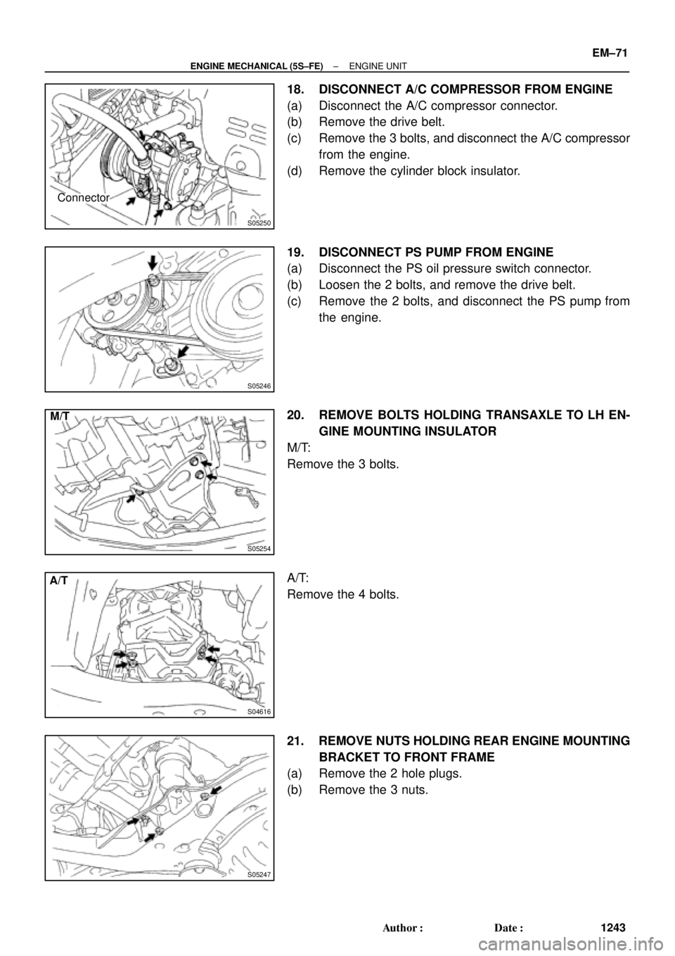
18. DISCONNECT A/C COMPRESSOR FROM ENGINE
(a) Disconnect the A/C compressor connector.
(b) Remove the drive belt.
(c) Remove the 3 bolts, and disconnect the A/C compressor
from the engine.
(d) Remove the cylinder block insulator.
19. DISCONNECT PS PUMP FROM ENGINE
(a) Disconnect the PS oil pressure switch connector.
(b) Loosen the 2 bolts, and remove the drive belt.
(c) Remove the 2 bolts, and disconnect the PS pump from
the engine.
20. REMOVE BOLTS HOLDING TRANSAXLE TO LH EN-
GINE MOUNTING INSULATOR
M/T:
Remove the 3 bolts.
A/T:
Remove the 4 bolts.
21. REMOVE NUTS HOLDING REAR ENGINE MOUNTING
BRACKET TO FRONT FRAME
(a) Remove the 2 hole plugs.
(b) Remove the 3 nuts.
Page 3464 of 4770
ENGINE UNIT
1244 Author�: Date�:
22. REMOVE BOLTS HOLDING FRONT ENGINE MOUNT-
ING INSULATOR TO FRONT FRAME
Remove the 3 bolts.
23.")
S05248
S05323
S05249
A06578
Lift EM±72
± ENGINE MECHANICAL (5S±FE)ENGINE UNIT
1244 Author�: Date�:
22. REMOVE BOLTS HOLDING FRONT ENGINE MOUNT-
ING INSULATOR TO FRONT FRAME
Remove the 3 bolts.
23. ATTACH ENGINE SLING DEVICE TO ENGINE HANG-
ERS
Attach the engine chain hoist to the engine hangers.
CAUTION:
Do not attempt to hang the engine by hooking the chain to
any other part.
24. REMOVE ENGINE MOVING CONTROL ROD
Remove the 3 bolts and control rod.
25. REMOVE ENGINE AND TRANSAXLE ASSEMBLY
FROM VEHICLE
(a) Lift the engine out of the vehicle slowly and carefully.
NOTICE:
Make sure the engine is clear of all wiring, hoses and
cables.
(b) Place the engine and transaxle assembly onto the stand.
26. REMOVE FRONT ENGINE MOUNTING INSULATOR
FROM ENGINE
Remove the 4 bolts and mounting insulator.
27. REMOVE REAR ENGINE MOUNTING INSULATOR
FROM ENGINE
Remove the 4 bolts, the mounting insulator.
28. REMOVE NO.2 RH ENGINE MOUNTING BRACKET
FROM ENGINE
Remove the 3 bolts and mounting bracket.
29. A/T:
DISCONNECT THROTTLE CABLE FROM THROTTLE
BODY
Page 3469 of 4770
ENGINE UNIT
EM±77
1249 Author�: Date�:
Torque:
37 N´m (380 kgf´cm, 27 ft´lbf) for M/T
42 N´m (430 kgf´cm, 31 ft´lbf) for A/T
(d) TMC Made:
Tighten the nut holding t")
± ENGINE MECHANICAL (5S±FE)ENGINE UNIT
EM±77
1249 Author�: Date�:
Torque:
37 N´m (380 kgf´cm, 27 ft´lbf) for M/T
42 N´m (430 kgf´cm, 31 ft´lbf) for A/T
(d) TMC Made:
Tighten the nut holding the manifold stay to the cylinder
block.
Torque: 58 N´m (591 kgf´cm, 43 ft´lbf)
(e) TMMK Made:
Tighten the bolt holding the manifold stay to the cylinder
block.
Torque: 42 N´m (425 kgf´cm, 31 ft´lbf)
(f) Tighten the nut holding the manifold stay to the exhaust
manifold.
Torque: 42 N´m (425 kgf´cm, 31 ft´lbf)
12. INSTALL NO.1 EXHAUST MANIFOLD STAY
Install the manifold stay with the 2 bolts.
Torque: 42 N´m (425 kgf´cm, 31 ft´lbf)
13. CONNECT CONNECTORS
(a) Connect the VSS connector.
(b) M/T:
Connect the back±up light switch connector.
(c) A/T:
Connect the PNP switch connector.
(d) A/T:
Connect the 2 solenoid connectors.
14. A/T:
INSTALL STARTER (See page ST±19)
15. A/T:
INSTALL THROTTLE CABLE TO THROTTLE BODY
16. INSTALL NO.2 RH ENGINE MOUNTING BRACKET TO
ENGINE
Install the mounting insulator with the 3 bolts.
Torque: 52 N´m (530 kgf´cm, 38 ft´lbf)
17. INSTALL REAR ENGINE MOUNTING INSULATOR TO
ENGINE
Install the mounting insulator with the 4 bolts.
Torque: 64 N´m (650 kgf´cm, 47 ft´lbf)
18. INSTALL FRONT ENGINE MOUNTING INSULATOR TO
ENGINE
Install the mounting insulator with the 4 bolts.
Torque: 64 N´m (650 kgf´cm, 47 ft´lbf)
Page 3470 of 4770
ENGINE UNIT
1250 Author�: Date�:
19. INSTALL ENGINE AND TRANSAXLE ASSEMBLY IN
VEHICLE
(a) Attach the engine sling devic")
A06577
Lower
S05249
S05248
S05247
S05254
M/T EM±78
± ENGINE MECHANICAL (5S±FE)ENGINE UNIT
1250 Author�: Date�:
19. INSTALL ENGINE AND TRANSAXLE ASSEMBLY IN
VEHICLE
(a) Attach the engine sling device to the engine hangers.
(b) Lower the engine into the engine compartment.
Tilt the transaxle downward, and lower the engine.
(c) Keep the engine level, and attach front and rear mount-
ings to the front frame.
20. INSTALL ENGINE MOVING CONTROL ROD
Install the control rod with the 3 bolts.
Torque: 64 N´m (650 kgf´cm, 47 ft´lbf)
21. INSTALL BOLTS HOLDING FRONT ENGINE MOUNT-
ING INSULATOR TO FRONT FRAME
Install the 3 bolts.
Torque:
TMC made
80 N´m (820 kgf´cm, 59 ft´lbf)
TMMK made
44 N´m (450 kgf´cm, 32 ft´lbf) for silver color
66 N´m (670 kgf´cm, 49 ft´lbf) for green color
22. INSTALL NUTS HOLDING REAR ENGINE MOUNTING
INSULATOR TO FRONT FRAME
(a) Install the 3 nuts.
Torque: 66 N´m (670 kgf´cm, 49 ft´lbf)
(b) Install the 2 hole plugs.
23. INSTALL BOLTS HOLDING LH ENGINE MOUNTING
INSULATOR TO FRONT FRAME
M/T:
Install the 3 bolts.
Torque: 64 N´m (650 kgf´cm, 47 ft´lbf)
Page 3497 of 4770
CYLINDER BLOCK
EM±105
1277 Author�: Date�:
(b) Using a micrometer, measure the piston diameter at right
angle")
A07352
20.5 mm
S01546
SST
S05573
Cut Position
Pry
S05572
SST
± ENGINE MECHANICAL (5S±FE)CYLINDER BLOCK
EM±105
1277 Author�: Date�:
(b) Using a micrometer, measure the piston diameter at right
angles to the piston pin center line, 20.5 mm (0.807 in.)
from the piston head.
(c) Calculate the amount of each cylinder is to be rebored as
follows:
Size to be rebored = P + C ± H
P = Piston diameter
C = Piston oil clearance
0.175 ± 0.195 mm (0.0068 ± 0.0076 in.)
H = Allowance for honing
0.02 mm (0.0008 in.) or less
(d) Bore and hone the cylinders to calculated dimensions.
Maximum honing: 0.02 mm (0.0008 in.)
NOTICE:
Excess honing will destroy the finished roundness.
3. REPLACE CRANKSHAFT FRONT OIL SEAL
HINT:
There are 2 methods ((a) and (b)) to replace the oil seal.
(a) If the oil pump is removed from the cylinder block:
(1) Using a screwdriver and hammer, tap out the oil
seal.
(2) Using SST and a hammer, tap in a new oil seal until
its surface is flush with the oil pump body edge.
SST 09226±10010
(3) Apply MP grease to the oil seal lip.
(b) If the oil pump is installed to the cylinder block:
(1) Using a knife, cut off the oil seal lip.
(2) Using a screwdriver, pry out the oil seal.
NOTICE:
Be careful not to damage the crankshaft. Tape the screw-
driver tip.
(3) Apply MP grease to a new oil seal lip.
(4) Using SST and a hammer, tap in the oil seal until its
surface is flush with the oil pump body edge.
SST 09226±10010