Page 4015 of 4770
± SERVICE SPECIFICATIONSMANUAL TRANSAXLE (S51)
SS±53
216 Author�: Date�:
Engine mount bracket x Transaxle5253038
Reverse shift arm bracket1818513
No.3 shift fork x Shift fork shaft1818513
Lock ball assembly2930022
Filler and Drain plugs4950036
Back±up light switch4445033
Differential side bearing retainer1818513
Release bearing retainer7.47565 in.´lbf
Straight screw plug131309
Vehicle speed sensor driven gear5.45548 in.´lbf
Clutch release fork support3940029
Page 4017 of 4770

SS0AT±01
± SERVICE SPECIFICATIONSAUTOMATIC TRANSAXLE (A140E)
SS±55
218 Author�: Date�:
TORQUE SPECIFICATION
Part tightenedN´mkgf´cmft´lbf
Transaxle x Starter4243031
Transaxle x Rear end plate2525018
Transaxle x No.1 exhaust pipe support bracket1919514
Transaxle x Engine6667048
Torque converter clutch x Drive plate2728020
Body x Front lower brace Bolt
Nut181
361,850
370134
27
Body x Rear lower brace 19 mm head bolt
14 mm head bolt
Nut181
32
361,850
330
370134
24
27
Front suspension member x FR engine mounting TMC made
TMMK made: Green color bolt
TMMK made: Silver color bolt80
66
44820
670
45059
48
32
Front suspension member x RR engine mounting6667048
Front suspension member x LH engine mounting8082059
Transaxle x LH engine mounting6465047
Front suspension member x Steering return pipe mounting bracket101007
Front suspension member x Stabilizer bar bracket1919514
Stabilizer bar x Stabilizer bar link3940029
Ball joint x Lower suspension arm1271,30094
Steering gear housing set bolt x Nut1811,850134
Exhaust manifold x Front exhaust pipe6263046
Front suspension member x Exhaust pipe No.1 support bracket3333024
Front exhaust pipe x Center exhaust pipe5657041
No.1 exhaust pipe support bracket x Exhaust pipe clamp3333024
Axle hub nut2943,000217
Steering knuckle x Tie rod end4950036
Vehicle speed sensor x Transaxle1616012
Park/neutral position switch x Transaxle Bolt
Nut5.4
6.955
7048 in.´lbf
61 in.´lbf
Park/neutral position switch x Control shaft lever131309
Control shaft lever x Control cable1515011
Oil pan x Drain plug4950036
Oil pan x Transaxle4.95043 in.´lbf
Valve body x Manual valve body101007
Valve body x Transaxle101007
Drive shaft center bearing lock bolt3233024
Stiffener plate Front side
Rear side42
39430
40031
29
Exhaust manifold stay Front side
Rear side42
39430
40031
29
Page 4019 of 4770

SS0BM±01
± SERVICE SPECIFICATIONSAUTOMATIC TRANSAXLE (A541E)
SS±57
220 Author�: Date�:
TORQUE SPECIFICATION
Part tightenedN´mkgf´cmft´lbf
Front engine front mounting insulator x Front frame assemblyTMC:
TMMK:
Green color bolt
Silver color bolt80
66
44820
670
45059
48
32
Rear engine mounting insulator x Front frame assembly8082059
LH transaxle mounting insulator x Transaxle6465047
Engine mounting absorber x Front frame assembly4849035
Transaxle x Engine 17 mm bolt6667048
Transaxle x Engine 12 mm bolt4849035
Torque converter clutch x Drive plate4142030
Valve body x Transaxle case1111 08
Oil strainer x Valve body1111 08
Oil pan x Transaxle case7.88069 in.´lbf
Oil pan drain plug4950036
Park/Neutral position switch x Transaxle case (bolt)5.45548 in.´lbf
Park/Neutral position switch (nut)6.97061 in.´lbf
B3 apply pipe retainer1111 08
Connector clamp1111 08
Manual valve body x Transaxle case1111 08
Detent spring x Manual valve body1111 08
Oil pipe bracket101007
Steering gear housing x Front suspension member1811,850134
Stabilizer bar bracket1919514
Vehicle speed sensor x Transaxle case4.95043 in.´lbf
Direct clutch speed sensor x Transaxle case1111 08
Transfer lubrication apply pipe retainer1111 08
Exhaust manifold bracket x Transaxle case Except California
California20
34200
35014
25
Exhaust manifold plate Except California
California20
34200
35014
25
Front frame x Body 19 mm1811,850134
Front frame x Body 14 mm3233024
Front frame x Body Nut3637027
Exhaust front pipe x Exhaust center pipe5657041
Exhaust manifold x Exhaust front pipe6263046
Exhaust front pipe support stay x Exhaust front pipe support bracket3333024
Exhaust pipe support x Front frame3333024
Starter x Torque converter clutch housing3940029
Transaxle control shaft lever x Park/neutral position switch1515011
Throttle cable adjusting nut1515011
Drive plate x Crankshaft8385061
Shift control cable x Transaxle control shaft lever1515011
Throttle cable retaining plate set bolt5.45548 in.´lbf
Shift solenoid valve No.1, No.2, SL, SLN x Valve body6.66758 in.´lbf
Page 4036 of 4770
FI2553
SST
S04600
Fuel
Pump
Connector
S05326
Plug SF±2
± SFI (5S±FE)SFI SYSTEM
1435 Author�: Date�:
(b) When installing the battery, be especially careful not to in-
correctly connect the positive (+) and negative (±) cables.
(c) Do not permit parts to receive a severe impact during re-
moval or installation. Handle all SFI parts carefully, espe-
cially the ECM.
(d) Be careful during troubleshooting as there are numerous
transistor circuit, and even slight terminal contact can
cause further troubles.
(e) Do not open the ECM cover.
(f) When inspecting during rainy weather, take care to pre-
vent entry of water. Also, when washing the engine
compartment, prevent water from getting on the SFI parts
and wiring connectors.
(g) Parts should be replaced as an assembly.
(h) Care should be taken when pulling out and inserting wir-
ing connectors.
(1) Release the lock and pull out the connector, pulling
on the connectors.
(2) Fully insert the connector and check that it is locked.
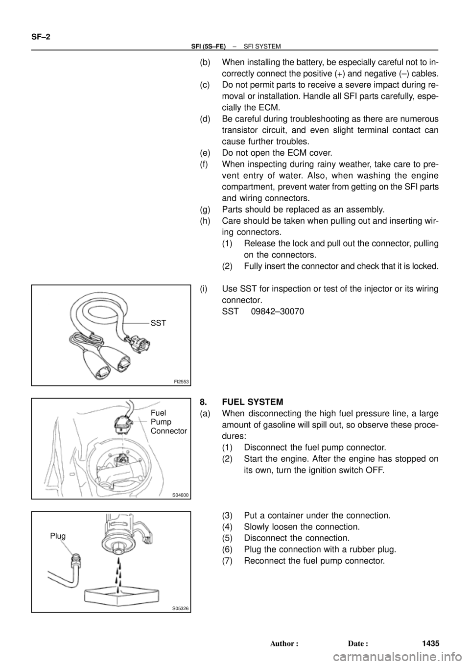
(i) Use SST for inspection or test of the injector or its wiring
connector.
SST 09842±30070
8. FUEL SYSTEM
(a) When disconnecting the high fuel pressure line, a large
amount of gasoline will spill out, so observe these proce-
dures:
(1) Disconnect the fuel pump connector.
(2) Start the engine. After the engine has stopped on
its own, turn the ignition switch OFF.
(3) Put a container under the connection.
(4) Slowly loosen the connection.
(5) Disconnect the connection.
(6) Plug the connection with a rubber plug.
(7) Reconnect the fuel pump connector.
Page 4039 of 4770
S05050
Click Sound
S05331
± SFI (5S±FE)SFI SYSTEM
SF±5
1438 Author�: Date�:
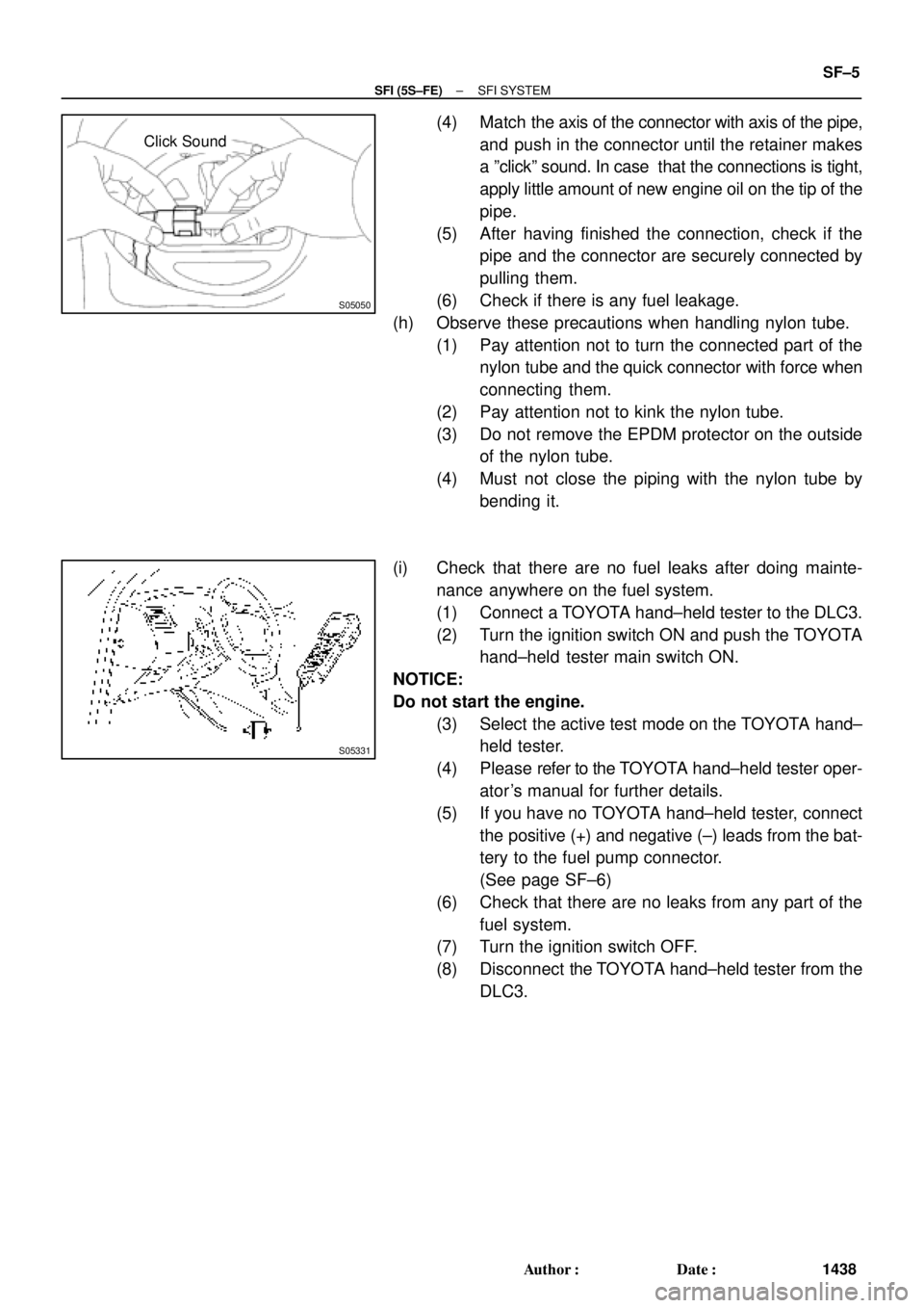
(4) Match the axis of the connector with axis of the pipe,
and push in the connector until the retainer makes
a ºclickº sound. In case that the connections is tight,
apply little amount of new engine oil on the tip of the
pipe.
(5) After having finished the connection, check if the
pipe and the connector are securely connected by
pulling them.
(6) Check if there is any fuel leakage.
(h) Observe these precautions when handling nylon tube.
(1) Pay attention not to turn the connected part of the
nylon tube and the quick connector with force when
connecting them.
(2) Pay attention not to kink the nylon tube.
(3) Do not remove the EPDM protector on the outside
of the nylon tube.
(4) Must not close the piping with the nylon tube by
bending it.
(i) Check that there are no fuel leaks after doing mainte-
nance anywhere on the fuel system.
(1) Connect a TOYOTA hand±held tester to the DLC3.
(2) Turn the ignition switch ON and push the TOYOTA
hand±held tester main switch ON.
NOTICE:
Do not start the engine.
(3) Select the active test mode on the TOYOTA hand±
held tester.
(4) Please refer to the TOYOTA hand±held tester oper-
ator 's manual for further details.
(5) If you have no TOYOTA hand±held tester, connect
the positive (+) and negative (±) leads from the bat-
tery to the fuel pump connector.
(See page SF±6)
(6) Check that there are no leaks from any part of the
fuel system.
(7) Turn the ignition switch OFF.
(8) Disconnect the TOYOTA hand±held tester from the
DLC3.
Page 4056 of 4770
SF0DI±03
S05289
(c)
(e)
(d)
B06353
B06354
SF±22
± SFI (5S±FE)INJECTOR
1455 Author�: Date�:
REMOVAL
1. REMOVE CYLINDER HEAD COVER
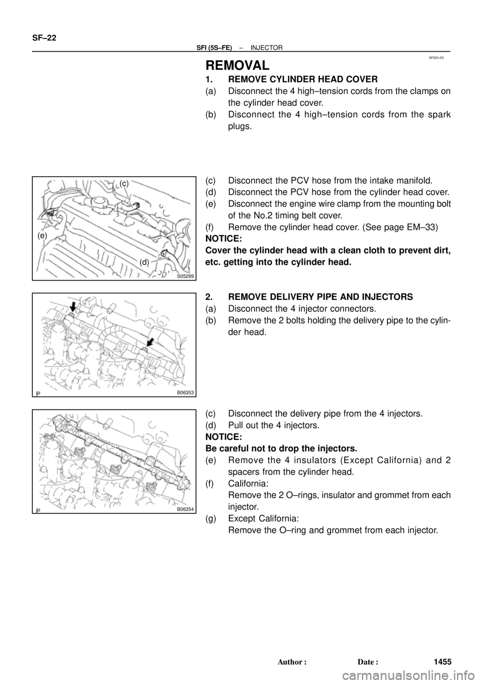
(a) Disconnect the 4 high±tension cords from the clamps on
the cylinder head cover.
(b) Disconnect the 4 high±tension cords from the spark
plugs.
(c) Disconnect the PCV hose from the intake manifold.
(d) Disconnect the PCV hose from the cylinder head cover.
(e) Disconnect the engine wire clamp from the mounting bolt
of the No.2 timing belt cover.
(f) Remove the cylinder head cover. (See page EM±33)
NOTICE:
Cover the cylinder head with a clean cloth to prevent dirt,
etc. getting into the cylinder head.
2. REMOVE DELIVERY PIPE AND INJECTORS
(a) Disconnect the 4 injector connectors.
(b) Remove the 2 bolts holding the delivery pipe to the cylin-
der head.
(c) Disconnect the delivery pipe from the 4 injectors.
(d) Pull out the 4 injectors.
NOTICE:
Be careful not to drop the injectors.
(e) Remove the 4 insulators (Except California) and 2
spacers from the cylinder head.
(f) California:
Remove the 2 O±rings, insulator and grommet from each
injector.
(g) Except California:
Remove the O±ring and grommet from each injector.
Page 4060 of 4770
B06352
S05976
Upward
Turn
Connector
B06351
Gray
Brown No.1
No.2
No.3
No.4
S05289
(b)
(c) (d) SF±26
± SFI (5S±FE)INJECTOR
1459 Author�: Date�:
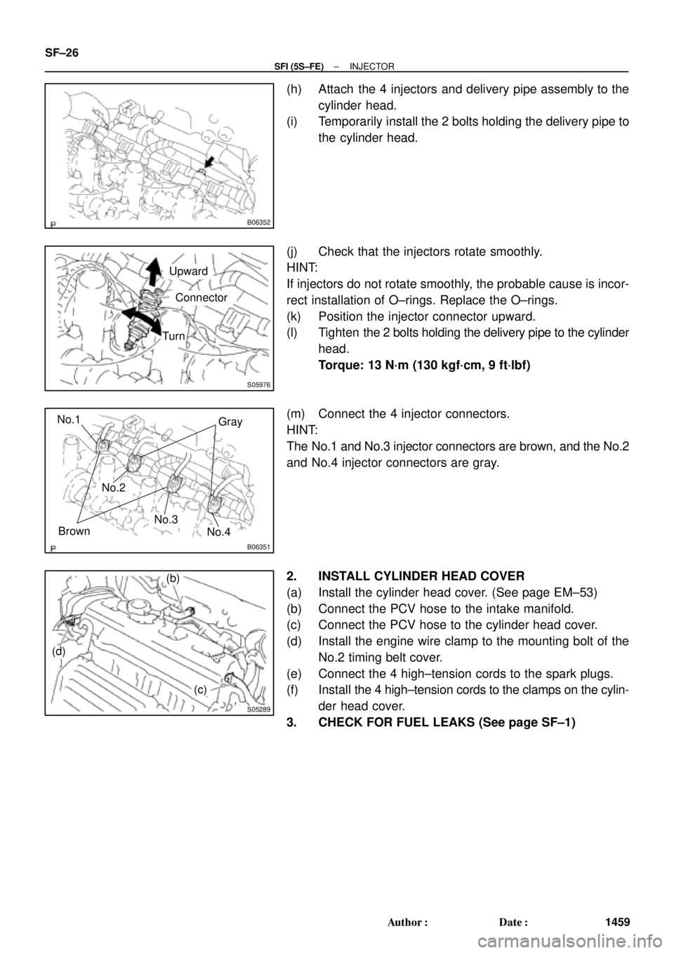
(h) Attach the 4 injectors and delivery pipe assembly to the
cylinder head.
(i) Temporarily install the 2 bolts holding the delivery pipe to
the cylinder head.
(j) Check that the injectors rotate smoothly.
HINT:
If injectors do not rotate smoothly, the probable cause is incor-
rect installation of O±rings. Replace the O±rings.
(k) Position the injector connector upward.
(l) Tighten the 2 bolts holding the delivery pipe to the cylinder
head.
Torque: 13 N´m (130 kgf´cm, 9 ft´lbf)
(m) Connect the 4 injector connectors.
HINT:
The No.1 and No.3 injector connectors are brown, and the No.2
and No.4 injector connectors are gray.
2. INSTALL CYLINDER HEAD COVER
(a) Install the cylinder head cover. (See page EM±53)
(b) Connect the PCV hose to the intake manifold.
(c) Connect the PCV hose to the cylinder head cover.
(d) Install the engine wire clamp to the mounting bolt of the
No.2 timing belt cover.
(e) Connect the 4 high±tension cords to the spark plugs.
(f) Install the 4 high±tension cords to the clamps on the cylin-
der head cover.
3. CHECK FOR FUEL LEAKS (See page SF±1)
Page 4102 of 4770
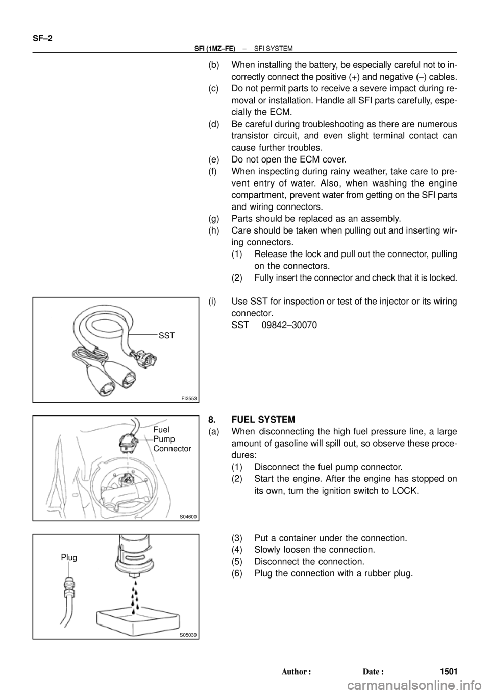
FI2553
SST
S04600
Fuel
Pump
Connector
S05039
Plug
SF±2
± SFI (1MZ±FE)SFI SYSTEM
1501 Author�: Date�:
(b) When installing the battery, be especially careful not to in-
correctly connect the positive (+) and negative (±) cables.
(c) Do not permit parts to receive a severe impact during re-
moval or installation. Handle all SFI parts carefully, espe-
cially the ECM.
(d) Be careful during troubleshooting as there are numerous
transistor circuit, and even slight terminal contact can
cause further troubles.
(e) Do not open the ECM cover.
(f) When inspecting during rainy weather, take care to pre-
vent entry of water. Also, when washing the engine
compartment, prevent water from getting on the SFI parts
and wiring connectors.
(g) Parts should be replaced as an assembly.
(h) Care should be taken when pulling out and inserting wir-
ing connectors.
(1) Release the lock and pull out the connector, pulling
on the connectors.
(2) Fully insert the connector and check that it is locked.
(i) Use SST for inspection or test of the injector or its wiring
connector.
SST 09842±30070
8. FUEL SYSTEM
(a) When disconnecting the high fuel pressure line, a large
amount of gasoline will spill out, so observe these proce-
dures:
(1) Disconnect the fuel pump connector.
(2) Start the engine. After the engine has stopped on
its own, turn the ignition switch to LOCK.
(3) Put a container under the connection.
(4) Slowly loosen the connection.
(5) Disconnect the connection.
(6) Plug the connection with a rubber plug.