Page 1951 of 4770
AUTOMATIC TRANSAXLE UNIT
AX±23
1943 Author�: Date�:
REMOVAL
1. REMOVE BATTERY
2. REMOVE AIR CLEANER ASSEMBLY
3. REMOVE THROT")
AX03Y±01
Q00225
Q09982
Q10287
Q00075
Q10028
± AUTOMATIC TRANSAXLE (A541E)AUTOMATIC TRANSAXLE UNIT
AX±23
1943 Author�: Date�:
REMOVAL
1. REMOVE BATTERY
2. REMOVE AIR CLEANER ASSEMBLY
3. REMOVE THROTTLE CABLE FROM THROTTLE
BODY
Torque: 15 N´m (150 kgf´cm, 11 ft´lbf)
4. w/ Cruise Control:
REMOVE CRUISE CONTROL ACTUATOR
(a) Disconnect the connector.
(b) Remove the 3 bolts and disconnect cruise control actua-
tor with the bracket.
Torque: 13 N´m (130 kgf´cm, 9 ft´lbf)
5. DISCONNECT GROUND CABLE
6. DISCONNECT VEHICLE SPEED SENSOR CONNEC-
TOR
7. DISCONNECT DIRECT CLUTCH SPEED SENSOR
CONNECTOR
8. DISCONNECT PARK/NEUTRAL POSITION SWITCH
CONNECTOR
9. DISCONNECT SOLENOID CONNECTOR
10. DISCONNECT SHIFT CONTROL CABLE
(a) Remove the nut and disconnect the shift control cable
from the park/neutral position switch.
Torque: 15 N´m (150 kgf´cm, 11 ft´lbf)
(b) Remove the clip and disconnect the shift control cable.
11. REMOVE 2 ENGINE MOUNTING ABSORBER BOLTS
Torque: 48 N´m (490 kgf´cm, 35 ft´lbf)
Page 1952 of 4770
AUTOMATIC TRANSAXLE UNIT
1944 Author�: Date�:
12. REMOVE 2 FRONT SIDE ENGINE MOUNTING BOLTS
Torque:
TMC Made: 80 N´m (820 kgf´cm, 59")
Q06478
Q10286
Q06530
Q10038
AX±24
± AUTOMATIC TRANSAXLE (A541E)AUTOMATIC TRANSAXLE UNIT
1944 Author�: Date�:
12. REMOVE 2 FRONT SIDE ENGINE MOUNTING BOLTS
Torque:
TMC Made: 80 N´m (820 kgf´cm, 59 ft´lbf)
TMMK Made:
Green color bolt: 66 N´m (670 kgf´cm, 48 ft´lbf)
Silver color bolt: 44 N´m (440 kgf´cm, 32 ft´lbf)
13. REMOVE STARTER AND A/T SHIFT CABLE CLAMP
(a) Disconnect the connector and remove the nut.
(b) Remove the 2 bolts, starter and A/T shift cable clamp.
Torque: 39 N´m (400 kgf´cm, 29 ft´lbf)
14. REMOVE EXHAUST MANIFOLD BRACKET MOUNT-
ING BOLT
Torque:
Except California: 20 N´m (200 kgf´cm, 15 ft´lbf)
California: 34 N´m (350 kgf´cm, 25 ft´lbf)
15. REMOVE 5 TRANSAXLE±TO±ENGINE BOLTS AND
DISCONNECT GROUND TERMINAL
Torque: 66 N´m (670 kgf´cm, 48 ft´lbf)
16. REMOVE ENGINE HOOD
(a) Disconnect the washer pipe.
(b) Remove the 4 bolts and engine hood.
Torque: 26 N´m (265 kgf´cm, 19 ft´lbf)
17. RAISE AND SUPPORT VEHICLE SECURELY
18. REMOVE FRONT WHEELS
Torque: 103 N´m (1,050 kgf´cm, 76 ft´lbf)
19. REMOVE DIFFERENTIAL FLUID DRAIN PLUG AND
GASKET
HINT:
At the time of installation, please refer to the following item.
Replace the used gasket with a new gasket.
20. DRAIN DIFFERENTIAL FLUID
21. REMOVE LH AND RH ENGINE SIDE COVERS
22. REMOVE LH AND RH FRONT DRIVE SHAFTS
(See page SA±25)
Page 1953 of 4770
AUTOMATIC TRANSAXLE UNIT
AX±25
1945 Author�: Date�:
23. REMOVE ENGINE UNDER FRONT COVER AND NO.4
CENTER ENGINE UNDER COVER
24. REMOVE EXHAUST FRONT")
Q10030
Q10341
Q00235
± AUTOMATIC TRANSAXLE (A541E)AUTOMATIC TRANSAXLE UNIT
AX±25
1945 Author�: Date�:
23. REMOVE ENGINE UNDER FRONT COVER AND NO.4
CENTER ENGINE UNDER COVER
24. REMOVE EXHAUST FRONT PIPE
(a) Remove the 2 bolts and exhaust front pipe support stay.
Torque: 33 N´m (330 kgf´cm, 24 ft´lbf)
(b) Remove the 4 nuts.
Torque: 62 N´m (630 kgf´cm, 46 ft´lbf)
HINT:
At the time of installation, please refer to the following item.
Replace the used nuts with new once.
(c) Remove the 2 bolts and nuts.
Torque: 56 N´m (570 kgf´cm, 41 ft´lbf)
HINT:
At the time of installation, please refer to the following item.
Replace the used nuts with new once.
(d) Remove the 2 exhaust front pipe clamp bolts and exhaust
front pipe.
Torque: 33 N´m (330 kgf´cm, 24 ft´lbf)
(e) Remove the 3 gaskets.
HINT:
At the time of installation, please refer to the following item.
Replace the used gaskets with new once.
(f) Remove the 2 nuts, 2 bolts, exhaust front pipe support
bracket and hole cover.
Torque:
Exhaust front pipe support bracket mounting nut:
21 N´m (210 kgf´cm, 15 ft´lbf)
Hole plug mounting bolt:
20 N´m (200 kgf´cm, 15 ft´lbf)
25. REMOVE FRONT SIDE ENGINE MOUNTING INSULA-
TOR BOLT
Torque:
TMC Made:
80 N´m (820 kgf´cm, 59 ft´lbf)
TMMK Made:
Green color bolt: 66 N´m (670 kgf´cm, 48 ft´lbf)
Silver color bolt: 44 N´m (440 kgf´cm, 32 ft´lbf)
Page 1954 of 4770
Q10027
Q10071
Q10034
Q10035
Q10040
AX±26
± AUTOMATIC TRANSAXLE (A541E)AUTOMATIC TRANSAXLE UNIT
1946 Author�: Date�:
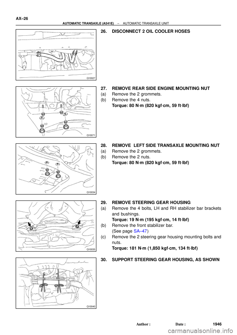
26. DISCONNECT 2 OIL COOLER HOSES
27. REMOVE REAR SIDE ENGINE MOUNTING NUT
(a) Remove the 2 grommets.
(b) Remove the 4 nuts.
Torque: 80 N´m (820 kgf´cm, 59 ft´lbf)
28. REMOVE LEFT SIDE TRANSAXLE MOUNTING NUT
(a) Remove the 2 grommets.
(b) Remove the 2 nuts.
Torque: 80 N´m (820 kgf´cm, 59 ft´lbf)
29. REMOVE STEERING GEAR HOUSING
(a) Remove the 4 bolts, LH and RH stabilizer bar brackets
and bushings.
Torque: 19 N´m (195 kgf´cm, 14 ft´lbf)
(b) Remove the front stabilizer bar.
(See page SA±47)
(c) Remove the 2 steering gear housing mounting bolts and
nuts.
Torque: 181 N´m (1,850 kgf´cm, 134 ft´lbf)
30. SUPPORT STEERING GEAR HOUSING, AS SHOWN
Page 1955 of 4770
P19478
Engine
Hanger
Q06479
Q10041
Q10037
± AUTOMATIC TRANSAXLE (A541E)AUTOMATIC TRANSAXLE UNIT
AX±27
1947 Author�: Date�:
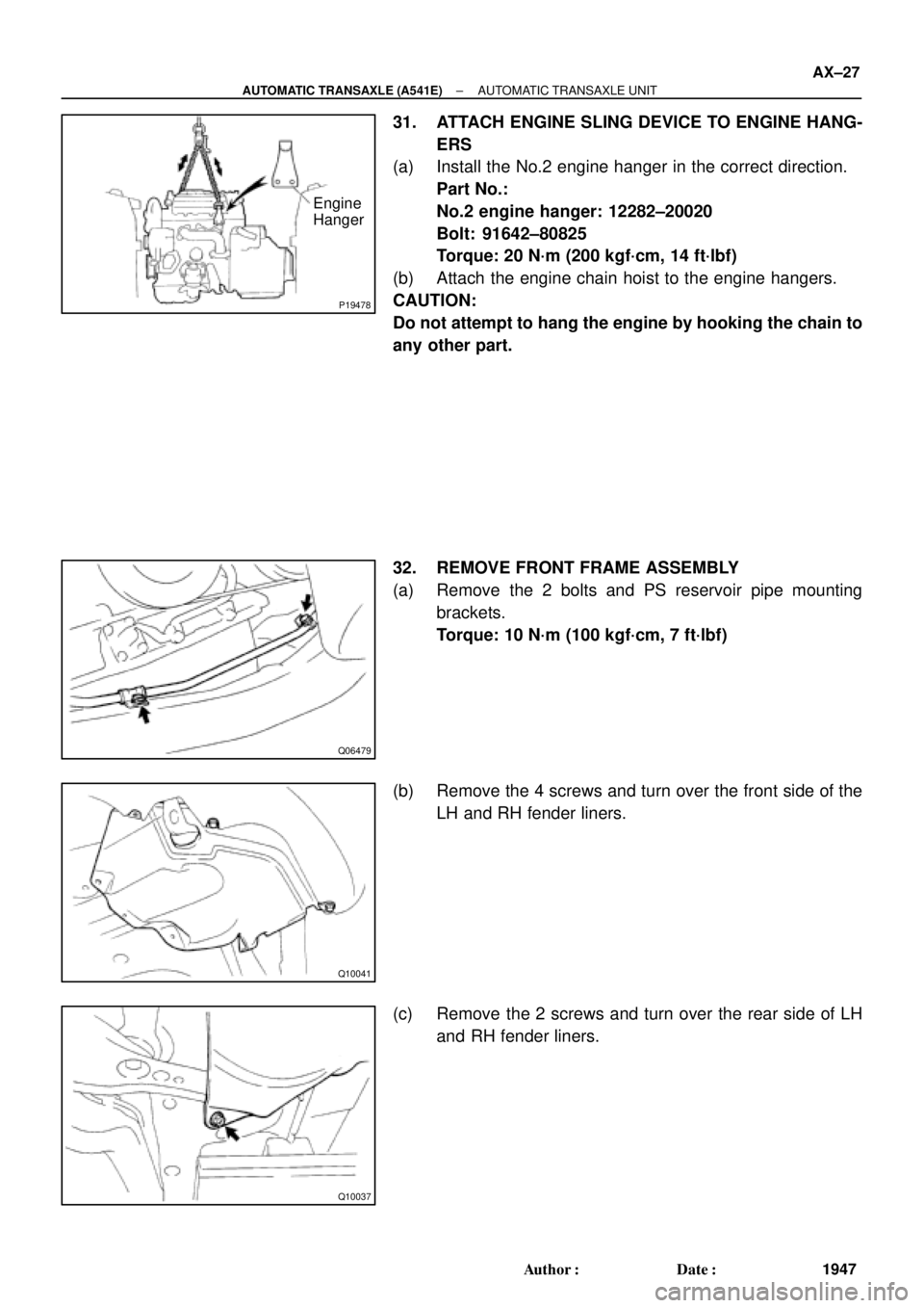
31. ATTACH ENGINE SLING DEVICE TO ENGINE HANG-
ERS
(a) Install the No.2 engine hanger in the correct direction.
Part No.:
No.2 engine hanger: 12282±20020
Bolt: 91642±80825
Torque: 20 N´m (200 kgf´cm, 14 ft´lbf)
(b) Attach the engine chain hoist to the engine hangers.
CAUTION:
Do not attempt to hang the engine by hooking the chain to
any other part.
32. REMOVE FRONT FRAME ASSEMBLY
(a) Remove the 2 bolts and PS reservoir pipe mounting
brackets.
Torque: 10 N´m (100 kgf´cm, 7 ft´lbf)
(b) Remove the 4 screws and turn over the front side of the
LH and RH fender liners.
(c) Remove the 2 screws and turn over the rear side of LH
and RH fender liners.
Page 1956 of 4770
AUTOMATIC TRANSAXLE UNIT
1948 Author�: Date�:
(d) Remove the 6 bolts and 4 nuts.
Torque:
19 mm head bo")
Q10172
Front
Q10064
Rear
Q04660
Q10036
Z14284
Left and lower AX±28
± AUTOMATIC TRANSAXLE (A541E)AUTOMATIC TRANSAXLE UNIT
1948 Author�: Date�:
(d) Remove the 6 bolts and 4 nuts.
Torque:
19 mm head bolt: 181 N´m (1,850 kgf´cm, 134 ft´lbf)
14 mm head bolt: 32 N´m (330 kgf´cm, 24 ft´lbf)
Nut: 36 N´m (370 kgf´cm, 27 ft´lbf)
(e) Remove the front frame assembly.
33. SUPPORT TRANSAXLE WITH A TRANSMISSION
JACK
34. REMOVE TORQUE CONVERTER CLUTCH MOUNT-
ING BOLTS
Turn the crankshaft to gain access to each bolt, remove the 6
bolts with holding the crankshaft pulley bolt by a wrench.
Torque: 41 N´m (420 kgf´cm, 30 ft´lbf)
HINT:
At the time of installation, please refer to the following item.
First install black colored bolt and then the 5 other bolts.
35. REMOVE EXHAUST MANIFOLD PLATE
(a) Remove the bolt, nut and exhaust manifold plate.
Torque:
Except California: 20 N´m (200 kgf´cm, 15 ft´lbf)
California: 34 N´m (350 kgf´cm, 25 ft´lbf)
36. REMOVE 3 LOWER TRANSAXLE±TO±ENGINE
BOLTS
Torque: 46 N´m (470 kgf´cm, 34 ft´lbf)
37. REMOVE TRANSAXLE ASSEMBLY
Separate the transaxle and engine, and lower the transaxle.
Page 1963 of 4770
BO0KV±01
H01708
Turn Signal Light Assembly
Upper Reinforcement
Sub±AssemblyTurn Signal Light Assembly
Fender Liner Front Bumper
Reinforcement
Energy Absorber
Mounting Plate
Front Bumper
Energy Absorber
Engine Under Cover Bumper Cover Emblem,
Radiator GrillFender Liner
N´m (kgf´cm, ft´lbf) : Specified torque
5.5 (55, 49 in.´lbf)34 (350, 25)
Clip
34 (350, 25)
No.2
Reinforcement
Clip BO±4
± BODYFRONT BUMPER
2352 Author�: Date�:
FRONT BUMPER
COMPONENTS
Page 2245 of 4770
 1MZ±FE engine:
Install a pad wear indicator plate on the inner pad.
(b) Apply disc brake grease to both sides of the inner anti±")
R00595
R02981
± BRAKEFRONT BRAKE PAD
BR±23
2046 Author�: Date�:
(a) 1MZ±FE engine:
Install a pad wear indicator plate on the inner pad.
(b) Apply disc brake grease to both sides of the inner anti±
squeal shims (See page BR±21).
(c) Install the 2 anti±squeal shims on each pad.
(d) Install inner pad with the pad wear indicator plate facing
upward.
(e) Install inner pad.
(f) Install outer pad.
NOTICE:
There should be no oil or grease adhering to the friction
surfaces of the pads or the disc.
(g) 5S±FE engine:
Install the 2 anti±squeal springs.
13. INSTALL CALIPER
(a) Draw out a small amount of brake fluid from the reservoir.
(b) Press in the piston with a hammer handle or similar imple-
ment.
HINT:
If the piston is difficult to push in, loosen the bleeder plug and
push in the piston while letting some brake fluid escape.
(c) Install the caliper.
(d) 5S±FE engine:
Hold the sliding pin and torque the installation bolt.
(e) 1MZ±FE engine:
Install the installation bolt.
Torque: 34 N´m (350 kgf´cm, 25 ft´lbf)
(f) Install the flexible hose and bolt to the bracket.
Torque: 29 N´m (300 kgf´cm, 21 ft´lbf)
14. INSTALL FRONT WHEEL
Torque: 103 N´m (1,050 kgf´cm, 76 ft´lbf)
15. DEPRESS BRAKE PEDAL SEVERAL TIMES
16. CHECK THAT FLUID LEVEL IS AT MAX LINE