2000 DODGE NEON electrical
[x] Cancel search: electricalPage 356 of 1285
ELECTRICALLY HEATED SYSTEMS
TABLE OF CONTENTS
page page
DESCRIPTION AND OPERATION
REAR WINDOW DEFOGGER SYSTEM.........1
REAR WINDOW DEFOGGER SWITCH.........1
DIAGNOSIS AND TESTING
GRID LINES.............................2
REAR WINDOW DEFOGGER SWITCH.........2REAR WINDOW DEFOGGER SYSTEM.........2
SERVICE PROCEDURES
GRID LINE AND TERMINAL REPAIR..........3
REMOVAL AND INSTALLATION
REAR WINDOW DEFOGGER SWITCH.........4
DESCRIPTION AND OPERATION
REAR WINDOW DEFOGGER SYSTEM
For proper operation of the Rear Window Defogger
system refer to the Owner's Manual.
The system consists of a rear glass with two verti-
cal bus bars and a series of electrically connected
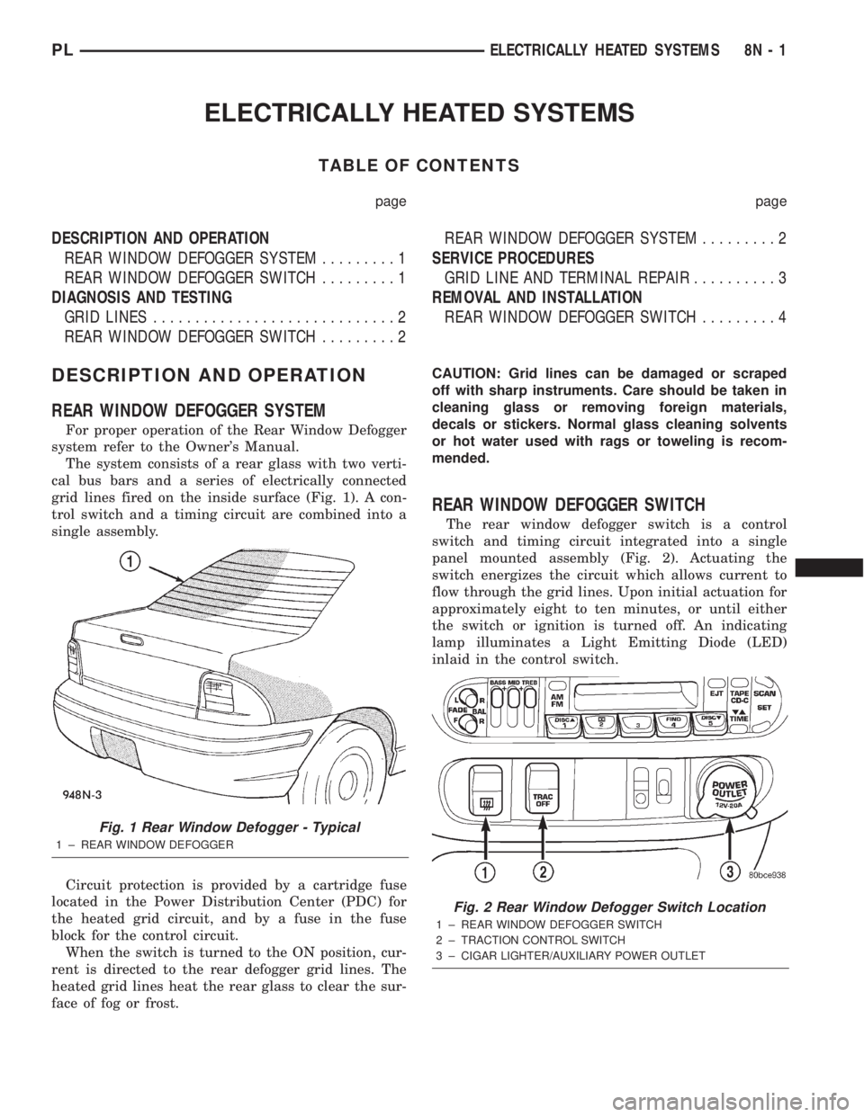
grid lines fired on the inside surface (Fig. 1). A con-
trol switch and a timing circuit are combined into a
single assembly.
Circuit protection is provided by a cartridge fuse
located in the Power Distribution Center (PDC) for
the heated grid circuit, and by a fuse in the fuse
block for the control circuit.
When the switch is turned to the ON position, cur-
rent is directed to the rear defogger grid lines. The
heated grid lines heat the rear glass to clear the sur-
face of fog or frost.CAUTION: Grid lines can be damaged or scraped
off with sharp instruments. Care should be taken in
cleaning glass or removing foreign materials,
decals or stickers. Normal glass cleaning solvents
or hot water used with rags or toweling is recom-
mended.
REAR WINDOW DEFOGGER SWITCH
The rear window defogger switch is a control
switch and timing circuit integrated into a single
panel mounted assembly (Fig. 2). Actuating the
switch energizes the circuit which allows current to
flow through the grid lines. Upon initial actuation for
approximately eight to ten minutes, or until either
the switch or ignition is turned off. An indicating
lamp illuminates a Light Emitting Diode (LED)
inlaid in the control switch.
Fig. 1 Rear Window Defogger - Typical
1 ± REAR WINDOW DEFOGGER
Fig. 2 Rear Window Defogger Switch Location
1 ± REAR WINDOW DEFOGGER SWITCH
2 ± TRACTION CONTROL SWITCH
3 ± CIGAR LIGHTER/AUXILIARY POWER OUTLET
PLELECTRICALLY HEATED SYSTEMS 8N - 1
Page 357 of 1285
DIAGNOSIS AND TESTING
GRID LINES
The horizontal grid lines and vertical bus bar lines
printed and fired on the inside surface of rear win-
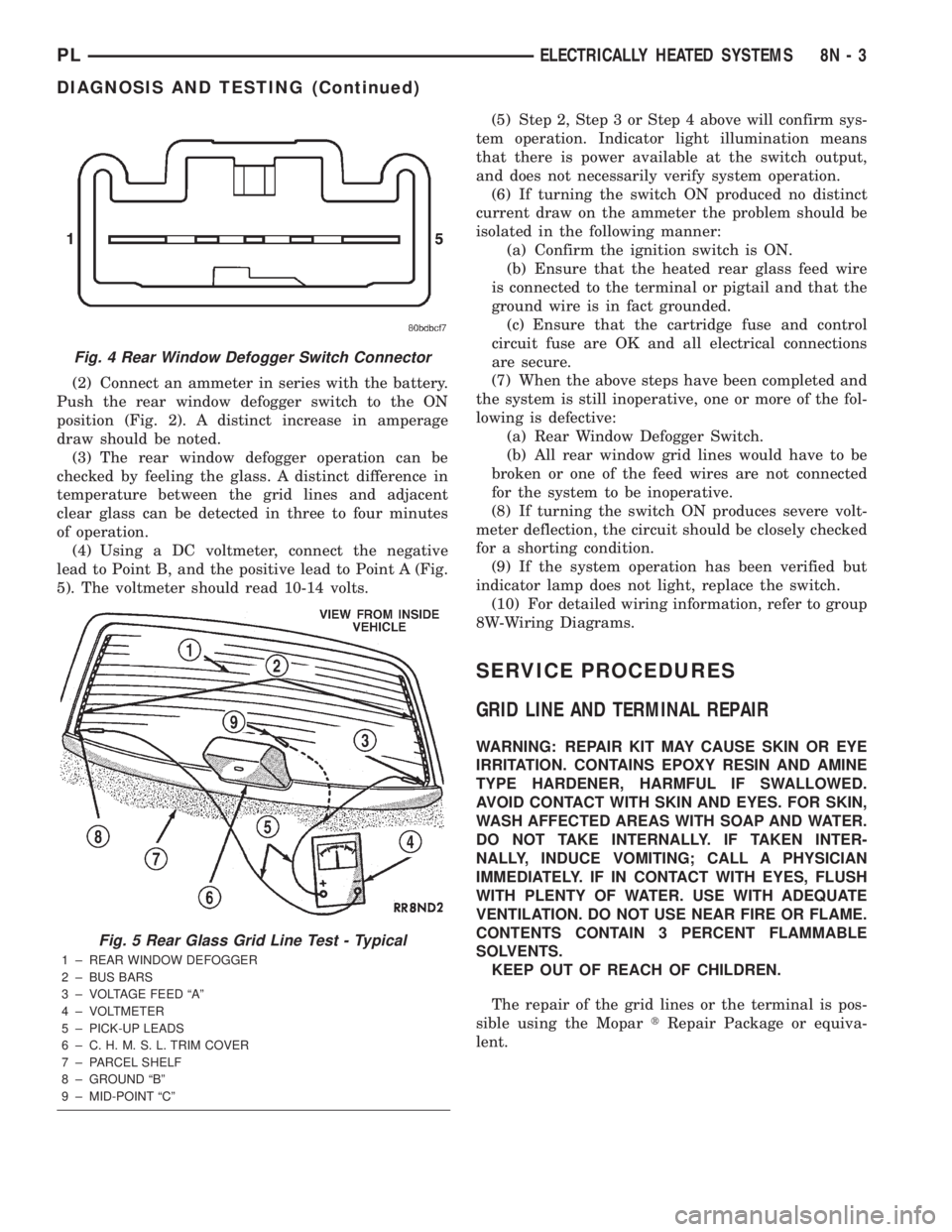
dow glass (Fig. 5) comprise an electrical parallel cir-
cuit. The electrically conductive lines are composed of
a silver-ceramic material which when fired on glass
becomes bonded to the glass and is highly resistant
to abrasion. It is possible however, that a break may
occur in an individual grid line resulting in no cur-
rent flow through the line. To detect breaks in grid
lines the following procedure is required:
(1) Turn ignition ON and turn control switch to
ON. The LED should come on.
(2) Using a DC voltmeter with 0-15 volt range,
contact terminal (B) with the negative lead of the
voltmeter. With the positive lead of the voltmeter,
contact terminal (A) (Fig. 5). The voltmeter should
read 10-14 volts. A lower voltage reading indicates a
poor connection in the feed or the ground circuit.
(3) With the negative lead of the voltmeter, contact
a good body ground point. The voltage reading should
not change.
(4) Connect the negative lead of the voltmeter to
terminal (B) and touch each grid line at Mid-Point
with the positive lead. A reading of:
²Approximately 6 volts indicates the line is OK.
²0 volts indicates a break in line between Mid-
Point (C) and terminal (A).
²10-14 volts indicates a break between Mid-Point
(C) and terminal (B).
Move the lead toward the break and voltage will
change as soon as the break is crossed. Refer to (Fig.
5).
REAR WINDOW DEFOGGER SWITCH
The rear window defogger switch may be tested in
the vehicle or out of the vehicle, on the bench.
IN-VEHICLE TESTING
(1) Remove the switch from the instrument panel
but leave the switch connected, refer to Group 8E-In-
strument Panel and Systems, Auxiliary Switch Bezel
Removal and Installation.
(2) Turn the ignition switch ON.
(3) Using a voltmeter, check for battery voltage at
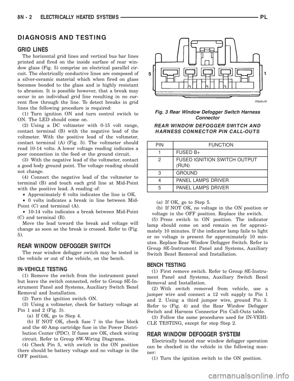
Pin 1 and 2 (Fig. 3).
(a) If OK, go to Step 4.
(b) If NOT OK, check fuse 7 in the fuse block
and the 40 Amp cartridge fuse in the Power Distri-
bution Center (PDC). If fuses are OK, check wiring
circuit. Refer to Group 8W-Wiring Diagrams.
(4) Check Pin 5, with switch in the ON position
there should be battery voltage and no voltage in the
OFF position.(a) If OK, go to Step 5.
(b) If NOT OK, no voltage in the ON position or
voltage in the OFF position. Replace the switch.
(5) Press switch to ON position. The indicator
lamp should come on and remain on for approxi-
mately 10 minutes. If the indicator lamp fails to light
or no voltage is present for approximately 10 min-
utes. Replace Rear Window Defogger Switch. Refer to
Group 8E-Instrument Panel and Systems, Auxiliary
Switch Bezel Removal and Installation.
BENCH TESTING
(1) First remove switch. Refer to Group 8E-Instru-
ment Panel and Systems, Auxiliary Switch Bezel
Removal and Installation.
(2) With switch removed from vehicle, use a
jumper wire and connect a 12 volt supply to Pin 1
and 2. Using a third jumper wire, ground Pin 3.
Refer to (Fig. 4) and the Rear Window Defogger
Switch and Harness Connector Pin Call-Outs table.
(3) Follow the same procedures used for IN-VEHI-
CLE TESTING, except for step Step 2.
REAR WINDOW DEFOGGER SYSTEM
Electrically heated rear window defogger operation
can be checked in the vehicle in the following man-
ner:
(1) Turn the ignition switch to the ON position.
Fig. 3 Rear Window Defogger Switch Harness
Connector
REAR WINDOW DEFOGGER SWITCH AND
HARNESS CONNECTOR PIN CALL-OUTS
PIN FUNCTION
1 FUSED B+
2 FUSED IGNITION SWITCH OUTPUT
(RUN)
3 GROUND
4 PANEL LAMPS DRIVER
5 PANEL LAMPS DRIVER
8N - 2 ELECTRICALLY HEATED SYSTEMSPL
Page 358 of 1285
(2) Connect an ammeter in series with the battery.
Push the rear window defogger switch to the ON
position (Fig. 2). A distinct increase in amperage
draw should be noted.
(3) The rear window defogger operation can be
checked by feeling the glass. A distinct difference in
temperature between the grid lines and adjacent
clear glass can be detected in three to four minutes
of operation.
(4) Using a DC voltmeter, connect the negative
lead to Point B, and the positive lead to Point A (Fig.
5). The voltmeter should read 10-14 volts.(5) Step 2, Step 3 or Step 4 above will confirm sys-
tem operation. Indicator light illumination means
that there is power available at the switch output,
and does not necessarily verify system operation.
(6) If turning the switch ON produced no distinct
current draw on the ammeter the problem should be
isolated in the following manner:
(a) Confirm the ignition switch is ON.
(b) Ensure that the heated rear glass feed wire
is connected to the terminal or pigtail and that the
ground wire is in fact grounded.
(c) Ensure that the cartridge fuse and control
circuit fuse are OK and all electrical connections
are secure.
(7) When the above steps have been completed and
the system is still inoperative, one or more of the fol-
lowing is defective:
(a) Rear Window Defogger Switch.
(b) All rear window grid lines would have to be
broken or one of the feed wires are not connected
for the system to be inoperative.
(8) If turning the switch ON produces severe volt-
meter deflection, the circuit should be closely checked
for a shorting condition.
(9) If the system operation has been verified but
indicator lamp does not light, replace the switch.
(10) For detailed wiring information, refer to group
8W-Wiring Diagrams.
SERVICE PROCEDURES
GRID LINE AND TERMINAL REPAIR
WARNING: REPAIR KIT MAY CAUSE SKIN OR EYE
IRRITATION. CONTAINS EPOXY RESIN AND AMINE
TYPE HARDENER, HARMFUL IF SWALLOWED.
AVOID CONTACT WITH SKIN AND EYES. FOR SKIN,
WASH AFFECTED AREAS WITH SOAP AND WATER.
DO NOT TAKE INTERNALLY. IF TAKEN INTER-
NALLY, INDUCE VOMITING; CALL A PHYSICIAN
IMMEDIATELY. IF IN CONTACT WITH EYES, FLUSH
WITH PLENTY OF WATER. USE WITH ADEQUATE
VENTILATION. DO NOT USE NEAR FIRE OR FLAME.
CONTENTS CONTAIN 3 PERCENT FLAMMABLE
SOLVENTS.
KEEP OUT OF REACH OF CHILDREN.
The repair of the grid lines or the terminal is pos-
sible using the MopartRepair Package or equiva-
lent.
Fig. 4 Rear Window Defogger Switch Connector
Fig. 5 Rear Glass Grid Line Test - Typical
1 ± REAR WINDOW DEFOGGER
2 ± BUS BARS
3 ± VOLTAGE FEED ªAº
4 ± VOLTMETER
5 ± PICK-UP LEADS
6 ± C. H. M. S. L. TRIM COVER
7 ± PARCEL SHELF
8 ± GROUND ªBº
9 ± MID-POINT ªCº
PLELECTRICALLY HEATED SYSTEMS 8N - 3
DIAGNOSIS AND TESTING (Continued)
Page 359 of 1285
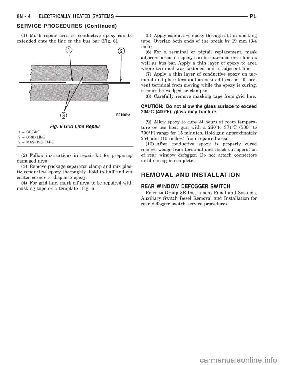
(1) Mask repair area so conductive epoxy can be
extended onto the line or the bus bar (Fig. 6).
(2) Follow instructions in repair kit for preparing
damaged area.
(3) Remove package separator clamp and mix plas-
tic conductive epoxy thoroughly. Fold in half and cut
center corner to dispense epoxy.
(4) For grid line, mark off area to be repaired with
masking tape or a template (Fig. 6).(5) Apply conductive epoxy through slit in masking
tape. Overlap both ends of the break by 19 mm (3/4
inch).
(6) For a terminal or pigtail replacement, mask
adjacent areas so epoxy can be extended onto line as
well as bus bar. Apply a thin layer of epoxy to area
where terminal was fastened and to adjacent line.
(7) Apply a thin layer of conductive epoxy on ter-
minal and place terminal on desired location. To pre-
vent terminal from moving while the epoxy is curing,
it must be wedged or clamped.
(8) Carefully remove masking tape from grid line.
CAUTION: Do not allow the glass surface to exceed
204ÉC (400ÉF), glass may fracture.
(9) Allow epoxy to cure 24 hours at room tempera-
ture or use heat gun with a 260Éto 371ÉC (500É to
700ÉF) range for 15 minutes. Hold gun approximately
254 mm (10 inches) from repaired area.
(10) After conductive epoxy is properly cured
remove wedge from terminal and check out operation
of rear window defogger. Do not attach connectors
until curing is complete.
REMOVAL AND INSTALLATION
REAR WINDOW DEFOGGER SWITCH
Refer to Group 8E-Instrument Panel and Systems,
Auxiliary Switch Bezel Removal and Installation for
rear defogger switch service procedures.
Fig. 6 Grid Line Repair
1 ± BREAK
2 ± GRID LINE
3 ± MASKING TAPE
8N - 4 ELECTRICALLY HEATED SYSTEMSPL
SERVICE PROCEDURES (Continued)
Page 360 of 1285
POWER DISTRIBUTION SYSTEMS
TABLE OF CONTENTS
page page
DESCRIPTION AND OPERATION
POWER DISTRIBUTION SYSTEM.............1
POWER DISTRIBUTION CENTER (PDC).......1
FUSE BLOCK.............................2REMOVAL AND INSTALLATION
FUSE BLOCK.............................2
POWER DISTRIBUTION CENTER (PDC).......2
DESCRIPTION AND OPERATION
POWER DISTRIBUTION SYSTEM
This group covers the various standard and
optional power distribution components used on this
model. Refer to the Component Index of Group 8W -
Wiring Diagrams for complete circuit diagrams of the
various power distribution components.
The power distribution system for this vehicle is
designed to provide safe, reliable, centralized and
convenient to access distribution of the electrical cur-
rent required to operate all of the many standard
and optional factory-installed electrical and electronic
powertrain, chassis, safety, comfort and convenience
systems. At the same time, these systems were
designed to provide centralized locations for conduct-
ing diagnosis of faulty circuits, and for sourcing the
additional current requirements of many aftermarket
vehicle accessory and convenience items.
These power distribution systems also incorporate
various types of circuit control and protection fea-
tures, including:
²Fuses
²Fuse cartridges
²Fusible links
²Automatic resetting circuit breakers
²Relays
²Flashers
²Timers
²Circuit splice blocks.
The power distribution system for this vehicle con-
sists of the following components:
²Power Distribution Center (PDC)
²Fuse Block
Following are general descriptions of the major
components in the power distribution system. Refer
to the owner's manual in the vehicle glove box for
more information on the features, use and operation
of all of the power distribution system components.
POWER DISTRIBUTION CENTER (PDC)
All of the electrical current distributed throughout
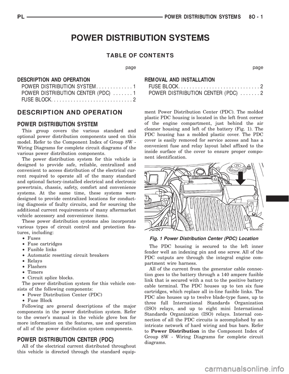
this vehicle is directed through the standard equip-ment Power Distribution Center (PDC). The molded
plastic PDC housing is located in the left front corner
of the engine compartment, just behind the air
cleaner housing and left of the battery (Fig. 1). The
PDC housing has a molded plastic cover. The PDC
cover is easily removed for service access and has a
convenient fuse and relay layout label affixed to the
inside surface of the cover to ensure proper compo-
nent identification.
The PDC housing is secured to the left inner
fender well an indexing pin and one screw. All of the
PDC outputs are through the integral engine com-
partment wire harness.
All of the current from the generator cable connec-
tion goes to the battery through a 140 ampere fusible
link that is secured with a nut to the positive battery
cable terminal. The PDC houses up to ten six fuse
cartridges, which replace all in-line fusible links. The
PDC also houses up to twelve blade-type fuses, up to
three full International Standards Organization
(ISO) relays, and up to eight mini International
Standards Organization (ISO) relays. Internal con-
nection of all the PDC circuits is accomplished by an
intricate network of hard wiring and bus bars. Refer
toPower Distributionin the Component Index of
Group 8W - Wiring Diagrams for complete circuit
diagrams.
Fig. 1 Power Distribution Center (PDC) Location
PLPOWER DISTRIBUTION SYSTEMS 8O - 1
Page 361 of 1285
The fusible link, fuses and relays are available for
service replacement. The PDC unit cannot be
repaired and is only serviced as a unit with the
engine compartment wire harness. If the PDC is
faulty or damaged, the engine compartment wire har-
ness assembly must be replaced.
FUSE BLOCK
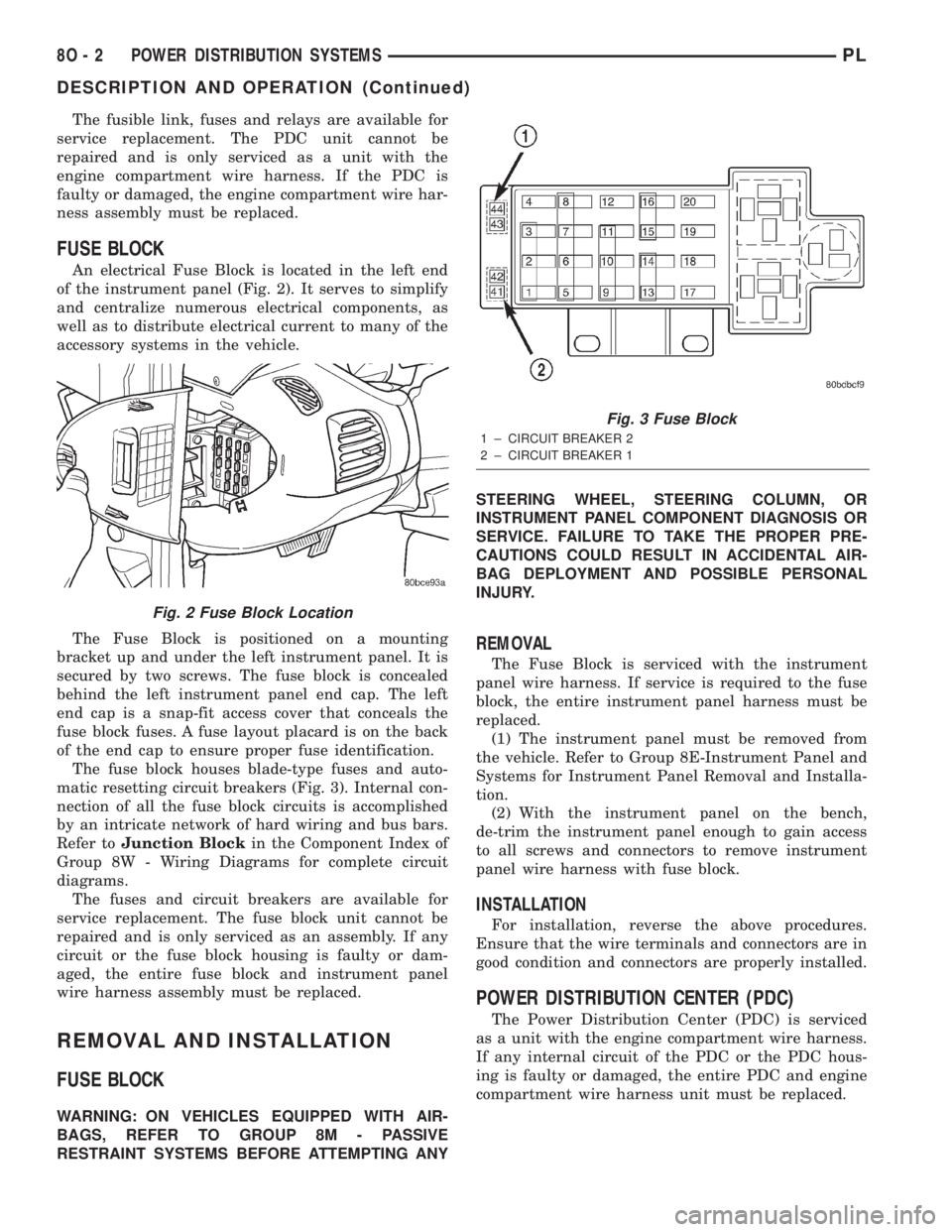
An electrical Fuse Block is located in the left end
of the instrument panel (Fig. 2). It serves to simplify
and centralize numerous electrical components, as
well as to distribute electrical current to many of the
accessory systems in the vehicle.
The Fuse Block is positioned on a mounting
bracket up and under the left instrument panel. It is
secured by two screws. The fuse block is concealed
behind the left instrument panel end cap. The left
end cap is a snap-fit access cover that conceals the
fuse block fuses. A fuse layout placard is on the back
of the end cap to ensure proper fuse identification.
The fuse block houses blade-type fuses and auto-
matic resetting circuit breakers (Fig. 3). Internal con-
nection of all the fuse block circuits is accomplished
by an intricate network of hard wiring and bus bars.
Refer toJunction Blockin the Component Index of
Group 8W - Wiring Diagrams for complete circuit
diagrams.
The fuses and circuit breakers are available for
service replacement. The fuse block unit cannot be
repaired and is only serviced as an assembly. If any
circuit or the fuse block housing is faulty or dam-
aged, the entire fuse block and instrument panel
wire harness assembly must be replaced.
REMOVAL AND INSTALLATION
FUSE BLOCK
WARNING: ON VEHICLES EQUIPPED WITH AIR-
BAGS, REFER TO GROUP 8M - PASSIVE
RESTRAINT SYSTEMS BEFORE ATTEMPTING ANYSTEERING WHEEL, STEERING COLUMN, OR
INSTRUMENT PANEL COMPONENT DIAGNOSIS OR
SERVICE. FAILURE TO TAKE THE PROPER PRE-
CAUTIONS COULD RESULT IN ACCIDENTAL AIR-
BAG DEPLOYMENT AND POSSIBLE PERSONAL
INJURY.
REMOVAL
The Fuse Block is serviced with the instrument
panel wire harness. If service is required to the fuse
block, the entire instrument panel harness must be
replaced.
(1) The instrument panel must be removed from
the vehicle. Refer to Group 8E-Instrument Panel and
Systems for Instrument Panel Removal and Installa-
tion.
(2) With the instrument panel on the bench,
de-trim the instrument panel enough to gain access
to all screws and connectors to remove instrument
panel wire harness with fuse block.
INSTALLATION
For installation, reverse the above procedures.
Ensure that the wire terminals and connectors are in
good condition and connectors are properly installed.
POWER DISTRIBUTION CENTER (PDC)
The Power Distribution Center (PDC) is serviced
as a unit with the engine compartment wire harness.
If any internal circuit of the PDC or the PDC hous-
ing is faulty or damaged, the entire PDC and engine
compartment wire harness unit must be replaced.
Fig. 2 Fuse Block Location
Fig. 3 Fuse Block
1 ± CIRCUIT BREAKER 2
2 ± CIRCUIT BREAKER 1
8O - 2 POWER DISTRIBUTION SYSTEMSPL
DESCRIPTION AND OPERATION (Continued)
Page 364 of 1285
POWER LOCK SYSTEMS
TABLE OF CONTENTS
page page
POWER DOOR LOCKS...................... 1REMOTE KEYLESS ENTRY (RKE).............. 4
POWER DOOR LOCKS
TABLE OF CONTENTS
page page
DESCRIPTION AND OPERATION
INTRODUCTION..........................1
POWER DOOR LOCKS.....................2
CHILD PROTECTION LOCKS................2
DOOR LOCK INHIBIT.......................2
DIAGNOSIS AND TESTING
DOOR LOCK MOTOR......................2
DOOR LOCK SWITCH......................2SERVICE PROCEDURES
DOUBLE ACTIVATION UNLOCK...............3
ROLLING DOOR LOCKS....................3
REMOVAL AND INSTALLATION
DOOR LOCK MOTOR/LATCH.................3
DOOR LOCK SWITCH......................3
REMOTE KEYLESS ENTRY (RKE) MODULE.....3
DESCRIPTION AND OPERATION
INTRODUCTION
All doors can be locked or unlocked electrically by
operating the switch on either front door panel.
When the door lock switch is activated the Remote
Keyless Entry Module provides power to the door
lock motors through relays internal to the module.
The Remote Keyless Entry (RKE) Module also con-
trols the Vehicle Theft Security System (VTSS).
All doors can be locked or unlocked mechanically
and independently with their respective locking
knobs. The front doors can also be unlocked by actu-
ation of the inside remote door handle.
The RKE Module has three modes of operation
including customer usage mode, dealer lot storage
mode, and shipping mode. The customer usage mode
provides full functionality of the module and is the
mode in which the RKE module should be operating
when used by the customer. Dealer lot storage mode
and shipping modes are reduced power modes meant
to extend vehicle battery life during shipping and
storage in the dealer lot. Dealer lot storage mode pro-
vides limited VTSS and power door lock functions,
but disables the Remote Keyless Entry (RKE) func-
tions. This mode is intended to be used when the
vehicle is on the dealer lot to provide VTSS coverageof the vehicle while minimizing battery drain. Ship-
ping mode disables all normal functions (i.e. power
door locks, RKE, and VTSS) of the module, and is
intended to be used when the vehicle is shipped from
the assembly plant.
NOTE: The dealer must remove the module from
ªShip Modeº and place the RKE Module into either
the ªDealer Lotº storage or ªCustomer Usageº
modes of operation after receiving the vehicle from
the assembly plant. Refer to Group 8Q-Vehicle
Theft/Security Systems, Switching Operating
Modes/Configuring a New Module under Service
Procedures.
CENTRAL LOCKING/UNLOCKING
The door locks can be locked or unlocked electri-
cally via the exterior door key cylinders to provide
the central locking/unlocking feature. The central
locking/unlocking feature incorporates a customer
programmable ``Double activation unlockº feature
which operates in the following manner: When
enabled, the first turn of the key cylinder to the
UNLOCK position (toward the front of the vehicle)
will mechanically unlock the door whose key cylinder
is being turned. A second turn of the key cylinder to
the UNLOCK position (within five seconds of the
PLPOWER LOCK SYSTEMS 8P - 1
Page 365 of 1285
first turn) will cause all vehicle doors to unlock elec-
trically. When this feature is disabled, all vehicle
doors will be unlocked electrically upon the first turn
of a key cylinder to the UNLOCK position. The vehi-
cle is locked electrically by turning the key cylinder
to the LOCK position once, regardless of the state of
the double activation unlock feature.
POWER DOOR LOCKS
The Remote Keyless Entry (RKE) Module actuates
the power door lock relays when a door lock switch is
activated. If the door lock switch is pressed for longer
than eight consecutive seconds, the RKE module will
de-energize the door lock motors.
The system includes the rolling door locking fea-
ture. The vehicle is shipped with the system enabled.
When the system is disabled the door locks will work
by use of the door lock switches and the Remote Key-
less Entry system only. When the rolling door lock
system is enabled, the RKE module will automati-
cally lock all the vehicle doors when all of the follow-
ing conditions are met:
²All doors are closed
²The vehicle speed exceeds 15 +/- 1 mph.
²The throttle position sensor tip-in is greater
than 10 +/- 2 degrees.
The RKE module will automatically re-lock all
doors if the above conditions are met and if any of
the doors become ajar and then closed again.
The enabling/disabling of the rolling door lock fea-
ture is customer programmable, as well as program-
mable with the DRB IIItscan tool.
The power lock motors are also equipped with a
thermal protection system which prevents the motors
from burning out. The motors may chatter if they are
continuously activated.
CHILD PROTECTION LOCKS
The child protection locks are on the rear doors
only. The lock, when engaged, will disable the inside
door handle from opening the door. The lock is part
of the latch/lock assembly. The lock is engaged by
moving a lever that is located on the rearward inside
edge of the door.
DOOR LOCK INHIBIT
With the key in the ignition switch and the driver
door open, the Remote Keyless Entry (RKE) Modulewill ignore the command to lock the power door locks
via the interior driver door lock switch. Once the key
is removed, or the driver door is closed, the RKE
module will allow the power door locks to lock via the
interior door lock switches.
DIAGNOSIS AND TESTING
DOOR LOCK MOTOR
(1) Make certain battery is in normal condition
and fuses powering the RKE module aren't blown
before circuits are tested.
(2) To determine which motor is faulty, check each
individual door for electrical lock and unlock or dis-
connect the motor connectors one at a time, while
operating the door lock switch.
(3) In the event that none of the motors work, the
problem maybe caused by a shorted motor, a bad
switch or a bad relay internal to the RKE module.
Disconnecting a defective motor will allow the others
to work.
(4) To test an individual door lock motor, discon-
nect the electrical connector from the motor.
(5) To lock the door, connect a 12 volt power source
to one pin of the lock motor and a ground wire to the
other pin.
(6) To unlock the door, reverse the wire connec-
tions at the motor pin terminals.
(7) If these results are NOT obtained, replace the
motor.
DOOR LOCK SWITCH
(1) Remove the switch from its mounting location,
and disconnect from vehicle wiring harness. Refer to
Door Lock Switch Removal and Installation in this
section.
(2) Using an ohmmeter, refer to Door Lock Switch
Resistance Test table to determine if switch resis-
tance is correct in the Lock and Unlock switch posi-
tions. Refer to Group 8W-Wiring Diagrams for
harness connector pin-outs.
DOOR LOCK SWITCH RESISTANCE
SWITCH POSITION CONTINUITY BETWEEN RESISTANCE VALUE
LOCK 2 AND 3 1000V
UNLOCK 2 AND 3 249V
8P - 2 POWER LOCK SYSTEMSPL
DESCRIPTION AND OPERATION (Continued)