2000 DODGE NEON electrical
[x] Cancel search: electricalPage 289 of 1285
INSTALLATION
(1) Install retaining clip to cable at servo.
(2) Install 2 nuts at cable to servo and servo
bracket, tighten to 7 N´m (60 ins. lbs.).
(3) Connect electrical connector to servo.
(4) Connect vacuum hose to servo
SPEED CONTROL SWITCH
The speed control switches are mounted in the
steering wheel and wired through the clock spring
device under the airbag module (Fig. 1).
WARNING: IF REMOVAL OF AIRBAG MODULE IS
NECESSARY, REFER TO THE RESTRAINT SYS-
TEMS.
REMOVAL
(1) Turn off ignition.
(2) Remove two screws from side of each switch.
(3) Rock switch away from airbag and steering
wheel.
(4) Disconnect two-way electrical connector.
(5) Repeat for the other switch.
INSTALLATION
(1) Install switches.
(2) Connect two-way electrical connector.
(3) Install two screws to the side of each switch.
(4) Install airbag, refer to the Restraint Systems
SPEED CONTROL SERVO CABLE
REMOVAL
(1) Disconnect the negative battery cable.
(2) Remove the throttle cable cover.
(3) Remove speed control cable from throttle lever
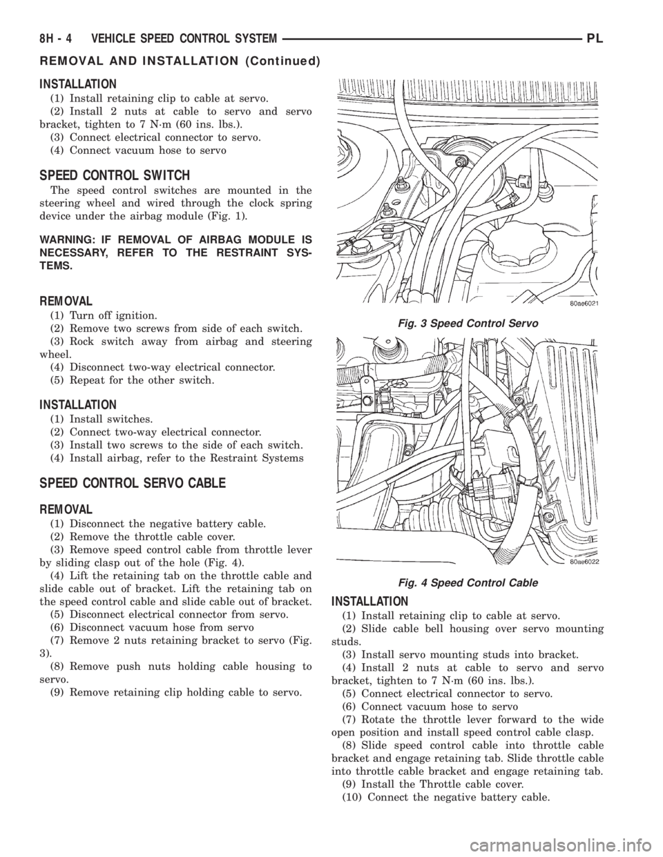
by sliding clasp out of the hole (Fig. 4).
(4) Lift the retaining tab on the throttle cable and
slide cable out of bracket. Lift the retaining tab on
the speed control cable and slide cable out of bracket.
(5) Disconnect electrical connector from servo.
(6) Disconnect vacuum hose from servo
(7) Remove 2 nuts retaining bracket to servo (Fig.
3).
(8) Remove push nuts holding cable housing to
servo.
(9) Remove retaining clip holding cable to servo.
INSTALLATION
(1) Install retaining clip to cable at servo.
(2) Slide cable bell housing over servo mounting
studs.
(3) Install servo mounting studs into bracket.
(4) Install 2 nuts at cable to servo and servo
bracket, tighten to 7 N´m (60 ins. lbs.).
(5) Connect electrical connector to servo.
(6) Connect vacuum hose to servo
(7) Rotate the throttle lever forward to the wide
open position and install speed control cable clasp.
(8) Slide speed control cable into throttle cable
bracket and engage retaining tab. Slide throttle cable
into throttle cable bracket and engage retaining tab.
(9) Install the Throttle cable cover.
(10) Connect the negative battery cable.
Fig. 3 Speed Control Servo
Fig. 4 Speed Control Cable
8H - 4 VEHICLE SPEED CONTROL SYSTEMPL
REMOVAL AND INSTALLATION (Continued)
Page 292 of 1285
TURN SIGNAL and HAZARD WARNING SYSTEMS
TABLE OF CONTENTS
page page
GENERAL INFORMATION
INTRODUCTION..........................1
DESCRIPTION AND OPERATION
HAZARD WARNING SYSTEM................2
HEADLAMP SWITCH......................2
COMBINATION FLASHER...................2DIAGNOSIS AND TESTING
MULTI-FUNCTION SWITCH.................3
REMOVAL AND INSTALLATION
COMBINATION FLASHER...................5
MULTI-FUNCTION SWITCH.................5
GENERAL INFORMATION
INTRODUCTION
WARNING: ON VEHICLES EQUIPPED WITH AIR-
BAG, SEE GROUP 8M, PASSIVE RESTRAINT SYS-
TEMS FOR AIRBAG REMOVAL.
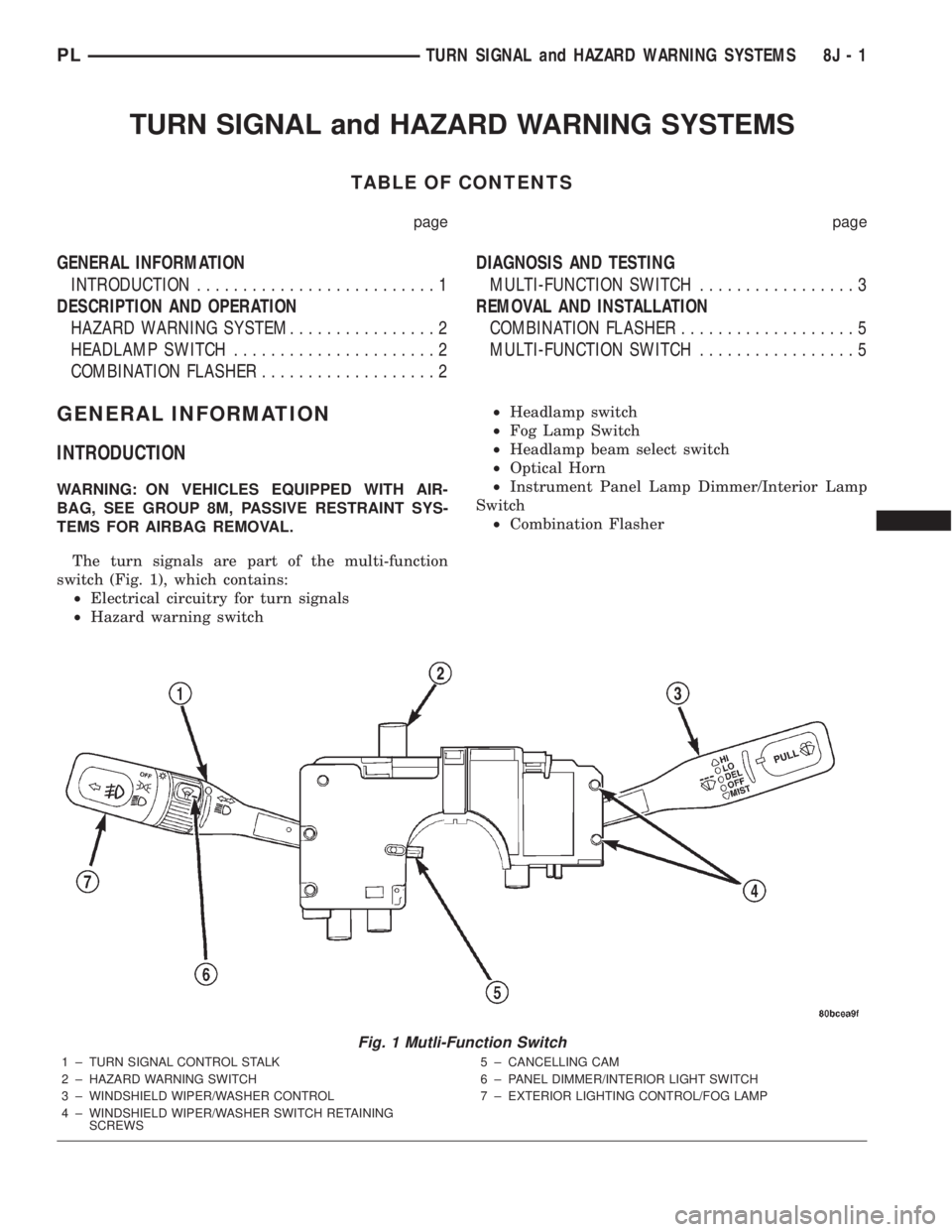
The turn signals are part of the multi-function
switch (Fig. 1), which contains:
²Electrical circuitry for turn signals
²Hazard warning switch²Headlamp switch
²Fog Lamp Switch
²Headlamp beam select switch
²Optical Horn
²Instrument Panel Lamp Dimmer/Interior Lamp
Switch
²Combination Flasher
Fig. 1 Mutli-Function Switch
1 ± TURN SIGNAL CONTROL STALK
2 ± HAZARD WARNING SWITCH
3 ± WINDSHIELD WIPER/WASHER CONTROL
4 ± WINDSHIELD WIPER/WASHER SWITCH RETAINING
SCREWS5 ± CANCELLING CAM
6 ± PANEL DIMMER/INTERIOR LIGHT SWITCH
7 ± EXTERIOR LIGHTING CONTROL/FOG LAMP
PLTURN SIGNAL and HAZARD WARNING SYSTEMS 8J - 1
Page 305 of 1285
WINDSHIELD WASHER SYSTEM
TABLE OF CONTENTS
page page
DESCRIPTION AND OPERATION
WINDSHIELD WASHER NOZZLE(S)............8
WINDSHIELD WASHER SYSTEM.............8
DIAGNOSIS AND TESTING
WINDSHIELD WASHER SYSTEM.............9REMOVAL AND INSTALLATION
WINDSHIELD WASHER HOSE................9
WINDSHIELD WASHER NOZZLES.............9
WINDSHIELD WASHER RESERVOIR..........10
WINDSHIELD WASHER PUMP...............10
DESCRIPTION AND OPERATION
WINDSHIELD WASHER NOZZLE(S)
This model is equipped with two hood mounted
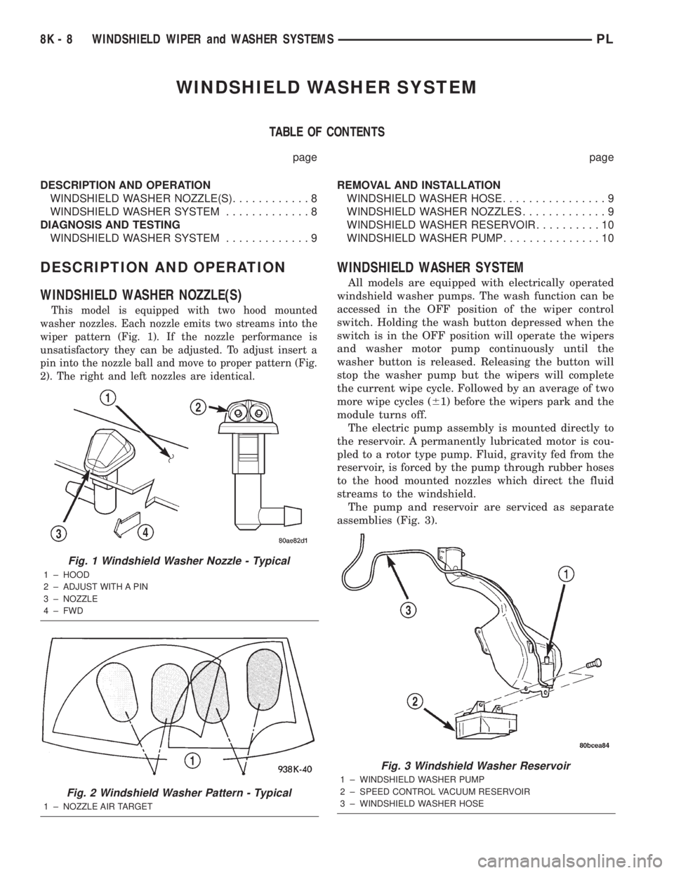
washer nozzles. Each nozzle emits two streams into the
wiper pattern (Fig. 1). If the nozzle performance is
unsatisfactory they can be adjusted. To adjust insert a
pin into the nozzle ball and move to proper pattern (Fig.
2). The right and left nozzles are identical.
WINDSHIELD WASHER SYSTEM
All models are equipped with electrically operated
windshield washer pumps. The wash function can be
accessed in the OFF position of the wiper control
switch. Holding the wash button depressed when the
switch is in the OFF position will operate the wipers
and washer motor pump continuously until the
washer button is released. Releasing the button will
stop the washer pump but the wipers will complete
the current wipe cycle. Followed by an average of two
more wipe cycles (61) before the wipers park and the
module turns off.
The electric pump assembly is mounted directly to
the reservoir. A permanently lubricated motor is cou-
pled to a rotor type pump. Fluid, gravity fed from the
reservoir, is forced by the pump through rubber hoses
to the hood mounted nozzles which direct the fluid
streams to the windshield.
The pump and reservoir are serviced as separate
assemblies (Fig. 3).
Fig. 1 Windshield Washer Nozzle - Typical
1 ± HOOD
2 ± ADJUST WITH A PIN
3 ± NOZZLE
4 ± FWD
Fig. 2 Windshield Washer Pattern - Typical
1 ± NOZZLE AIR TARGET
Fig. 3 Windshield Washer Reservoir
1 ± WINDSHIELD WASHER PUMP
2 ± SPEED CONTROL VACUUM RESERVOIR
3 ± WINDSHIELD WASHER HOSE
8K - 8 WINDSHIELD WIPER and WASHER SYSTEMSPL
Page 329 of 1285
LAMP BULB SERVICE
TABLE OF CONTENTS
page page
REMOVAL AND INSTALLATION
CENTER HIGH MOUNTED STOP LAMP BULB....4
FRONT TURN SIGNAL LAMP BULB............4
FRONT POSITION LAMP BULB...............5
FRONT FOG LAMP BULB...................6
HEADLAMP BULB.........................6REAR LICENSE PLATE LAMP BULBS..........7
REAR FOG LAMP BULB....................8
SIDE REPEATER LAMP BULB................9
TAIL, STOP, BACK-UP AND TURN SIGNAL
LAMP BULBS..........................10
REMOVAL AND INSTALLATION
CENTER HIGH MOUNTED STOP LAMP BULB
REMOVAL
(1) Open the trunklid.
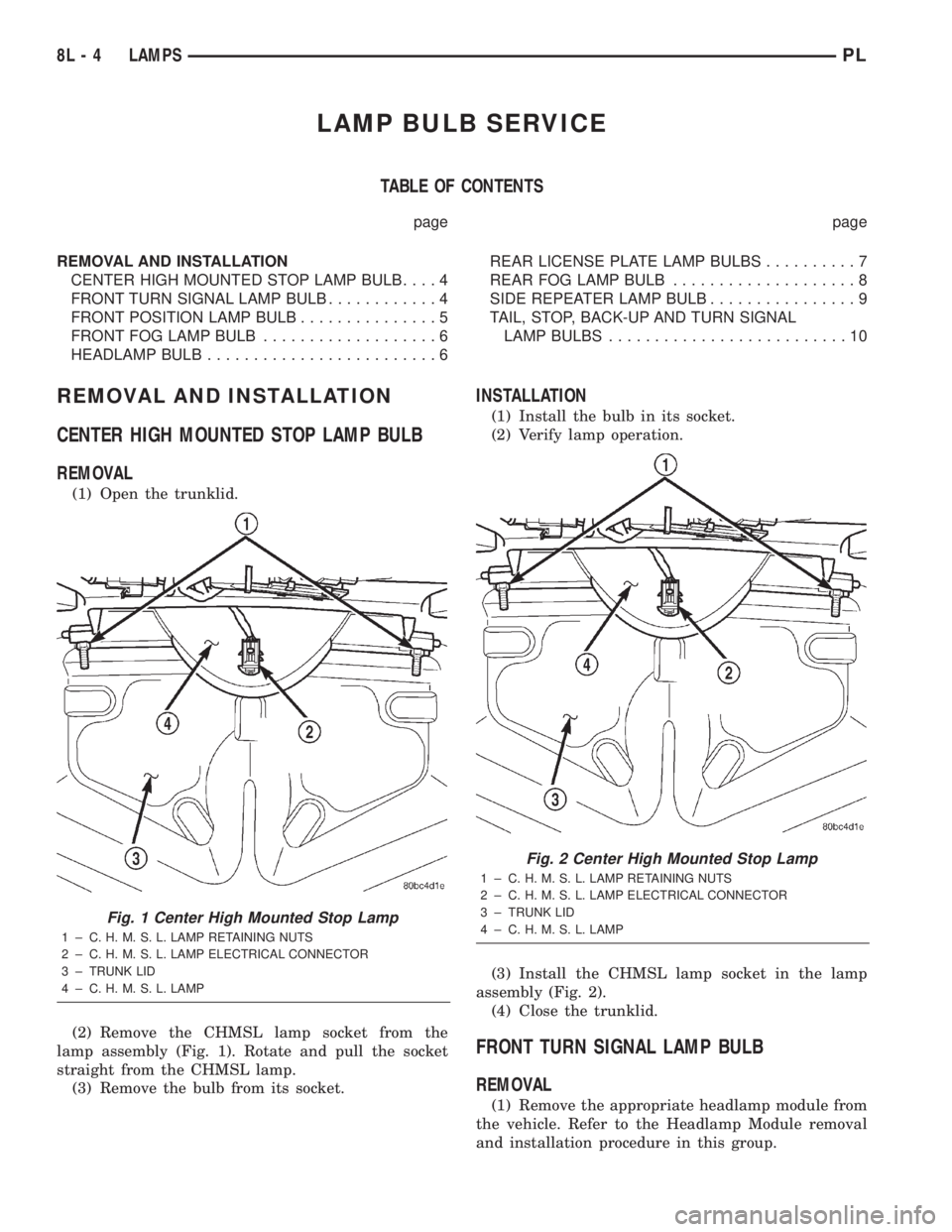
(2) Remove the CHMSL lamp socket from the
lamp assembly (Fig. 1). Rotate and pull the socket
straight from the CHMSL lamp.
(3) Remove the bulb from its socket.
INSTALLATION
(1) Install the bulb in its socket.
(2) Verify lamp operation.
(3) Install the CHMSL lamp socket in the lamp
assembly (Fig. 2).
(4) Close the trunklid.
FRONT TURN SIGNAL LAMP BULB
REMOVAL
(1) Remove the appropriate headlamp module from
the vehicle. Refer to the Headlamp Module removal
and installation procedure in this group.
Fig. 1 Center High Mounted Stop Lamp
1 ± C. H. M. S. L. LAMP RETAINING NUTS
2 ± C. H. M. S. L. LAMP ELECTRICAL CONNECTOR
3 ± TRUNK LID
4 ± C. H. M. S. L. LAMP
Fig. 2 Center High Mounted Stop Lamp
1 ± C. H. M. S. L. LAMP RETAINING NUTS
2 ± C. H. M. S. L. LAMP ELECTRICAL CONNECTOR
3 ± TRUNK LID
4 ± C. H. M. S. L. LAMP
8L - 4 LAMPSPL
Page 330 of 1285
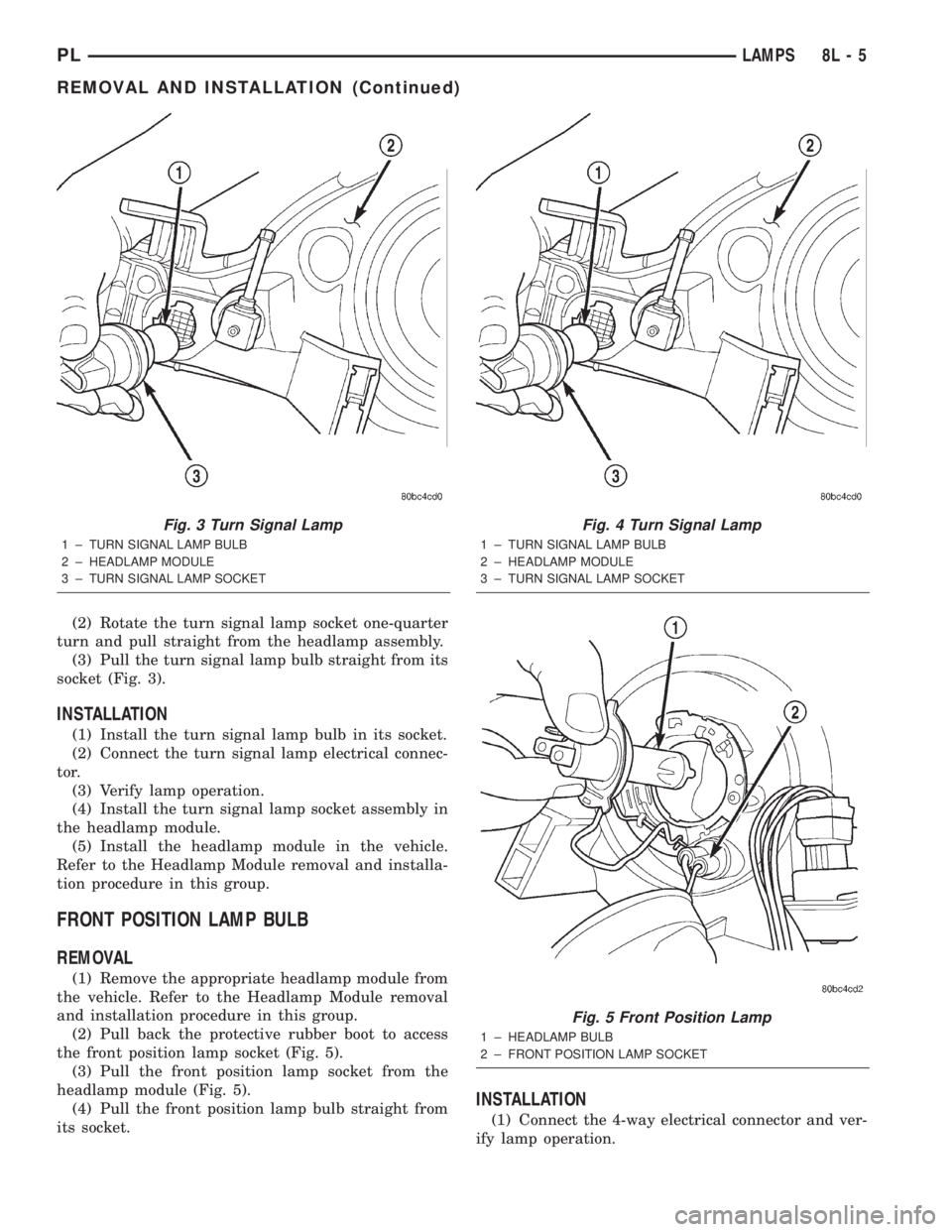
(2) Rotate the turn signal lamp socket one-quarter
turn and pull straight from the headlamp assembly.
(3) Pull the turn signal lamp bulb straight from its
socket (Fig. 3).
INSTALLATION
(1) Install the turn signal lamp bulb in its socket.
(2) Connect the turn signal lamp electrical connec-
tor.
(3) Verify lamp operation.
(4) Install the turn signal lamp socket assembly in
the headlamp module.
(5) Install the headlamp module in the vehicle.
Refer to the Headlamp Module removal and installa-
tion procedure in this group.
FRONT POSITION LAMP BULB
REMOVAL
(1) Remove the appropriate headlamp module from
the vehicle. Refer to the Headlamp Module removal
and installation procedure in this group.
(2) Pull back the protective rubber boot to access
the front position lamp socket (Fig. 5).
(3) Pull the front position lamp socket from the
headlamp module (Fig. 5).
(4) Pull the front position lamp bulb straight from
its socket.
INSTALLATION
(1) Connect the 4-way electrical connector and ver-
ify lamp operation.
Fig. 3 Turn Signal Lamp
1 ± TURN SIGNAL LAMP BULB
2 ± HEADLAMP MODULE
3 ± TURN SIGNAL LAMP SOCKET
Fig. 4 Turn Signal Lamp
1 ± TURN SIGNAL LAMP BULB
2 ± HEADLAMP MODULE
3 ± TURN SIGNAL LAMP SOCKET
Fig. 5 Front Position Lamp
1 ± HEADLAMP BULB
2 ± FRONT POSITION LAMP SOCKET
PLLAMPS 8L - 5
REMOVAL AND INSTALLATION (Continued)
Page 331 of 1285
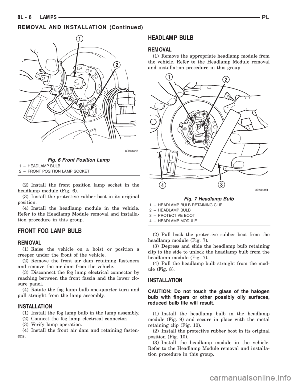
(2) Install the front position lamp socket in the
headlamp module (Fig. 6).
(3) Install the protective rubber boot in its original
position.
(4) Install the headlamp module in the vehicle.
Refer to the Headlamp Module removal and installa-
tion procedure in this group.
FRONT FOG LAMP BULB
REMOVAL
(1) Raise the vehicle on a hoist or position a
creeper under the front of the vehicle.
(2) Remove the front air dam retaining fasteners
and remove the air dam from the vehicle.
(3) Disconnect the fog lamp electrical connector by
reaching between the front fascia and the lower clo-
sure panel.
(4) Rotate the fog lamp bulb one-quarter turn and
pull straight from the lamp assembly.
INSTALLATION
(1) Install the fog lamp bulb in the lamp assembly.
(2) Connect the fog lamp electrical connector.
(3) Verify lamp operation.
(4) Install the front air dam and retaining fasten-
ers.
HEADLAMP BULB
REMOVAL
(1) Remove the appropriate headlamp module from
the vehicle. Refer to the Headlamp Module removal
and installation procedure in this group.
(2) Pull back the protective rubber boot from the
headlamp module (Fig. 7).
(3) Depress and slide the headlamp bulb retaining
clip to the side to unlock the headlamp bulb from the
headlamp module (Fig. 7).
(4) Pull the headlamp bulb straight from the mod-
ule (Fig. 8).
INSTALLATION
CAUTION: Do not touch the glass of the halogen
bulb with fingers or other possibly oily surfaces,
reduced bulb life will result.
(1) Install the headlamp bulb in the headlamp
module (Fig. 9) and secure in place with the metal
retaining clip (Fig. 10).
(2) Install the protective rubber boot in its original
position (Fig. 10).
(3) Install the headlamp module in the vehicle.
Refer to the Headlamp Module removal and installa-
tion procedure in this group.
Fig. 6 Front Position Lamp
1 ± HEADLAMP BULB
2 ± FRONT POSITION LAMP SOCKET
Fig. 7 Headlamp Bulb
1 ± HEADLAMP BULB RETAINING CLIP
2 ± HEADLAMP BULB
3 ± PROTECTIVE BOOT
4 ± HEADLAMP MODULE
8L - 6 LAMPSPL
REMOVAL AND INSTALLATION (Continued)
Page 335 of 1285
INSTALLATION
(1) Install the side repeater lamp bulb in its
socket.
(2) Verify lamp operation.
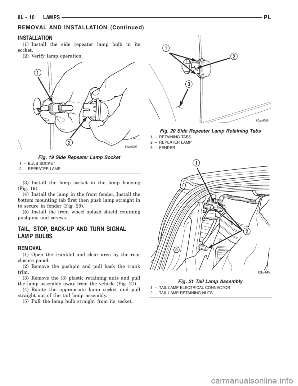
(3) Install the lamp socket in the lamp housing
(Fig. 19).
(4) Install the lamp in the front fender. Install the
bottom mounting tab first then push lamp straight in
to secure in fender (Fig. 20).
(5) Install the front wheel splash shield retaining
pushpins and screws.
TAIL, STOP, BACK-UP AND TURN SIGNAL
LAMP BULBS
REMOVAL
(1) Open the trunklid and clear area by the rear
closure panel.
(2) Remove the pushpin and pull back the trunk
trim.
(3) Remove the (3) plastic retaining nuts and pull
the lamp assembly away from the vehicle (Fig. 21).
(4) Rotate the appropriate lamp socket and pull
straight out of the tail lamp assembly.
(5) Pull the lamp bulb straight from its socket.
Fig. 19 Side Repeater Lamp Socket
1 ± BULB SOCKET
2 ± REPEATER LAMP
Fig. 20 Side Repeater Lamp Retaining Tabs
1 ± RETAINING TABS
2 ± REPEATER LAMP
3 ± FENDER
Fig. 21 Tail Lamp Assembly
1 ± TAIL LAMP ELECTRICAL CONNECTOR
2 ± TAIL LAMP RETAINING NUTS
8L - 10 LAMPSPL
REMOVAL AND INSTALLATION (Continued)
Page 336 of 1285
INSTALLATION
(1) Install the bulb in its socket.
(2) Verify lamp operation.
(3) Install the lamp socket in the tail lamp assem-
bly.
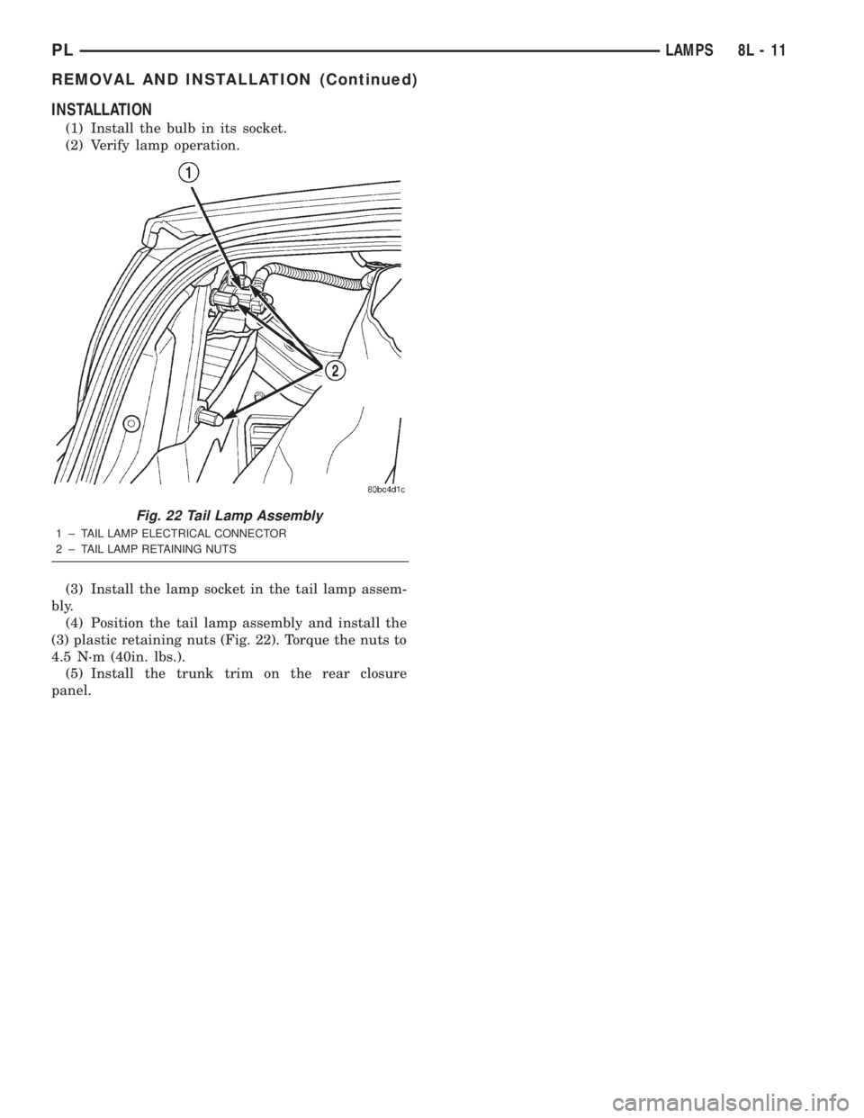
(4) Position the tail lamp assembly and install the
(3) plastic retaining nuts (Fig. 22). Torque the nuts to
4.5 N´m (40in. lbs.).
(5) Install the trunk trim on the rear closure
panel.
Fig. 22 Tail Lamp Assembly
1 ± TAIL LAMP ELECTRICAL CONNECTOR
2 ± TAIL LAMP RETAINING NUTS
PLLAMPS 8L - 11
REMOVAL AND INSTALLATION (Continued)