2000 DODGE NEON electrical
[x] Cancel search: electricalPage 337 of 1285
LAMP SERVICE
TABLE OF CONTENTS
page page
GENERAL INFORMATION
HEADLAMP SWITCH......................12
HEADLAMP LEVELING SWITCH.............12
HEADLAMP DIMMER SWITCH...............12
REMOVAL AND INSTALLATION
CENTER HIGH MOUNTED STOP LAMP
(CHMSL)..............................12HEADLAMP MODULE.....................12
HEADLAMP LEVELING MOTOR..............14
FRONT FOG LAMP.......................15
REAR LICENSE PLATE LAMPS..............15
REAR FOG LAMP........................15
SIDE REPEATER LAMP....................17
TAIL, STOP AND TURN SIGNAL LAMP........18
GENERAL INFORMATION
HEADLAMP SWITCH
Service procedures for the headlamp switch can be
found in Group 8E, Instrument Panel and Gauges.
More information can be found in Group 8W, Wiring
Diagrams.
HEADLAMP LEVELING SWITCH
Service procedures for the headlamp leveling
switch can be found in Group 8E, Instrument Panel
Systems. More information can be found in Group
8W, Wiring Diagrams.
HEADLAMP DIMMER SWITCH
The headlamp dimmer switch is incorporated into
the multi-function (turn signal) switch. Proper proce-
dures can be found in Group 8J, Turn Signal and
Flashers. More information can be found in Group
8W, Wiring Diagrams.
REMOVAL AND INSTALLATION
CENTER HIGH MOUNTED STOP LAMP
(CHMSL)
REMOVAL
(1) Open the trunklid
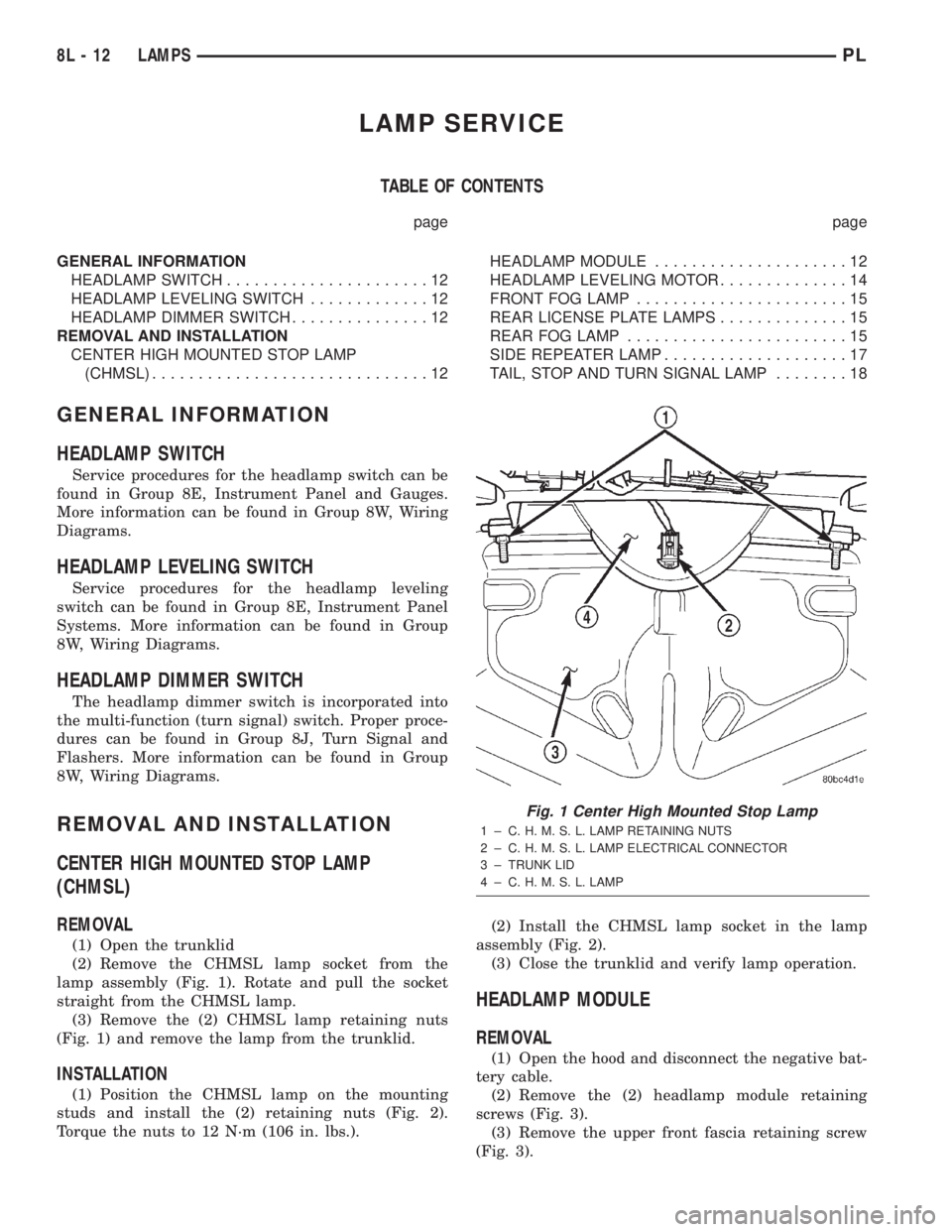
(2) Remove the CHMSL lamp socket from the
lamp assembly (Fig. 1). Rotate and pull the socket
straight from the CHMSL lamp.
(3) Remove the (2) CHMSL lamp retaining nuts
(Fig. 1) and remove the lamp from the trunklid.
INSTALLATION
(1) Position the CHMSL lamp on the mounting
studs and install the (2) retaining nuts (Fig. 2).
Torque the nuts to 12 N´m (106 in. lbs.).(2) Install the CHMSL lamp socket in the lamp
assembly (Fig. 2).
(3) Close the trunklid and verify lamp operation.
HEADLAMP MODULE
REMOVAL
(1) Open the hood and disconnect the negative bat-
tery cable.
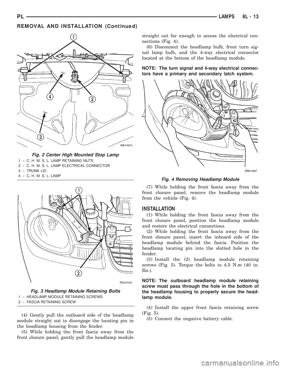
(2) Remove the (2) headlamp module retaining
screws (Fig. 3).
(3) Remove the upper front fascia retaining screw
(Fig. 3).
Fig. 1 Center High Mounted Stop Lamp
1 ± C. H. M. S. L. LAMP RETAINING NUTS
2 ± C. H. M. S. L. LAMP ELECTRICAL CONNECTOR
3 ± TRUNK LID
4 ± C. H. M. S. L. LAMP
8L - 12 LAMPSPL
Page 338 of 1285
(4) Gently pull the outboard side of the headlamp
module straight out to disengage the locating pin in
the headlamp housing from the fender.
(5) While holding the front fascia away from the
front closure panel, gently pull the headlamp modulestraight out far enough to access the electrical con-
nections (Fig. 4).
(6) Disconnect the headlamp bulb, front turn sig-
nal lamp bulb, and the 4-way electrical connector
located at the bottom of the headlamp module.
NOTE: The turn signal and 4-way electrical connec-
tors have a primary and secondary latch system.
(7) While holding the front fascia away from the
front closure panel, remove the headlamp module
from the vehicle (Fig. 4).
INSTALLATION
(1) While holding the front fascia away from the
front closure panel, position the headlamp module
and restore the electrical connections.
(2) While holding the front fascia away from the
front closure panel, insert the inboard side of the
headlamp module behind the fascia. Position the
headlamp locating pin into the slotted hole in the
fender.
(3) Install the (2) headlamp module retaining
screws (Fig. 5). Torque the bolts to 4.5 N´m (40 in.
lbs.).
NOTE: The outboard headlamp module retaining
screw must pass through the hole in the bottom of
the headlamp housing to properly secure the head-
lamp module.
(4) Install the upper front fascia retaining screw
(Fig. 5).
(5) Connect the negative battery cable.
Fig. 2 Center High Mounted Stop Lamp
1 ± C. H. M. S. L. LAMP RETAINING NUTS
2 ± C. H. M. S. L. LAMP ELECTRICAL CONNECTOR
3 ± TRUNK LID
4 ± C. H. M. S. L. LAMP
Fig. 3 Headlamp Module Retaining Bolts
1 ± HEADLAMP MODULE RETAINING SCREWS
2 ± FASCIA RETAINING SCREW
Fig. 4 Removing Headlamp Module
PLLAMPS 8L - 13
REMOVAL AND INSTALLATION (Continued)
Page 339 of 1285
HEADLAMP LEVELING MOTOR
REMOVAL
(1) Remove the appropriate headlamp module from
the vehicle. Refer to the HEADLAMP MODULE
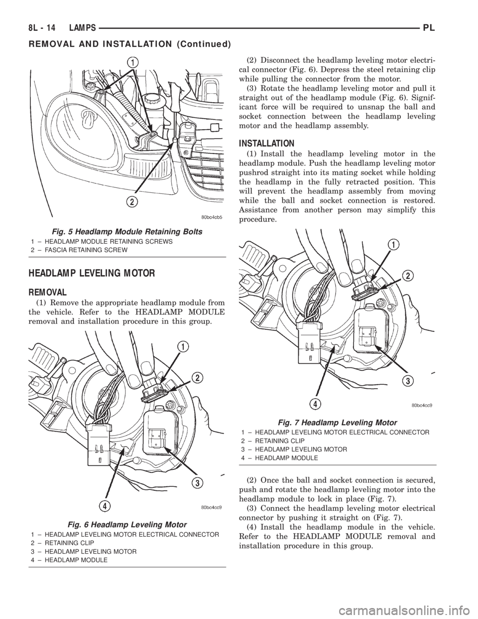
removal and installation procedure in this group.(2) Disconnect the headlamp leveling motor electri-
cal connector (Fig. 6). Depress the steel retaining clip
while pulling the connector from the motor.
(3) Rotate the headlamp leveling motor and pull it
straight out of the headlamp module (Fig. 6). Signif-
icant force will be required to unsnap the ball and
socket connection between the headlamp leveling
motor and the headlamp assembly.
INSTALLATION
(1) Install the headlamp leveling motor in the
headlamp module. Push the headlamp leveling motor
pushrod straight into its mating socket while holding
the headlamp in the fully retracted position. This
will prevent the headlamp assembly from moving
while the ball and socket connection is restored.
Assistance from another person may simplify this
procedure.
(2) Once the ball and socket connection is secured,
push and rotate the headlamp leveling motor into the
headlamp module to lock in place (Fig. 7).
(3) Connect the headlamp leveling motor electrical
connector by pushing it straight on (Fig. 7).
(4) Install the headlamp module in the vehicle.
Refer to the HEADLAMP MODULE removal and
installation procedure in this group.
Fig. 5 Headlamp Module Retaining Bolts
1 ± HEADLAMP MODULE RETAINING SCREWS
2 ± FASCIA RETAINING SCREW
Fig. 6 Headlamp Leveling Motor
1 ± HEADLAMP LEVELING MOTOR ELECTRICAL CONNECTOR
2 ± RETAINING CLIP
3 ± HEADLAMP LEVELING MOTOR
4 ± HEADLAMP MODULE
Fig. 7 Headlamp Leveling Motor
1 ± HEADLAMP LEVELING MOTOR ELECTRICAL CONNECTOR
2 ± RETAINING CLIP
3 ± HEADLAMP LEVELING MOTOR
4 ± HEADLAMP MODULE
8L - 14 LAMPSPL
REMOVAL AND INSTALLATION (Continued)
Page 340 of 1285
FRONT FOG LAMP
REMOVAL
(1) Raise the vehicle on a hoist or position a
creeper under the front of the vehicle.
(2) Remove the front air dam retaining fasteners
and remove the air dam from the vehicle.
(3) Disconnect the fog lamp electrical connector by
reaching between the front fascia and the lower clo-
sure panel.
(4) Remove the (3) fog lamp retaining nuts from
the lamp mounting studs.
(5) Remove the fog lamp from the front fascia.
INSTALLATION
(1) Position the fog lamp in the front fascia and
install the retaining nuts. Torque the nuts to 4.5 N´m
(40 in. lbs.).
(2) Connect the fog lamp electrical connector.
(3) Install the front air dam and retaining fasten-
ers.
REAR LICENSE PLATE LAMPS
REMOVAL
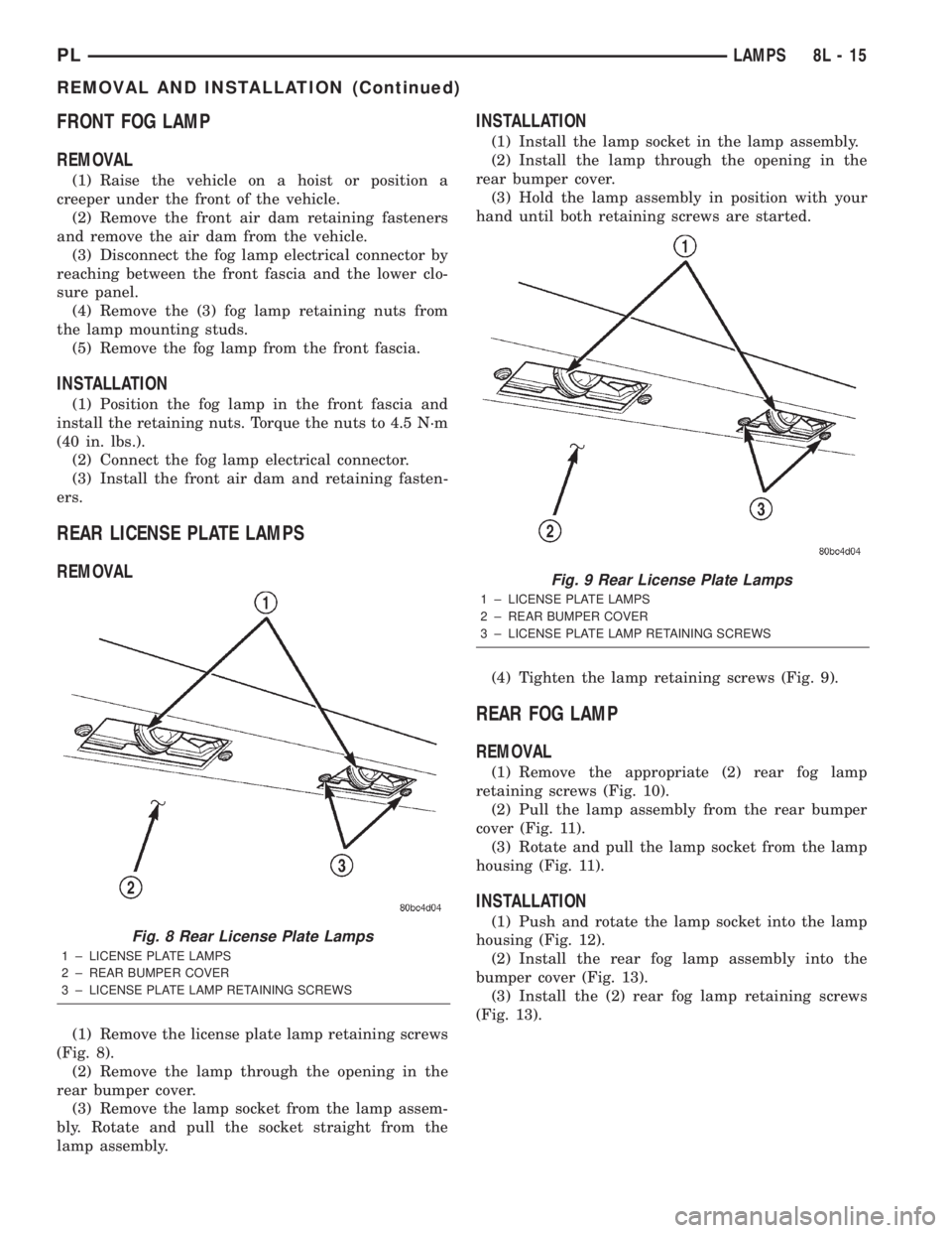
(1) Remove the license plate lamp retaining screws
(Fig. 8).
(2) Remove the lamp through the opening in the
rear bumper cover.
(3) Remove the lamp socket from the lamp assem-
bly. Rotate and pull the socket straight from the
lamp assembly.
INSTALLATION
(1) Install the lamp socket in the lamp assembly.
(2) Install the lamp through the opening in the
rear bumper cover.
(3) Hold the lamp assembly in position with your
hand until both retaining screws are started.
(4) Tighten the lamp retaining screws (Fig. 9).
REAR FOG LAMP
REMOVAL
(1) Remove the appropriate (2) rear fog lamp
retaining screws (Fig. 10).
(2) Pull the lamp assembly from the rear bumper
cover (Fig. 11).
(3) Rotate and pull the lamp socket from the lamp
housing (Fig. 11).
INSTALLATION
(1) Push and rotate the lamp socket into the lamp
housing (Fig. 12).
(2) Install the rear fog lamp assembly into the
bumper cover (Fig. 13).
(3) Install the (2) rear fog lamp retaining screws
(Fig. 13).Fig. 8 Rear License Plate Lamps
1 ± LICENSE PLATE LAMPS
2 ± REAR BUMPER COVER
3 ± LICENSE PLATE LAMP RETAINING SCREWS
Fig. 9 Rear License Plate Lamps
1 ± LICENSE PLATE LAMPS
2 ± REAR BUMPER COVER
3 ± LICENSE PLATE LAMP RETAINING SCREWS
PLLAMPS 8L - 15
REMOVAL AND INSTALLATION (Continued)
Page 343 of 1285
TAIL, STOP AND TURN SIGNAL LAMP
REMOVAL
(1) Open the trunklid and clear area by the rear
closure panel.
(2) Remove the pushpin and pull back the trunk
trim.
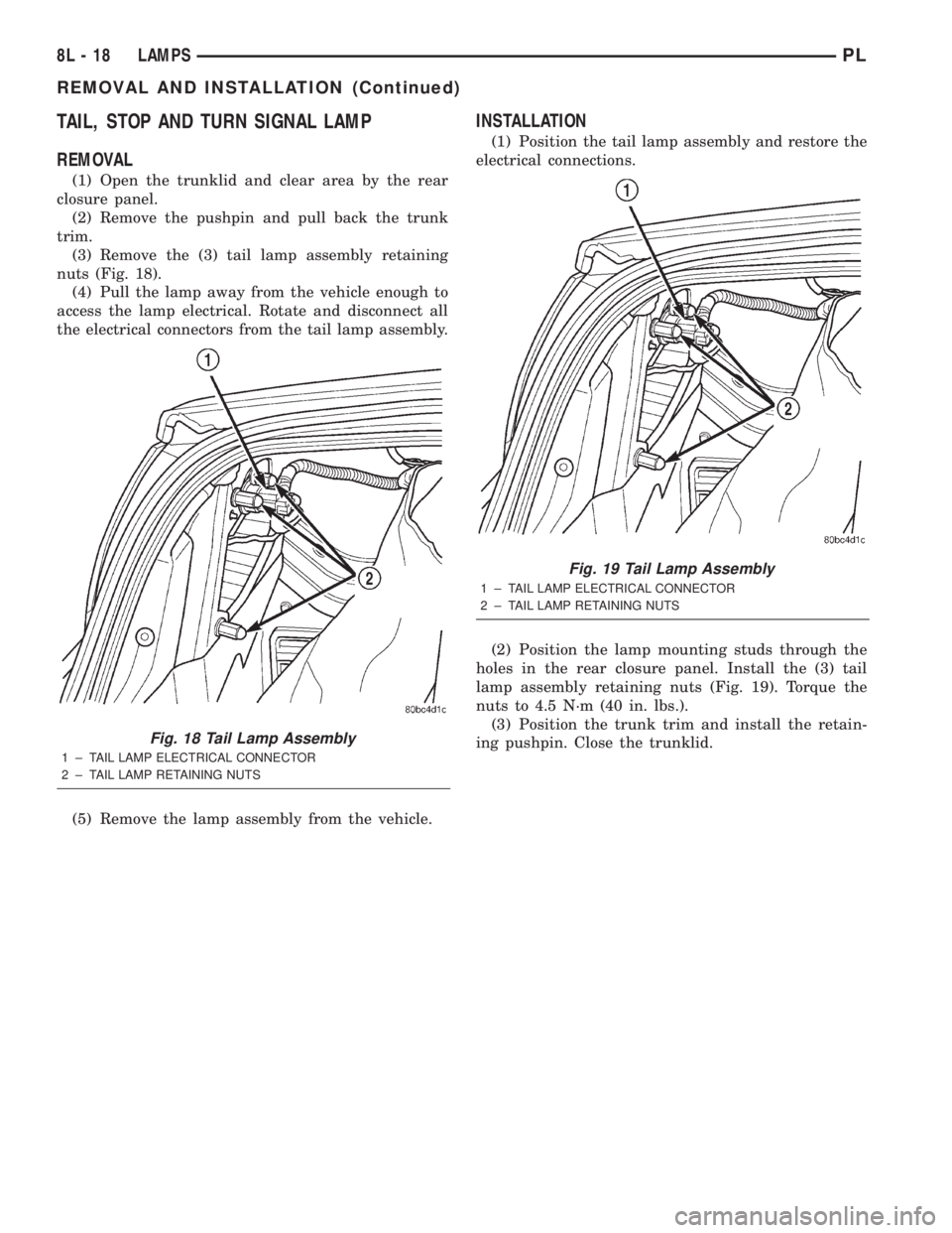
(3) Remove the (3) tail lamp assembly retaining
nuts (Fig. 18).
(4) Pull the lamp away from the vehicle enough to
access the lamp electrical. Rotate and disconnect all
the electrical connectors from the tail lamp assembly.
(5) Remove the lamp assembly from the vehicle.
INSTALLATION
(1) Position the tail lamp assembly and restore the
electrical connections.
(2) Position the lamp mounting studs through the
holes in the rear closure panel. Install the (3) tail
lamp assembly retaining nuts (Fig. 19). Torque the
nuts to 4.5 N´m (40 in. lbs.).
(3) Position the trunk trim and install the retain-
ing pushpin. Close the trunklid.
Fig. 18 Tail Lamp Assembly
1 ± TAIL LAMP ELECTRICAL CONNECTOR
2 ± TAIL LAMP RETAINING NUTS
Fig. 19 Tail Lamp Assembly
1 ± TAIL LAMP ELECTRICAL CONNECTOR
2 ± TAIL LAMP RETAINING NUTS
8L - 18 LAMPSPL
REMOVAL AND INSTALLATION (Continued)
Page 346 of 1285
PASSIVE RESTRAINT SYSTEMS
TABLE OF CONTENTS
page page
GENERAL INFORMATION
WARNINGS AND PRECAUTIONS.............1
DESCRIPTION AND OPERATION
AIRBAG CONTROL MODULE (ACM)..........1
CLOCKSPRING...........................2
DRIVER and PASSENGER AIRBAG MODULE....2
DIAGNOSIS AND TESTING
AIRBAG SYSTEM.........................3
SERVICE PROCEDURES
CLEAN UP PROCEDURE....................3HANDLING AIRBAG MODULES..............4
MAINTENANCE INSPECTION................4
REMOVAL AND INSTALLATION
AIRBAG CONTROL MODULE (ACM)..........4
CLOCKSPRING...........................5
DRIVER AIRBAG MODULE..................6
PASSENGER AIRBAG MODULE..............7
STEERING WHEEL........................8
ADJUSTMENTS
CLOCKSPRING CENTERING PROCEDURE......9
GENERAL INFORMATION
WARNINGS AND PRECAUTIONS
WARNING: THIS SYSTEM IS A SENSITIVE, COM-
PLEX ELECTRO±MECHANICAL UNIT. DISCONNECT
AND ISOLATE THE BATTERY NEGATIVE CABLE
BEFORE BEGINNING AIRBAG SYSTEM COMPO-
NENT REMOVAL OR INSTALLATION PROCEDURES.
THIS WILL DISABLE THE AIRBAG SYSTEM. FAIL-
URE TO DISCONNECT THE BATTERY COULD
RESULT IN ACCIDENTAL AIRBAG DEPLOYMENT
AND POSSIBLE PERSONAL INJURY.
ALLOW SYSTEM CAPACITOR TO DISCHARGE
FOR ONE MINUTE BEFORE REMOVING AIRBAG
COMPONENTS.
DO NOT PLACE AN INTACT UNDEPLOYED AIRBAG
FACE DOWN ON A SOLID SURFACE, THE AIRBAG
WILL PROPEL INTO THE AIR IF ACCIDENTALLY
DEPLOYED AND COULD RESULT IN PERSONAL
INJURY. WHEN CARRYING OR HANDLING AN UNDE-
PLOYED AIRBAG MODULE, THE TRIM SIDE OF THE
AIRBAG SHOULD BE POINTING AWAY FROM THE
BODY TO MINIMIZE POSSIBILITY OF INJURY IF ACCI-
DENTAL DEPLOYMENT OCCURS.
REPLACE AIRBAG SYSTEM COMPONENTS WITH
MOPARTREPLACEMENT PARTS. SUBSTITUTE
PARTS MAY APPEAR INTERCHANGEABLE, BUT
INTERNAL DIFFERENCES MAY RESULT IN INFE-
RIOR OCCUPANT PROTECTION.
WEAR SAFETY GLASSES, RUBBER GLOVES,
AND LONG SLEEVES CLOTHING WHEN CLEANING
POWDER RESIDUE FROM VEHICLE AFTER AIRBAG
DEPLOYMENT. SODIUM HYDROXIDE POWDER
RESIDUE EMITTED FROM A DEPLOYED AIRBAG
CAN CAUSE SKIN IRRITATION. FLUSH AFFECTEDAREA WITH COOL WATER IF IRRITATION IS EXPE-
RIENCED. IF NASAL OR THROAT IRRITATION IS
EXPERIENCED, EXIT THE VEHICLE FOR FRESH AIR
UNTIL THE IRRITATION CEASES. IF IRRITATION
CONTINUES, SEE A PHYSICIAN.
DO NOT USE A REPLACEMENT AIRBAG THAT IS
NOT IN THE ORIGINAL PACKAGING, IMPROPER
DEPLOYMENT AND PERSONAL INJURY CAN
RESULT.
THE FACTORY INSTALLED FASTENERS,
SCREWS AND BOLTS USED TO FASTEN AIRBAG
COMPONENTS HAVE A SPECIAL COATING AND
ARE SPECIFICALLY DESIGNED FOR THE AIRBAG
SYSTEM. DO NOT USE SUBSTITUTE FASTENERS,
USE ONLY ORIGINAL EQUIPMENT FASTENERS
LISTED IN THE PARTS CATALOG WHEN FASTENER
REPLACEMENT IS REQUIRED.
NOTE: Airbags should be stored in a cool dry loca-
tion away from excessive heat and static electrical
activity with the fabric airbag facing UP, or a prema-
ture deployment can result.
If the Driver/Passenger Airbag Module is defective
and not deployed, refer to DaimlerChrysler Corpora-
tion current return list for proper handling proce-
dures.
DESCRIPTION AND OPERATION
AIRBAG CONTROL MODULE (ACM)
The Airbag Control Module (ACM) contains the
sensing element, safing sensor, and energy reserve
capacitor. The module is mounted on the tunnel/floor
pan between the gear shift lever and the park brake
PLPASSIVE RESTRAINT SYSTEMS 8M - 1
Page 347 of 1285
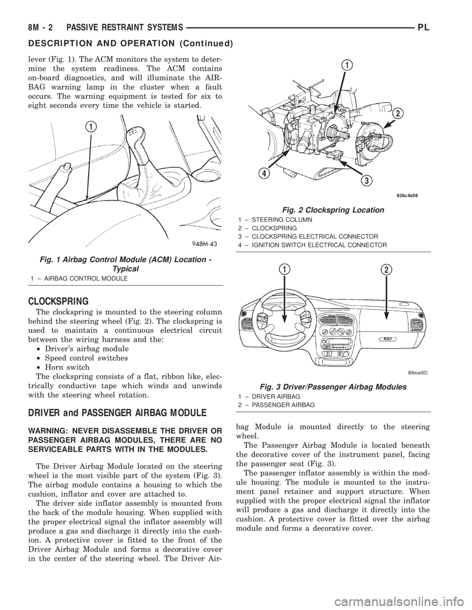
lever (Fig. 1). The ACM monitors the system to deter-
mine the system readiness. The ACM contains
on-board diagnostics, and will illuminate the AIR-
BAG warning lamp in the cluster when a fault
occurs. The warning equipment is tested for six to
eight seconds every time the vehicle is started.
CLOCKSPRING
The clockspring is mounted to the steering column
behind the steering wheel (Fig. 2). The clockspring is
used to maintain a continuous electrical circuit
between the wiring harness and the:
²Driver's airbag module
²Speed control switches
²Horn switch
The clockspring consists of a flat, ribbon like, elec-
trically conductive tape which winds and unwinds
with the steering wheel rotation.
DRIVER and PASSENGER AIRBAG MODULE
WARNING: NEVER DISASSEMBLE THE DRIVER OR
PASSENGER AIRBAG MODULES, THERE ARE NO
SERVICEABLE PARTS WITH IN THE MODULES.
The Driver Airbag Module located on the steering
wheel is the most visible part of the system (Fig. 3).
The airbag module contains a housing to which the
cushion, inflator and cover are attached to.
The driver side inflator assembly is mounted from
the back of the module housing. When supplied with
the proper electrical signal the inflator assembly will
produce a gas and discharge it directly into the cush-
ion. A protective cover is fitted to the front of the
Driver Airbag Module and forms a decorative cover
in the center of the steering wheel. The Driver Air-bag Module is mounted directly to the steering
wheel.
The Passenger Airbag Module is located beneath
the decorative cover of the instrument panel, facing
the passenger seat (Fig. 3).
The passenger inflator assembly is within the mod-
ule housing. The module is mounted to the instru-
ment panel retainer and support structure. When
supplied with the proper electrical signal the inflator
will produce a gas and discharge it directly into the
cushion. A protective cover is fitted over the airbag
module and forms a decorative cover.
Fig. 1 Airbag Control Module (ACM) Location -
Typical
1 ± AIRBAG CONTROL MODULE
Fig. 2 Clockspring Location
1 ± STEERING COLUMN
2 ± CLOCKSPRING
3 ± CLOCKSPRING ELECTRICAL CONNECTOR
4 ± IGNITION SWITCH ELECTRICAL CONNECTOR
Fig. 3 Driver/Passenger Airbag Modules
1 ± DRIVER AIRBAG
2 ± PASSENGER AIRBAG
8M - 2 PASSIVE RESTRAINT SYSTEMSPL
DESCRIPTION AND OPERATION (Continued)
Page 349 of 1285
²Clockspring assembly
²Steering Column Assembly w/Lower Steering
Column Coupler
PASSENGER AIRBAG
After a Passenger Airbag Module has been
deployed, replace the following components because
they cannot be reused.
²Passenger Airbag Module
Inspect all the attaching hardware and instrument
panel for damage. If damage is evident, components
should be replaced.
HANDLING AIRBAG MODULES
DEPLOYED AIRBAG MODULE
The vehicle interior may contain a very small
amount of sodium hydroxide powder, a by-product of
airbag deployment. Sodium hydroxide powder can
irritate the skin, eyes, nose and throat. Wear safety
glasses, rubber gloves, and long sleeved clothing
when cleaning any of the powder residue from the
vehicle.
If you find that the cleanup is irritating your skin,
run cool water over the affected area. Also, if you
experience nasal or throat irritation, exit the vehicle
for fresh air until the irritation ceases. If irritation
continues, see a physician.
UNDEPLOYED AIRBAG MODULE
The airbag modules must be stored in its original
special container until used for service. At no time
should a source of electricity be permitted near the
inflator on the back of an airbag module. When car-
rying or handling an undeployed airbag module, the
trim side of the airbag should be pointing away from
the body to minimize possibility of injury if acciden-
tal deployment occurs. Do not place undeployed air-
bag face down on a solid surface, the airbag will
propel into the air if accidentally deployment occurs.
MAINTENANCE INSPECTION
(1) Check the airbag warning lamp for proper
operation as follows:
(a) Turn ignition switch to the ON position, the
airbag warning lamp should light. If not, test the
system using a DRB llltscan tool and the proper
Body Diagnostic Procedures Manual.
(b) The airbag warning lamp lights, but fails to
go out after eight seconds. Test the system using a
DRB llltscan tool and the proper Body Diagnostic
Procedures Manual.
(c) After correcting active malfunction erase
stored Diagnostic Trouble Codes (DTC's).
REMOVAL AND INSTALLATION
AIRBAG CONTROL MODULE (ACM)
WARNING: THE ACM CONTAINS THE SENSING
ELEMENT AND A SAFING SENSOR WHICH
ENABLES THE SYSTEM TO DEPLOY THE AIR-
BAGS. TO AVOID ACCIDENTAL DEPLOYMENT,
NEVER CONNECT ACM ELECTRICALLY TO THE
SYSTEM WHILE VEHICLE BATTERY IS CON-
NECTED.
DISCONNECT AND ISOLATE THE BATTERY NEG-
ATIVE (GROUND) CABLE BEFORE BEGINNING ANY
AIRBAG SYSTEM COMPONENT REMOVAL OR
INSTALLATION PROCEDURE. THIS WILL DISABLE
THE AIRBAG SYSTEM. FAILURE TO DISCONNECT
BATTERY COULD RESULT IN ACCIDENTAL AIRBAG
DEPLOYMENT AND POSSIBLE PERSONAL INJURY.
ALLOW SYSTEM CAPACITOR TO DISCHARGE
FOR 1 MINUTE BEFORE REMOVING ANY AIRBAG
COMPONENTS.
REMOVAL
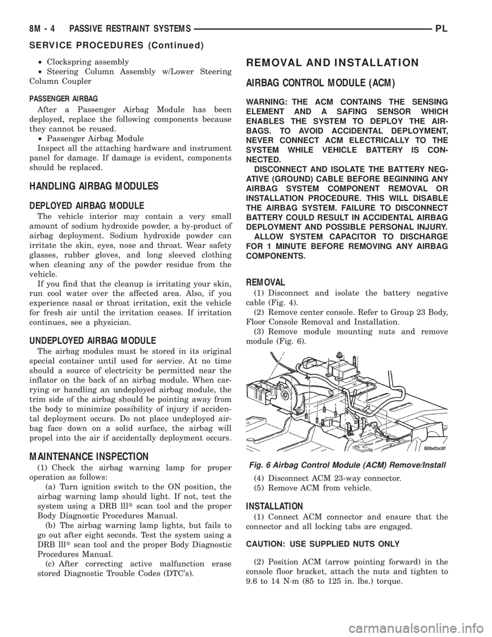
(1) Disconnect and isolate the battery negative
cable (Fig. 4).
(2) Remove center console. Refer to Group 23 Body,
Floor Console Removal and Installation.
(3) Remove module mounting nuts and remove
module (Fig. 6).
(4) Disconnect ACM 23-way connector.
(5) Remove ACM from vehicle.
INSTALLATION
(1) Connect ACM connector and ensure that the
connector and all locking tabs are engaged.
CAUTION: USE SUPPLIED NUTS ONLY
(2) Position ACM (arrow pointing forward) in the
console floor bracket, attach the nuts and tighten to
9.6 to 14 N´m (85 to 125 in. lbs.) torque.
Fig. 6 Airbag Control Module (ACM) Remove/Install
8M - 4 PASSIVE RESTRAINT SYSTEMSPL
SERVICE PROCEDURES (Continued)