2000 DODGE NEON electrical
[x] Cancel search: electricalPage 232 of 1285
CHARGING SYSTEM
TABLE OF CONTENTS
page page
DESCRIPTION AND OPERATION
CHARGING SYSTEM.......................1
GENERATOR.............................1
ELECTRONIC VOLTAGE REGULATOR..........1
REMOVAL AND INSTALLATION
GENERATOR.............................2SPECIFICATIONS
GENERATOR RATINGS.....................3
TORQUE................................3
DESCRIPTION AND OPERATION
CHARGING SYSTEM
DESCRIPTION
The charging system consists of:
²Generator
²Electronic Voltage Regulator (EVR) circuitry
within the Powertrain Control Module (PCM)
²Ignition switch (refer to the Ignition System for
information)
²Battery (refer to the Battery for information)
²Battery temperature sensor
²Wiring harness and connections (refer to the
Wiring for information)
OPERATION
The charging system is turned on and off with the
ignition switch. When the ignition switch is turned to
the ON position, battery voltage is applied to the
generator rotor through one of the two field termi-
nals to produce a magnetic field. The generator is
driven by the engine through a serpentine belt and
pulley arrangement.
The amount of DC current produced by the gener-
ator is controlled by the EVR (field control) circuitry,
contained within the PCM. This circuitry is con-
nected in series with the second rotor field terminal
and ground.
Temperature data, along with data from monitored
line voltage, is used by the PCM to vary the battery
charging rate. This is done by cycling the ground
path to control the strength of the rotor magnetic
field. The PCM then compensates and regulates gen-
erator current output accordingly and to maintain
the proper voltage depending on battery tempera-
ture.
All vehicles are equipped with On-Board Diagnos-
tics (OBD). All OBD-sensed systems, including the
EVR (field control) circuitry, are monitored by thePCM. Each monitored circuit is assigned a Diagnos-
tic Trouble Code (DTC). The PCM will store a DTC in
electronic memory for any failure it detects.
GENERATOR
DESCRIPTION
The generator is belt-driven by the engine. It is
serviced only as a complete assembly. If the genera-
tor fails for any reason, the entire assembly must be
replaced.
OPERATION
As the energized rotor begins to rotate within the
generator, the spinning magnetic field induces a cur-
rent into the windings of the stator coil. Once the
generator begins producing sufficient current, it also
provides the current needed to energize the rotor.
The Y type stator winding connections deliver the
induced AC current to 3 positive and 3 negative
diodes for rectification. From the diodes, rectified DC
current is delivered to the vehicles electrical system
through the generator, battery, and ground terminals.
Noise emitting from the generator may be caused
by:
²Worn, loose or defective bearings
²Loose or defective drive pulley
²Incorrect, worn, damaged or misadjusted drive
belt
²Loose mounting bolts
²Misaligned drive pulley
²Defective stator or diode
²Damaged internal fins
ELECTRONIC VOLTAGE REGULATOR
DESCRIPTION
The Electronic Voltage Regulator (EVR) is not a
separate component. It is actually a voltage regulat-
ing circuit located within the Powertrain Control
PLCHARGING SYSTEM 8C - 1
Page 236 of 1285
IGNITION SYSTEM
TABLE OF CONTENTS
page page
DESCRIPTION AND OPERATION
IGNITION SYSTEM........................1
SPARK PLUGS...........................1
SPARK PLUG CABLES.....................1
ELECTRONIC IGNITION COILS...............2
AUTOMATIC SHUTDOWN RELAY.............2
CRANKSHAFT POSITION SENSORÐPCM
INPUT................................3
CAMSHAFT POSITION SENSORÐPCM
INPUT................................4
KNOCK SENSOR..........................5
IGNITION SWITCH........................5
LOCK KEY CYLINDER......................5
IGNITION INTERLOCK.....................6
REMOVAL AND INSTALLATION
SPARK PLUG SERVICE....................6SPARK PLUG CABLE SERVICE..............6
IGNITION COIL...........................6
AUTOMATIC SHUTDOWN RELAY.............6
CAMSHAFT POSITION SENSOR..............6
CRANKSHAFT POSITION SENSOR............8
KNOCK SENSOR..........................8
IGNITION SWITCH........................8
LOCK KEY CYLINDER......................9
IGNITION INTERLOCK....................10
SPECIFICATIONS
VECI LABEL............................10
FIRING ORDERÐ2.0L....................10
TORQUE SPECIFICATION..................11
SPARK PLUG CABLE RESISTANCEÐSOHC....11
SPARK PLUG...........................11
IGNITION COIL..........................11
DESCRIPTION AND OPERATION
IGNITION SYSTEM
DESCRIPTION
The system's three main components are the coil
pack, crankshaft position sensor, and camshaft posi-
tion sensor.
OPERATION
Basic ignition timing is not adjustable.The
Powertrain Control Module (PCM) determines spark
advance. The 2.0L engines use a fixed ignition timing
system. The distributorless electronic ignition system
is referred to as the Direct Ignition System (DIS).
SPARK PLUGS
The 2.0L engines uses resistor spark plugs. For
spark plug identification and specifications, Refer to
the Specifications section at the end of this group.
Remove the spark plugs and examine them for
burned electrodes and fouled, cracked or broken por-
celain insulators. Keep plugs arranged in the order
in which they were removed from the engine. An iso-
lated plug displaying an abnormal condition indicates
that a problem exists in the corresponding cylinder.
Spark plugs that have low mileage may be cleaned
and reused if not otherwise defective. Refer to the
Spark Plug Condition section of this group. Aftercleaning, file the center electrode flat with a small
point file or jewelers file. Adjust the gap between the
electrodes (Fig. 1) to the dimensions specified in the
chart at the end of this section by bending the
ground electrode (just above the attachment weld)
with the appropriate tool.
Never apply any force between the electrode or
damage to the center electrode assembly will result.
Always tighten spark plugs to the specified torque.
Over tightening can cause distortion and damage.
Tighten spark plugs to 28 N´m (20 ft. lbs.) torque.
SPARK PLUG CABLES
Spark plug cables are sometimes referred to as sec-
ondary ignition wires. The wires transfer electrical
current from the coil pack to individual spark plugs
at each cylinder. The resistor type, nonmetallic spark
plug cables provide suppression of radio frequency
emissions from the ignition system.
Check the spark plug cable connections for good
contact at the coil and spark plugs. Terminals should
be fully seated. The nipples and spark plug covers
should be in good condition. Nipples should fit tightly
on the coil. Spark plug boot should completely cover
the spark plug hole in the cylinder head cover. Install
the boot until the terminal snaps over the spark
plug. A snap must be felt to ensure the spark plug
cable terminal engaged the spark plug.
PLIGNITION SYSTEM 8D - 1
Page 241 of 1285
IGNITION INTERLOCK
OPERATION
All vehicles equipped with automatic transaxles
have an interlock system. The system prevents shift-
ing the vehicle out of Park unless the ignition lock
cylinder is in the Off, Run or Start position. In addi-
tion, the operator cannot rotate the key to the lock
position unless the shifter is in the park position. On
vehicles equipped with floor shift refer to the - Tran-
saxle for Automatic Transmission Shifter/Ignition
Interlock.
REMOVAL AND INSTALLATION
SPARK PLUG SERVICE
Failure to route the cables properly could cause the
radio to reproduce ignition noise, cross ignition of the
spark plugs or short circuit the cables to ground.
REMOVAL
REMOVE CABLES FROM COIL FIRST.
Always remove the spark plug cable by grasping
the top of the spark plug insulator, turning the boot
1/2 turn and pulling straight up in a steady motion.
(1) Remove the spark plug using a quality socket
with a rubber or foam insert.
(2) Inspect the spark plug condition.
INSTALLATION
(1) To avoid cross threading, start the spark plug
into the cylinder head by hand.
(2) Tighten spark plugs to 28 N´m (20 ft. lbs.)
torque.
(3) Install spark plug insulators over spark plugs.
Ensure the top of the spark plug insulator covers the
upper end of the spark plug tube.
Reconnect to coil.
SPARK PLUG CABLE SERVICE
Failure to route the cables properly could cause the
radio to reproduce ignition noise, cross ignition of the
spark plugs or short circuit the cables to ground.
REMOVAL
Remove spark plug cable from coil first.
Always remove the spark plug cable by grasping
the top of the spark plug insulator, turning the boot
1/2 turn and pulling straight up in a steady motion.
INSTALLATION
Install spark plug insulators over spark plugs.
Ensure the top of the spark plug insulator covers the
upper end of the spark plug tube. The connect theother end to coil pack. Be sure that dual plastic clip
holds the cables off of the valve cover.
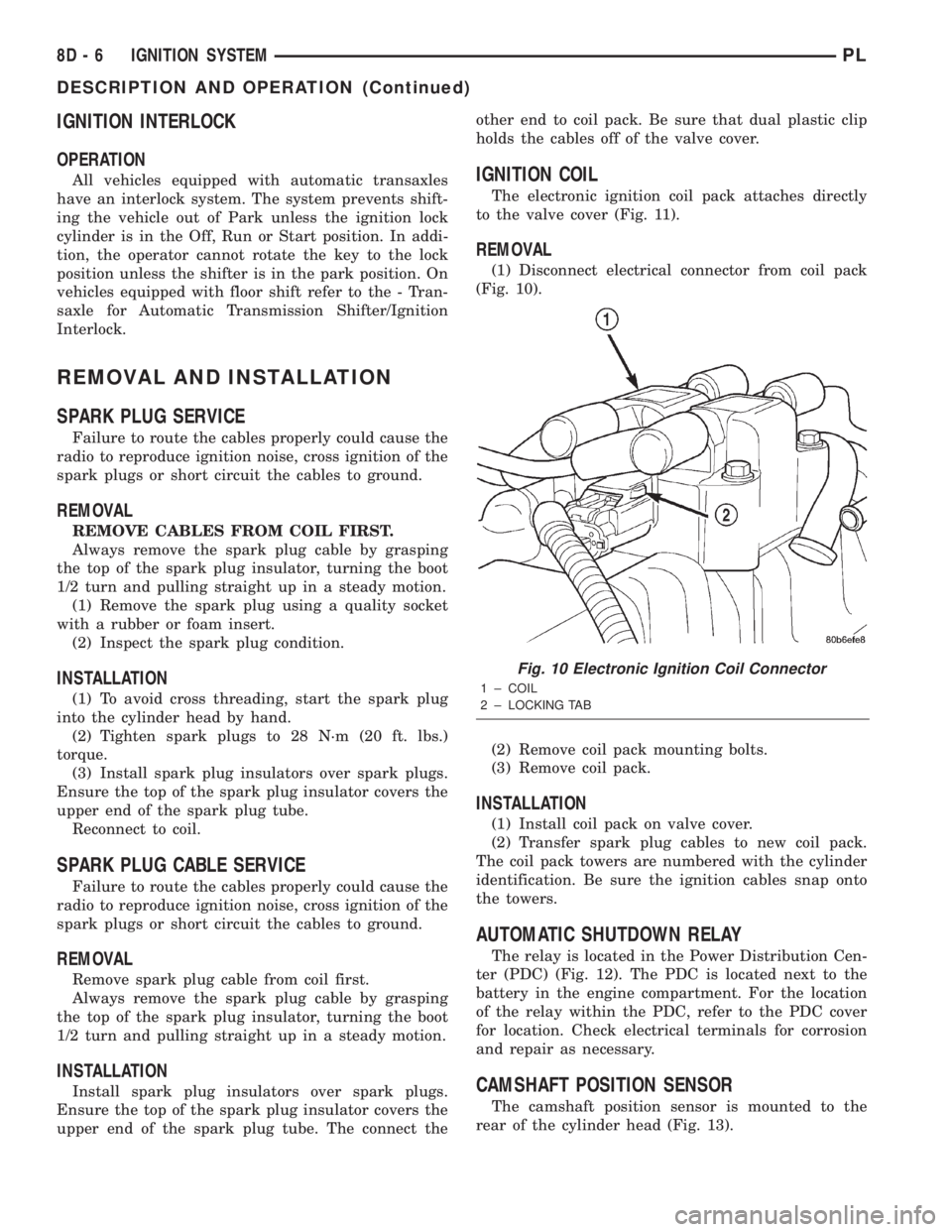
IGNITION COIL
The electronic ignition coil pack attaches directly
to the valve cover (Fig. 11).
REMOVAL
(1) Disconnect electrical connector from coil pack
(Fig. 10).
(2) Remove coil pack mounting bolts.
(3) Remove coil pack.
INSTALLATION
(1) Install coil pack on valve cover.
(2) Transfer spark plug cables to new coil pack.
The coil pack towers are numbered with the cylinder
identification. Be sure the ignition cables snap onto
the towers.
AUTOMATIC SHUTDOWN RELAY
The relay is located in the Power Distribution Cen-
ter (PDC) (Fig. 12). The PDC is located next to the
battery in the engine compartment. For the location
of the relay within the PDC, refer to the PDC cover
for location. Check electrical terminals for corrosion
and repair as necessary.
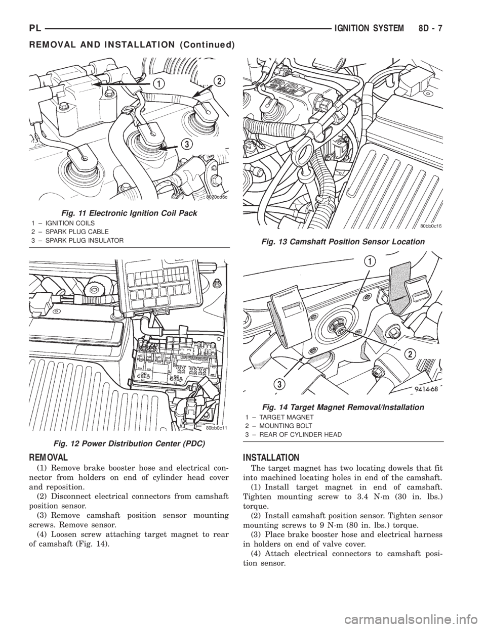
CAMSHAFT POSITION SENSOR
The camshaft position sensor is mounted to the
rear of the cylinder head (Fig. 13).
Fig. 10 Electronic Ignition Coil Connector
1 ± COIL
2 ± LOCKING TAB
8D - 6 IGNITION SYSTEMPL
DESCRIPTION AND OPERATION (Continued)
Page 242 of 1285
REMOVAL
(1) Remove brake booster hose and electrical con-
nector from holders on end of cylinder head cover
and reposition.
(2) Disconnect electrical connectors from camshaft
position sensor.
(3) Remove camshaft position sensor mounting
screws. Remove sensor.
(4) Loosen screw attaching target magnet to rear
of camshaft (Fig. 14).
INSTALLATION
The target magnet has two locating dowels that fit
into machined locating holes in end of the camshaft.
(1) Install target magnet in end of camshaft.
Tighten mounting screw to 3.4 N´m (30 in. lbs.)
torque.
(2) Install camshaft position sensor. Tighten sensor
mounting screws to 9 N´m (80 in. lbs.) torque.
(3) Place brake booster hose and electrical harness
in holders on end of valve cover.
(4) Attach electrical connectors to camshaft posi-
tion sensor.
Fig. 11 Electronic Ignition Coil Pack
1 ± IGNITION COILS
2 ± SPARK PLUG CABLE
3 ± SPARK PLUG INSULATOR
Fig. 12 Power Distribution Center (PDC)
Fig. 13 Camshaft Position Sensor Location
Fig. 14 Target Magnet Removal/Installation
1 ± TARGET MAGNET
2 ± MOUNTING BOLT
3 ± REAR OF CYLINDER HEAD
PLIGNITION SYSTEM 8D - 7
REMOVAL AND INSTALLATION (Continued)
Page 243 of 1285
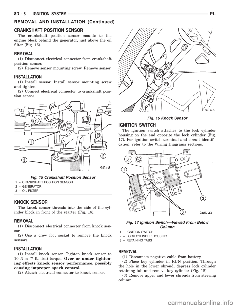
CRANKSHAFT POSITION SENSOR
The crankshaft position sensor mounts to the
engine block behind the generator, just above the oil
filter (Fig. 15).
REMOVAL
(1) Disconnect electrical connector from crankshaft
position sensor.
(2) Remove sensor mounting screw. Remove sensor.
INSTALLATION
(1) Install sensor. Install sensor mounting screw
and tighten.
(2) Connect electrical connector to crankshaft posi-
tion sensor.
KNOCK SENSOR
The knock sensor threads into the side of the cyl-
inder block in front of the starter (Fig. 16).
REMOVAL
(1) Disconnect electrical connector from knock sen-
sor.
(2) Use a crow foot socket to remove the knock
sensors.
INSTALLATION
(1) Install knock sensor. Tighten knock sensor to
10 N´m (7 ft. lbs.) torque.Over or under tighten-
ing effects knock sensor performance, possibly
causing improper spark control.
(2) Attach electrical connector to knock sensor.
IGNITION SWITCH
The ignition switch attaches to the lock cylinder
housing on the end opposite the lock cylinder (Fig.
17). For ignition switch terminal and circuit identifi-
cation, refer to the Wiring Diagrams sections.
REMOVAL
(1) Disconnect negative cable from battery.
(2) Place key cylinder in RUN position. Through
the hole in the lower shroud, depress lock cylinder
retaining tab and remove key cylinder (Fig. 18).
(3) Remove upper and lower shrouds from steering
column.
Fig. 15 Crankshaft Position Sensor
1 ± CRANKSHAFT POSITION SENSOR
2 ± GENERATOR
3 ± OIL FILTER
Fig. 16 Knock Sensor
Fig. 17 Ignition SwitchÐViewed From Below
Column
1 ± IGNITION SWITCH
2 ± LOCK CYLINDER HOUSING
3 ± RETAINING TABS
8D - 8 IGNITION SYSTEMPL
REMOVAL AND INSTALLATION (Continued)
Page 244 of 1285
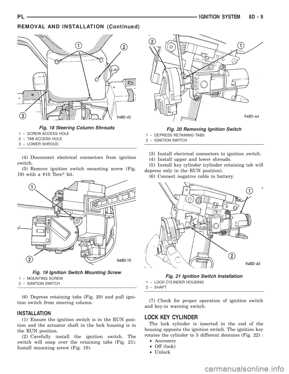
(4) Disconnect electrical connectors from ignition
switch.
(5) Remove ignition switch mounting screw (Fig.
19) with a #10 Torxtbit.
(6) Depress retaining tabs (Fig. 20) and pull igni-
tion switch from steering column.
INSTALLATION
(1) Ensure the ignition switch is in the RUN posi-
tion and the actuator shaft in the lock housing is in
the RUN position.
(2) Carefully install the ignition switch. The
switch will snap over the retaining tabs (Fig. 21).
Install mounting screw (Fig. 19).(3) Install electrical connectors to ignition switch.
(4) Install upper and lower shrouds.
(5) Install key cylinder (cylinder retaining tab will
depress only in the RUN position).
(6) Connect negative cable to battery.
(7) Check for proper operation of ignition switch
and key-in warning switch.LOCK KEY CYLINDER
The lock cylinder is inserted in the end of the
housing opposite the ignition switch. The ignition key
rotates the cylinder to 5 different detentes (Fig. 22) :
²Accessory
²Off (lock)
²Unlock
Fig. 18 Steering Column Shrouds
1 ± SCREW ACCESS HOLE
2 ± TAB ACCESS HOLE
3 ± LOWER SHROUD
Fig. 19 Ignition Switch Mounting Screw
1 ± MOUNTING SCREW
2 ± IGNITION SWITCH
Fig. 20 Removing Ignition Switch
1 ± DEPRESS RETAINING TABS
2 ± IGNITION SWITCH
Fig. 21 Ignition Switch Installation
1 ± LOCK CYLINDER HOUSING
2 ± SHAFT
PLIGNITION SYSTEM 8D - 9
REMOVAL AND INSTALLATION (Continued)
Page 261 of 1285
REMOVAL AND INSTALLATION
HEADLAMP LEVELING SWITCH
REMOVAL
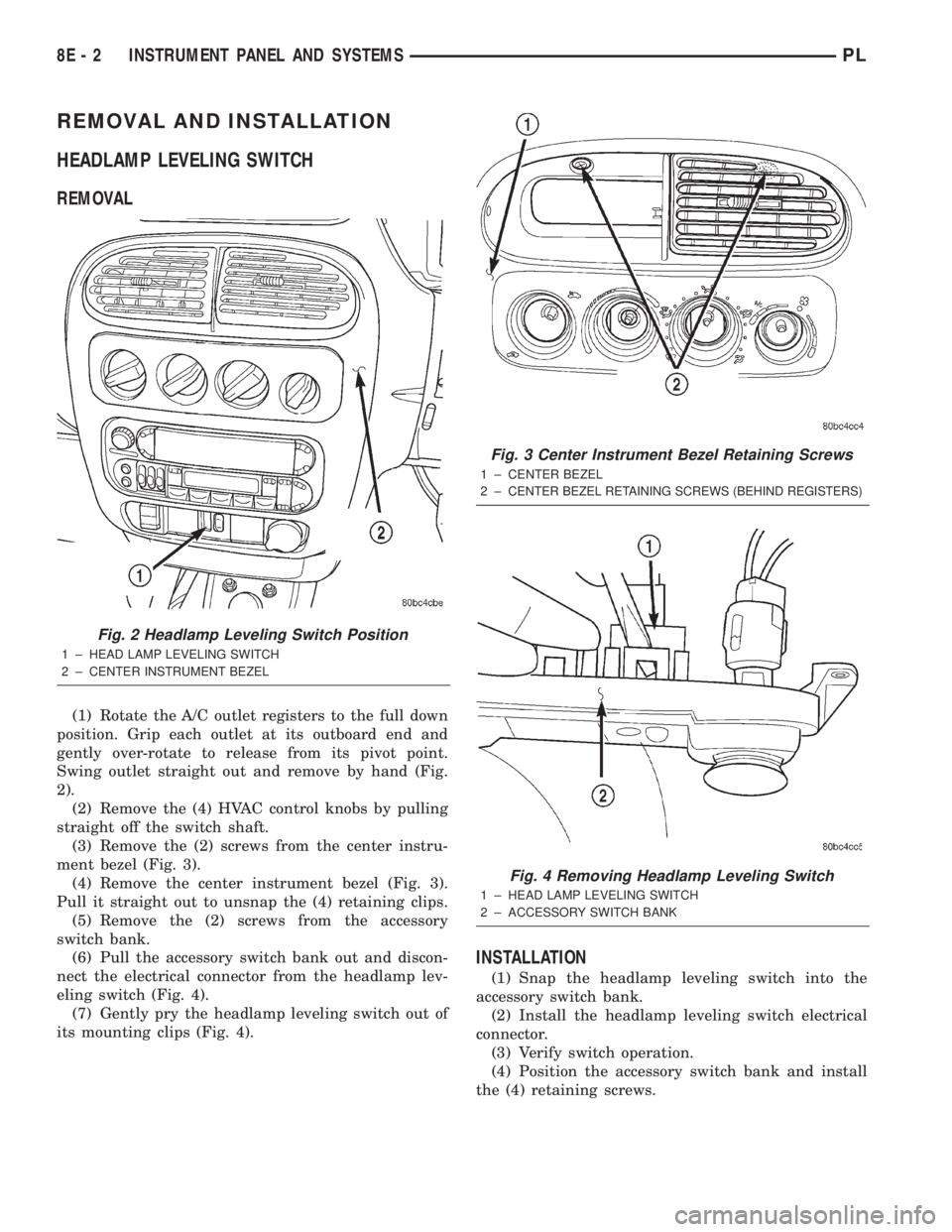
(1) Rotate the A/C outlet registers to the full down
position. Grip each outlet at its outboard end and
gently over-rotate to release from its pivot point.
Swing outlet straight out and remove by hand (Fig.
2).
(2) Remove the (4) HVAC control knobs by pulling
straight off the switch shaft.
(3) Remove the (2) screws from the center instru-
ment bezel (Fig. 3).
(4) Remove the center instrument bezel (Fig. 3).
Pull it straight out to unsnap the (4) retaining clips.
(5) Remove the (2) screws from the accessory
switch bank.
(6) Pull the accessory switch bank out and discon-
nect the electrical connector from the headlamp lev-
eling switch (Fig. 4).
(7) Gently pry the headlamp leveling switch out of
its mounting clips (Fig. 4).
INSTALLATION
(1) Snap the headlamp leveling switch into the
accessory switch bank.
(2) Install the headlamp leveling switch electrical
connector.
(3) Verify switch operation.
(4) Position the accessory switch bank and install
the (4) retaining screws.
Fig. 2 Headlamp Leveling Switch Position
1 ± HEAD LAMP LEVELING SWITCH
2 ± CENTER INSTRUMENT BEZEL
Fig. 3 Center Instrument Bezel Retaining Screws
1 ± CENTER BEZEL
2±
CENTER BEZEL RETAINING SCREWS (BEHIND REGISTERS)
Fig. 4 Removing Headlamp Leveling Switch
1 ± HEAD LAMP LEVELING SWITCH
2 ± ACCESSORY SWITCH BANK
8E - 2 INSTRUMENT PANEL AND SYSTEMSPL
Page 288 of 1285
On most vehicles another resistor has been added
to the at rest circuit causing the PCM to never see 5
volts. This was done for diagnostic purposes. If the
switch circuit should open (bad connection) then the
PCM will see the 5 volts and know the circuit is bad.
The PCM will then set an open circuit fault.
STOP LAMP SWITCH
DESCRIPTION
The switch is mounted on the brake pedal mount-
ing bracket under the instrument panel.
OPERATION
Vehicles equipped with the speed control option use
a dual function stop lamp switch. The PCM monitors
the state of the dual function stop lamp switch. Refer
to the Brake section for more information on stop
lamp switch service and adjustment procedures.
The brake switch is equipped with three sets of
contacts, one normally open and the other two nor-
mally closed (brakes disengaged). The PCM sends a
12 volt signal to one of the normally closed contacts
in the brake switch, which is connected to a ground.
With the contacts closed, the 12 volt signal is pulled
to ground causing the signal to go low. The low volt-
age signal, monitored by the PCM, indicates that the
brakes are not applied. When the brakes are applied,
the contacts open, causing the PCM's output voltage
to go high, disengaging the speed control also
grounding the dump solenoid.
The second set of normally closed contacts is sup-
plied battery voltage any time speed control is
selected. From the brake switch, current is routed to
the speed control servo solenoids. The speed control
solenoids (vacuum, vent and dump) are provided this
current any time the speed control is ON and the
brakes are disengaged. When the driver applies the
brakes, the contacts open and current is interrupted
to the solenoids. The normally open contacts are fed
battery voltage. When the brakes are applied, battery
voltage is supplied to the stop lamps.
SERVO CABLE
DESCRIPTION
The speed control servo cable is connected between
the speed control vacuum servo diaphragm and the
throttle body control linkage.
OPERATION
This cable causes the throttle control linkage to
open or close the throttle valve in response to move-
ment of the vacuum servo diaphragm.
VACUUM RESERVOIR
OPERATION
The reservoir stores engine vacuum in the reser-
voir. When engine vacuum drops, as in climbing a
grade while driving, the reservoir supplies the vac-
uum needed to maintain proper speed control opera-
tion. The vacuum reservoir cannot be repaired and
must be replaced if faulty.
VEHICLE SPEED SENSOR
The Vehicle Speed Sensor (VSS) is a pulse genera-
tor mounted to an adapter near the transmission out-
put shaft. The sensor is driven through the adapter
by a speedometer pinion gear. The VSS pulse signal
to the speedometer/odometer is monitored by the
PCM speed control circuitry to determine vehicle
speed and to maintain speed control set speed.
REMOVAL AND INSTALLATION
SPEED CONTROL SERVO
REMOVAL
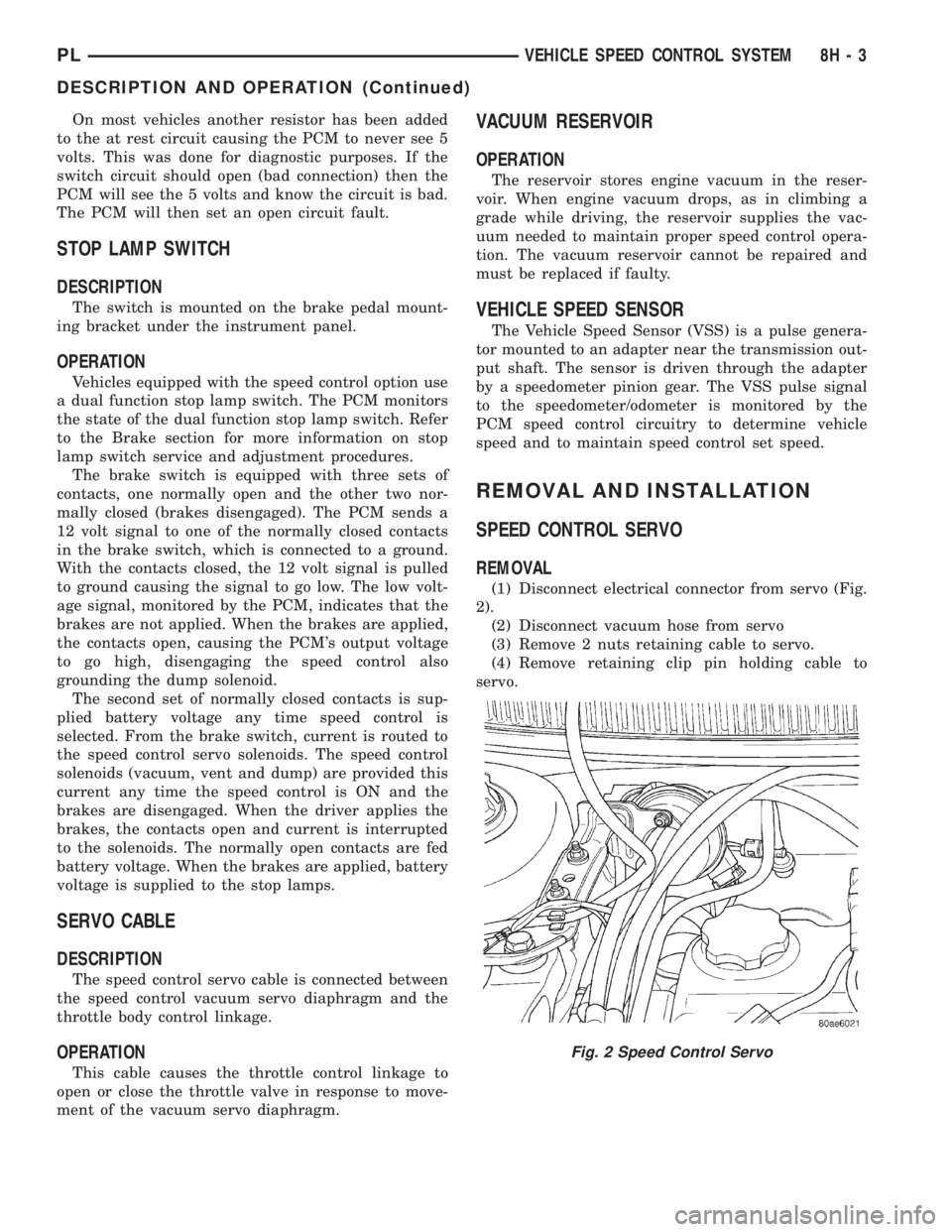
(1) Disconnect electrical connector from servo (Fig.
2).
(2) Disconnect vacuum hose from servo
(3) Remove 2 nuts retaining cable to servo.
(4) Remove retaining clip pin holding cable to
servo.
Fig. 2 Speed Control Servo
PLVEHICLE SPEED CONTROL SYSTEM 8H - 3
DESCRIPTION AND OPERATION (Continued)