2000 DODGE NEON coil pack
[x] Cancel search: coil packPage 236 of 1285
IGNITION SYSTEM
TABLE OF CONTENTS
page page
DESCRIPTION AND OPERATION
IGNITION SYSTEM........................1
SPARK PLUGS...........................1
SPARK PLUG CABLES.....................1
ELECTRONIC IGNITION COILS...............2
AUTOMATIC SHUTDOWN RELAY.............2
CRANKSHAFT POSITION SENSORÐPCM
INPUT................................3
CAMSHAFT POSITION SENSORÐPCM
INPUT................................4
KNOCK SENSOR..........................5
IGNITION SWITCH........................5
LOCK KEY CYLINDER......................5
IGNITION INTERLOCK.....................6
REMOVAL AND INSTALLATION
SPARK PLUG SERVICE....................6SPARK PLUG CABLE SERVICE..............6
IGNITION COIL...........................6
AUTOMATIC SHUTDOWN RELAY.............6
CAMSHAFT POSITION SENSOR..............6
CRANKSHAFT POSITION SENSOR............8
KNOCK SENSOR..........................8
IGNITION SWITCH........................8
LOCK KEY CYLINDER......................9
IGNITION INTERLOCK....................10
SPECIFICATIONS
VECI LABEL............................10
FIRING ORDERÐ2.0L....................10
TORQUE SPECIFICATION..................11
SPARK PLUG CABLE RESISTANCEÐSOHC....11
SPARK PLUG...........................11
IGNITION COIL..........................11
DESCRIPTION AND OPERATION
IGNITION SYSTEM
DESCRIPTION
The system's three main components are the coil
pack, crankshaft position sensor, and camshaft posi-
tion sensor.
OPERATION
Basic ignition timing is not adjustable.The
Powertrain Control Module (PCM) determines spark
advance. The 2.0L engines use a fixed ignition timing
system. The distributorless electronic ignition system
is referred to as the Direct Ignition System (DIS).
SPARK PLUGS
The 2.0L engines uses resistor spark plugs. For
spark plug identification and specifications, Refer to
the Specifications section at the end of this group.
Remove the spark plugs and examine them for
burned electrodes and fouled, cracked or broken por-
celain insulators. Keep plugs arranged in the order
in which they were removed from the engine. An iso-
lated plug displaying an abnormal condition indicates
that a problem exists in the corresponding cylinder.
Spark plugs that have low mileage may be cleaned
and reused if not otherwise defective. Refer to the
Spark Plug Condition section of this group. Aftercleaning, file the center electrode flat with a small
point file or jewelers file. Adjust the gap between the
electrodes (Fig. 1) to the dimensions specified in the
chart at the end of this section by bending the
ground electrode (just above the attachment weld)
with the appropriate tool.
Never apply any force between the electrode or
damage to the center electrode assembly will result.
Always tighten spark plugs to the specified torque.
Over tightening can cause distortion and damage.
Tighten spark plugs to 28 N´m (20 ft. lbs.) torque.
SPARK PLUG CABLES
Spark plug cables are sometimes referred to as sec-
ondary ignition wires. The wires transfer electrical
current from the coil pack to individual spark plugs
at each cylinder. The resistor type, nonmetallic spark
plug cables provide suppression of radio frequency
emissions from the ignition system.
Check the spark plug cable connections for good
contact at the coil and spark plugs. Terminals should
be fully seated. The nipples and spark plug covers
should be in good condition. Nipples should fit tightly
on the coil. Spark plug boot should completely cover
the spark plug hole in the cylinder head cover. Install
the boot until the terminal snaps over the spark
plug. A snap must be felt to ensure the spark plug
cable terminal engaged the spark plug.
PLIGNITION SYSTEM 8D - 1
Page 237 of 1285

Loose cable connections will corrode, increase resis-
tance and permit water to enter the coil towers.
These conditions can cause ignition malfunction.
Plastic clips in various locations protect the cables
from damage. When the cables are replaced the clips
must be used to prevent damage to the cables, and
should be rotated about 30É below the horizontal.
ELECTRONIC IGNITION COILS
DESCRIPTION
The coil pack consists of 2 coils molded together.
The coil pack is mounted on the valve cover (Fig. 2).
OPERATION
WARNING: THE DIRECT IGNITION SYSTEM GEN-
ERATES APPROXIMATELY 40,000 VOLTS. PER-
SONAL INJURY COULD RESULT FROM CONTACT
WITH THIS SYSTEM.
High tension leads route to each cylinder from the
coil. The coil fires two spark plugs every power
stroke. One plug is the cylinder under compression,
the other cylinder fires on the exhaust stroke. Coil
number one fires cylinders 1 and 4. Coil number two
fires cylinders 2 and 3. The PCM determines which
of the coils to charge and fire at the correct time.
The Auto Shutdown (ASD) relay provides battery
voltage to the ignition coil. The PCM provides a
ground contact (circuit) for energizing the coil. When
the PCM breaks the contact, the energy in the coil
primary transfers to the secondary causing thespark. The PCM will de-energize the ASD relay if it
does not receive the crankshaft position sensor and
camshaft position sensor inputs. Refer to Auto Shut-
down (ASD) RelayÐPCM Output, in this section for
relay operation.
AUTOMATIC SHUTDOWN RELAY
DESCRIPTION
The ASD relay is located in the PDC (Fig. 3). The
inside top of the PDC cover has label showing relay
and fuse identification.
Fig. 1 Checking Spark Plug Electrode Gap
1 ± TAPER GAUGE
Fig. 2 Ignition Coil Pack
1 ± IGNITION COILS
2 ± SPARK PLUG CABLE
3 ± SPARK PLUG INSULATOR
Fig. 3 Power Distribution Center (PDC)
8D - 2 IGNITION SYSTEMPL
DESCRIPTION AND OPERATION (Continued)
Page 241 of 1285
IGNITION INTERLOCK
OPERATION
All vehicles equipped with automatic transaxles
have an interlock system. The system prevents shift-
ing the vehicle out of Park unless the ignition lock
cylinder is in the Off, Run or Start position. In addi-
tion, the operator cannot rotate the key to the lock
position unless the shifter is in the park position. On
vehicles equipped with floor shift refer to the - Tran-
saxle for Automatic Transmission Shifter/Ignition
Interlock.
REMOVAL AND INSTALLATION
SPARK PLUG SERVICE
Failure to route the cables properly could cause the
radio to reproduce ignition noise, cross ignition of the
spark plugs or short circuit the cables to ground.
REMOVAL
REMOVE CABLES FROM COIL FIRST.
Always remove the spark plug cable by grasping
the top of the spark plug insulator, turning the boot
1/2 turn and pulling straight up in a steady motion.
(1) Remove the spark plug using a quality socket
with a rubber or foam insert.
(2) Inspect the spark plug condition.
INSTALLATION
(1) To avoid cross threading, start the spark plug
into the cylinder head by hand.
(2) Tighten spark plugs to 28 N´m (20 ft. lbs.)
torque.
(3) Install spark plug insulators over spark plugs.
Ensure the top of the spark plug insulator covers the
upper end of the spark plug tube.
Reconnect to coil.
SPARK PLUG CABLE SERVICE
Failure to route the cables properly could cause the
radio to reproduce ignition noise, cross ignition of the
spark plugs or short circuit the cables to ground.
REMOVAL
Remove spark plug cable from coil first.
Always remove the spark plug cable by grasping
the top of the spark plug insulator, turning the boot
1/2 turn and pulling straight up in a steady motion.
INSTALLATION
Install spark plug insulators over spark plugs.
Ensure the top of the spark plug insulator covers the
upper end of the spark plug tube. The connect theother end to coil pack. Be sure that dual plastic clip
holds the cables off of the valve cover.
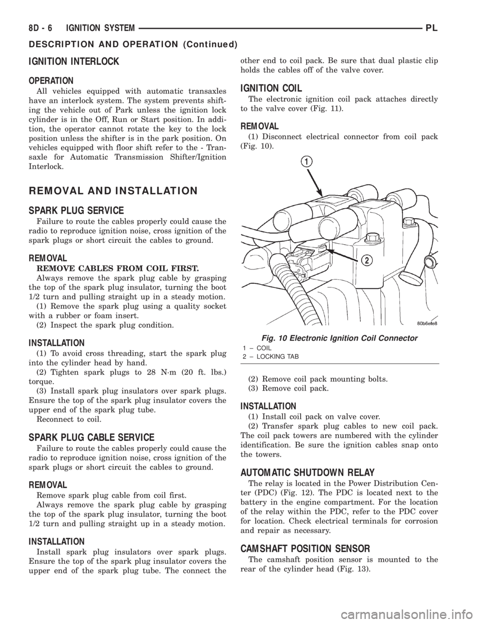
IGNITION COIL
The electronic ignition coil pack attaches directly
to the valve cover (Fig. 11).
REMOVAL
(1) Disconnect electrical connector from coil pack
(Fig. 10).
(2) Remove coil pack mounting bolts.
(3) Remove coil pack.
INSTALLATION
(1) Install coil pack on valve cover.
(2) Transfer spark plug cables to new coil pack.
The coil pack towers are numbered with the cylinder
identification. Be sure the ignition cables snap onto
the towers.
AUTOMATIC SHUTDOWN RELAY
The relay is located in the Power Distribution Cen-
ter (PDC) (Fig. 12). The PDC is located next to the
battery in the engine compartment. For the location
of the relay within the PDC, refer to the PDC cover
for location. Check electrical terminals for corrosion
and repair as necessary.
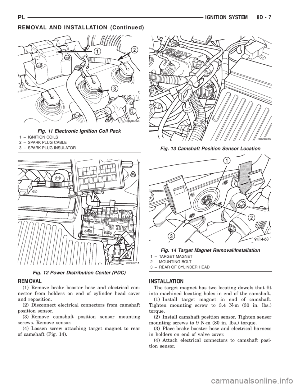
CAMSHAFT POSITION SENSOR
The camshaft position sensor is mounted to the
rear of the cylinder head (Fig. 13).
Fig. 10 Electronic Ignition Coil Connector
1 ± COIL
2 ± LOCKING TAB
8D - 6 IGNITION SYSTEMPL
DESCRIPTION AND OPERATION (Continued)
Page 242 of 1285
REMOVAL
(1) Remove brake booster hose and electrical con-
nector from holders on end of cylinder head cover
and reposition.
(2) Disconnect electrical connectors from camshaft
position sensor.
(3) Remove camshaft position sensor mounting
screws. Remove sensor.
(4) Loosen screw attaching target magnet to rear
of camshaft (Fig. 14).
INSTALLATION
The target magnet has two locating dowels that fit
into machined locating holes in end of the camshaft.
(1) Install target magnet in end of camshaft.
Tighten mounting screw to 3.4 N´m (30 in. lbs.)
torque.
(2) Install camshaft position sensor. Tighten sensor
mounting screws to 9 N´m (80 in. lbs.) torque.
(3) Place brake booster hose and electrical harness
in holders on end of valve cover.
(4) Attach electrical connectors to camshaft posi-
tion sensor.
Fig. 11 Electronic Ignition Coil Pack
1 ± IGNITION COILS
2 ± SPARK PLUG CABLE
3 ± SPARK PLUG INSULATOR
Fig. 12 Power Distribution Center (PDC)
Fig. 13 Camshaft Position Sensor Location
Fig. 14 Target Magnet Removal/Installation
1 ± TARGET MAGNET
2 ± MOUNTING BOLT
3 ± REAR OF CYLINDER HEAD
PLIGNITION SYSTEM 8D - 7
REMOVAL AND INSTALLATION (Continued)
Page 728 of 1285

²When checking #2 main bearing shim #1 & #3
main bearing.
²When checking #3 main bearing shim #2 & #4
main bearing.
²When checking #4 main bearing shim #3 main
bearing.
NOTE: REMOVE ALL SHIMS BEFORE REASSEM-
BLING ENGINE
ALTERNATIVE METHOD
The weight of the crankshaft can be supported by a
jack under the counterweight adjacent to the bearing
being checked.
PLASTIGAGE PROCEDURE
(1) Remove oil film from surface to be checked.
Plastigage is soluble in oil.
(2) Place a piece of Plastigage across the entire
width of the bearing shell in the cap approximately
6.35 mm (1/4 in.) off center and away from the oil
holes (Fig. 5). (In addition, suspected areas can be
checked by placing the Plastigage in the suspected
area). Torque the bearing cap bolts of the bearing
being checked to the proper specifications.
(3) Remove the bearing cap and compare the width
of the flattened Plastigage (Fig. 6) with the metric
scale provided on the package. Locate the band clos-
est to the same width. This band shows the amount
of clearance in thousandths of a millimeter. Differ-
ences in readings between the ends indicate the
amount of taper present. Record all readings taken.
Refer to Engine Specifications.Plastigage gener-
ally is accompanied by two scales. One scale is
in inches, the other is a metric scale.
NOTE: Plastigage is available in a variety of clear-
ance ranges. Use the most appropriate range for
the specifications you are checking.
CONNECTING ROD BEARING CLEARANCE
Engine connecting rod bearing clearances can be
determined by use of Plastigage or equivalent. Thefollowing is the recommended procedure for the use
of Plastigage:
(1) Rotate the crankshaft until the connecting rod
to be checked is at the bottom of its stroke.
(2) Remove oil film from surface to be checked.
Plastigage is soluble in oil.
(3) Place a piece of Plastigage across the entire
width of the bearing shell in the bearing cap approx-
imately 6.35 mm (1/4 in.) off center and away from
the oil hole (Fig. 5). In addition, suspect areas can be
checked by placing plastigage in that area.
(4) Assemble the rod cap with Plastigage in place.
Tighten the rod cap to the specified torque.Do not
rotate the crankshaft while assembling the cap
or the Plastigage may be smeared, giving inac-
curate results.
(5) Remove the bearing cap and compare the width
of the flattened Plastigage (Fig. 6) with the scale pro-
vided on the package. Locate the band closest to the
same width. This band indicates the amount of oil
clearance. Differences in readings between the ends
indicate the amount of taper present. Record all
readings taken. Refer to Engine Specifications.Plas-
tigage generally is accompanied by two scales.
One scale is in inches, the other is a metric
scale. If the bearing clearance exceeds wear
limit specification, replace the bearing.
REPAIR OF DAMAGED OR WORN THREADS
Damaged or worn threads (including aluminum
head spark plug threads) can be repaired. Essen-
tially, this repair consists of drilling out worn or
damaged threads, tapping the hole with a special
Heli-Coil Tap, (or equivalent) and installing an insert
into the tapped hole. This brings the hole back to its
original thread size.
CAUTION: Be sure that the tapped holes maintain
the original centerline.
Heli-Coil tools and inserts are readily available
from automotive parts jobbers.
HYDROSTATIC LOCKED ENGINE
When an engine is suspected to be hydrostatically
locked, regardless of what caused the problem, the
following steps should be used.
CAUTION: DO NOT use starter motor to rotate the
engine, severe damage may occur.
(1) Inspect air cleaner, induction system and
intake manifold to insure system is dry and clear of
foreign material.
(2) Remove negative battery cable.
(3) Place a shop towel around the spark plugs
when removing them from the engine. This will catch
Fig. 6 Clearance Measurement
PLENGINE 9 - 5
GENERAL INFORMATION (Continued)
Page 760 of 1285
CYLINDER HEAD
REMOVAL
(1) Perform fuel system pressure release procedure
before attempting any repairs.Refer to Group 14,
Fuel System
(2) Disconnect negative battery cable.
(3) Remove power steering/air conditioning drive
belt. Refer to Group 7, Cooling System Accessory
Drive for procedure.
(4) Raise vehicle.
(5) Drain cooling system. Refer to Group 7, Cooling
System.
(6) Remove exhaust pipe from manifold.
(7) Remove right front wheel.
(8) Remove right side splash shield.
(9) Remove generator belt. Refer to Group 7, Cool-
ing System Accessory Drive Belts for procedure.
(10) Remove crankshaft damper. Refer to proce-
dure in this section.
(11) Remove lower torque strut.
(12) Lower vehicle and remove upper torque strut.
(13) Remove ground strap and power steering hose
support clip from engine mount bracket.
(14) Remove power steering pump assembly and
set aside.
(15) Support engine from beneath with a suitable
jack.
(16) Remove right side engine mount to bracket
through bolt.
(17) Remove the lower engine mount bracket bolt.
Raise engine slightly and remove the upper engine
mount bracket bolts.(18) Remove engine mount bracket. This procedure
may require additional raising/lowering of engine
until bracket will clear engine components.
(19) Remove front timing belt cover.
(20) Rotate engine until timing marks are aligned.
(21) Remove timing belt and tensioner. Refer to
procedures in this section.
(22) Remove camshaft sprocket. Refer to proce-
dures in this section.
(23) Remove rear timing belt cover.
(24) Disconnect fuel line at fuel rail.
(25) Remove coolant recovery container.
(26) Remove ground wire to cylinder head.
(27) Remove upper radiator hose.
(28) Remove intake manifold. Refer to procedure
in this section.
(29) Disconnect ignition coil electrical connector.
Remove coil pack and spark plug cables from engine.
(30) Remove Crankcase Closed Ventilation (CCV)
hose from cylinder head cover.
(31) Disconnect cam sensor and coolant tempera-
ture electrical connectors.
(32) Remove heater tube to cylinder head attach-
ing fasteners.
(33) Remove heater hose from thermostat housing
connector.
(34) Remove cylinder head cover.
(35) Remove cylinder head bolts.
(36) Remove cylinder head and gasket (Fig. 55).
PL2.0L SOHC ENGINE 9 - 37
REMOVAL AND INSTALLATION (Continued)
Page 862 of 1285
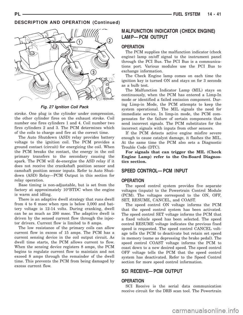
stroke. One plug is the cylinder under compression,
the other cylinder fires on the exhaust stroke. Coil
number one fires cylinders 1 and 4. Coil number two
fires cylinders 2 and 3. The PCM determines which
of the coils to charge and fire at the correct time.
The Auto Shutdown (ASD) relay provides battery
voltage to the ignition coil. The PCM provides a
ground contact (circuit) for energizing the coil. When
the PCM breaks the contact, the energy in the coil
primary transfers to the secondary causing the
spark. The PCM will de-energize the ASD relay if it
does not receive the crankshaft position sensor and
camshaft position sensor inputs. Refer to Auto Shut-
down (ASD) RelayÐPCM Output in this section for
relay operation.
Base timing is non-adjustable, but is set from the
factory at approximately 10ÉBTDC when the engine
is warm and idling.
There is an adaptive dwell strategy that runs dwell
from 4 to 6 msec when rpm is below 3,000 and bat-
tery voltage is 12-14 volts. During cranking, dwell
can be as much as 200 msec. The adaptive dwell is
driven by the sensed current flow through the injec-
tor drivers. Current flow is limited to 8 amps.
The low resistance of the primary coils can allow
current flow in excess of 15 amps. The PCM has a
current sensing device in the coil output circuit. As
dwell time starts, the PCM allows current to flow.
When the sensing device registers 8 amps, the PCM
begins to regulate current flow to maintain and not
exceed 8 amps through the remainder of the dwell
time. This prevents the PCM from being damaged by
excess current flow.
MALFUNCTION INDICATOR (CHECK ENGINE)
LAMPÐPCM OUTPUT
OPERATION
The PCM supplies the malfunction indicator (check
engine) lamp on/off signal to the instrument panel
through the PCI Bus. The PCI Bus is a communica-
tions port. Various modules use the PCI Bus to
exchange information.
The Check Engine lamp comes on each time the
ignition key is turned ON and stays on for 3 seconds
as a bulb test.
The Malfunction Indicator Lamp (MIL) stays on
continuously, when the PCM has entered a Limp-In
mode or identified a failed emission component. Dur-
ing Limp-in Mode, the PCM attempts to keep the
system operational. The MIL signals the need for
immediate service. In limp-in mode, the PCM com-
pensates for the failure of certain components that
send incorrect signals. The PCM substitutes for the
incorrect signals with inputs from other sensors.
If the PCM detects active engine misfire severe
enough to cause catalyst damage, it flashes the MIL.
At the same time the PCM also sets a Diagnostic
Trouble Code (DTC).
For signals that can trigger the MIL (Check
Engine Lamp) refer to the On-Board Diagnos-
tics section.
SPEED CONTROLÐPCM INPUT
OPERATION
The speed control system provides five separate
voltages (inputs) to the Powertrain Control Module
(PCM). The voltages correspond to the ON, OFF,
SET, RESUME, CANCEL, and COAST.
The speed control ON voltage informs the PCM
that the speed control system has been activated.
The speed control SET voltage informs the PCM that
a fixed vehicle speed has been selected. The speed
control RESUME voltage indicates the previous fixed
speed is requested. The speed control CANCEL volt-
age tells the PCM to deactivate but retain set speed
in memory (same as depressing the brake pedal). The
speed control COAST voltage informs the PCM to
coast down to a new desired speed. The speed control
OFF voltage tells the PCM that the speed control
system has deactivated. Refer to the Speed Control
section for more speed control information.
SCI RECEIVEÐPCM OUTPUT
OPERATION
SCI Receive is the serial data communication
receive circuit for the DRB scan tool. The Powertrain
Fig. 27 Ignition Coil Pack
PLFUEL SYSTEM 14 - 41
DESCRIPTION AND OPERATION (Continued)