2000 DODGE NEON check engine light
[x] Cancel search: check engine lightPage 4 of 1285
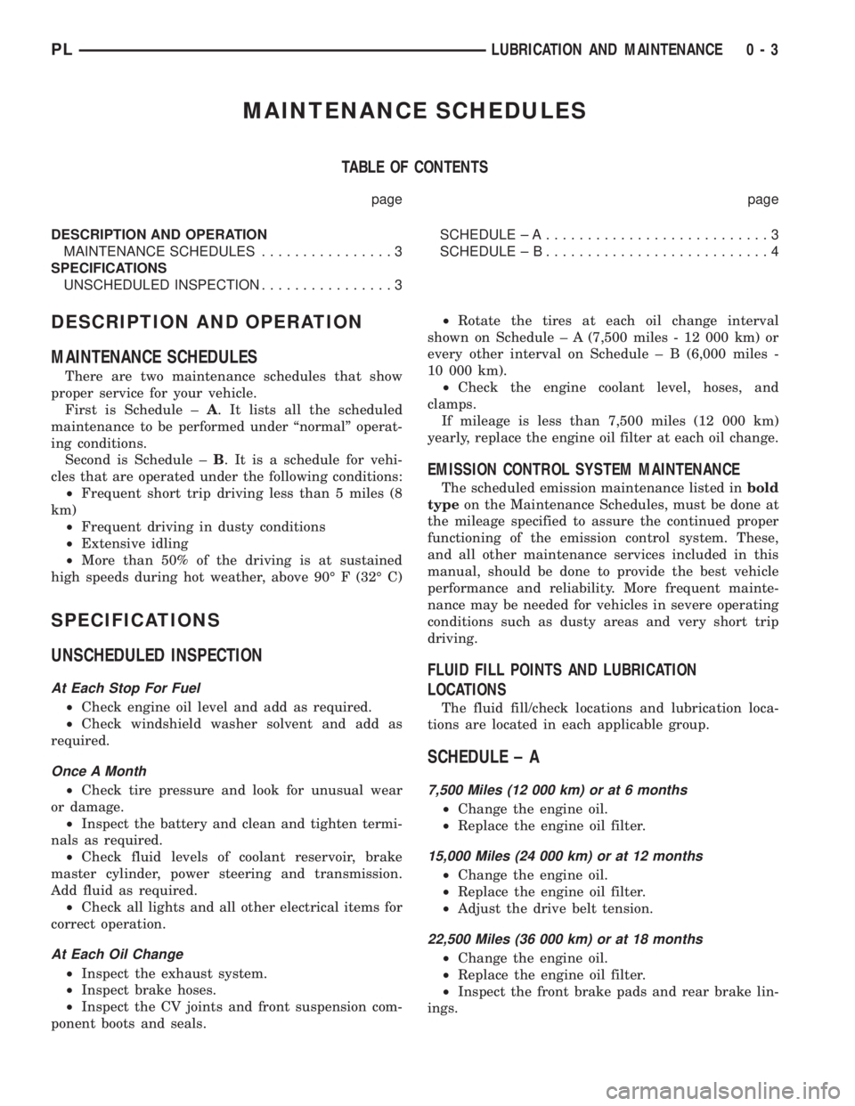
MAINTENANCE SCHEDULES
TABLE OF CONTENTS
page page
DESCRIPTION AND OPERATION
MAINTENANCE SCHEDULES................3
SPECIFICATIONS
UNSCHEDULED INSPECTION................3SCHEDULE ± A...........................3
SCHEDULE ± B...........................4
DESCRIPTION AND OPERATION
MAINTENANCE SCHEDULES
There are two maintenance schedules that show
proper service for your vehicle.
First is Schedule ±A. It lists all the scheduled
maintenance to be performed under ªnormalº operat-
ing conditions.
Second is Schedule ±B. It is a schedule for vehi-
cles that are operated under the following conditions:
²Frequent short trip driving less than 5 miles (8
km)
²Frequent driving in dusty conditions
²Extensive idling
²More than 50% of the driving is at sustained
high speeds during hot weather, above 90É F (32É C)
SPECIFICATIONS
UNSCHEDULED INSPECTION
At Each Stop For Fuel
²Check engine oil level and add as required.
²Check windshield washer solvent and add as
required.
Once A Month
²Check tire pressure and look for unusual wear
or damage.
²Inspect the battery and clean and tighten termi-
nals as required.
²Check fluid levels of coolant reservoir, brake
master cylinder, power steering and transmission.
Add fluid as required.
²Check all lights and all other electrical items for
correct operation.
At Each Oil Change
²Inspect the exhaust system.
²Inspect brake hoses.
²Inspect the CV joints and front suspension com-
ponent boots and seals.²Rotate the tires at each oil change interval
shown on Schedule ± A (7,500 miles - 12 000 km) or
every other interval on Schedule ± B (6,000 miles -
10 000 km).
²Check the engine coolant level, hoses, and
clamps.
If mileage is less than 7,500 miles (12 000 km)
yearly, replace the engine oil filter at each oil change.
EMISSION CONTROL SYSTEM MAINTENANCE
The scheduled emission maintenance listed inbold
typeon the Maintenance Schedules, must be done at
the mileage specified to assure the continued proper
functioning of the emission control system. These,
and all other maintenance services included in this
manual, should be done to provide the best vehicle
performance and reliability. More frequent mainte-
nance may be needed for vehicles in severe operating
conditions such as dusty areas and very short trip
driving.
FLUID FILL POINTS AND LUBRICATION
LOCATIONS
The fluid fill/check locations and lubrication loca-
tions are located in each applicable group.
SCHEDULE ± A
7,500 Miles (12 000 km) or at 6 months
²Change the engine oil.
²Replace the engine oil filter.
15,000 Miles (24 000 km) or at 12 months
²Change the engine oil.
²Replace the engine oil filter.
²Adjust the drive belt tension.
22,500 Miles (36 000 km) or at 18 months
²Change the engine oil.
²Replace the engine oil filter.
²Inspect the front brake pads and rear brake lin-
ings.
PLLUBRICATION AND MAINTENANCE 0 - 3
Page 90 of 1285
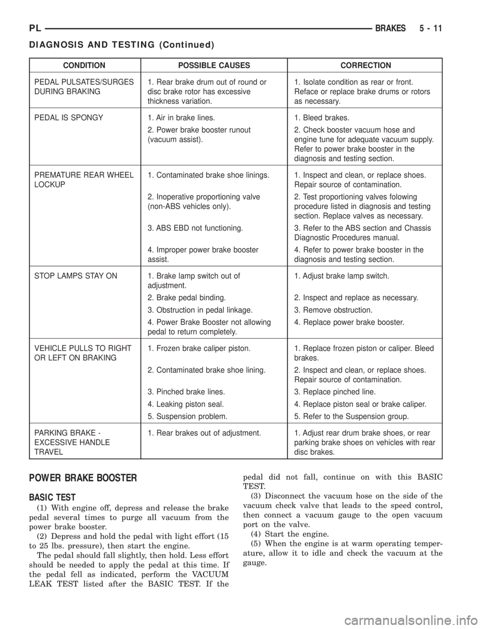
CONDITION POSSIBLE CAUSES CORRECTION
PEDAL PULSATES/SURGES
DURING BRAKING1. Rear brake drum out of round or
disc brake rotor has excessive
thickness variation.1. Isolate condition as rear or front.
Reface or replace brake drums or rotors
as necessary.
PEDAL IS SPONGY 1. Air in brake lines. 1. Bleed brakes.
2. Power brake booster runout
(vacuum assist).2. Check booster vacuum hose and
engine tune for adequate vacuum supply.
Refer to power brake booster in the
diagnosis and testing section.
PREMATURE REAR WHEEL
LOCKUP1. Contaminated brake shoe linings. 1. Inspect and clean, or replace shoes.
Repair source of contamination.
2. Inoperative proportioning valve
(non-ABS vehicles only).2. Test proportioning valves folowing
procedure listed in diagnosis and testing
section. Replace valves as necessary.
3. ABS EBD not functioning. 3. Refer to the ABS section and Chassis
Diagnostic Procedures manual.
4. Improper power brake booster
assist.4. Refer to power brake booster in the
diagnosis and testing section.
STOP LAMPS STAY ON 1. Brake lamp switch out of
adjustment.1. Adjust brake lamp switch.
2. Brake pedal binding. 2. Inspect and replace as necessary.
3. Obstruction in pedal linkage. 3. Remove obstruction.
4. Power Brake Booster not allowing
pedal to return completely.4. Replace power brake booster.
VEHICLE PULLS TO RIGHT
OR LEFT ON BRAKING1. Frozen brake caliper piston. 1. Replace frozen piston or caliper. Bleed
brakes.
2. Contaminated brake shoe lining. 2. Inspect and clean, or replace shoes.
Repair source of contamination.
3. Pinched brake lines. 3. Replace pinched line.
4. Leaking piston seal. 4. Replace piston seal or brake caliper.
5. Suspension problem. 5. Refer to the Suspension group.
PARKING BRAKE -
EXCESSIVE HANDLE
TRAVEL1. Rear brakes out of adjustment. 1. Adjust rear drum brake shoes, or rear
parking brake shoes on vehicles with rear
disc brakes.
POWER BRAKE BOOSTER
BASIC TEST
(1) With engine off, depress and release the brake
pedal several times to purge all vacuum from the
power brake booster.
(2) Depress and hold the pedal with light effort (15
to 25 lbs. pressure), then start the engine.
The pedal should fall slightly, then hold. Less effort
should be needed to apply the pedal at this time. If
the pedal fell as indicated, perform the VACUUM
LEAK TEST listed after the BASIC TEST. If thepedal did not fall, continue on with this BASIC
TEST.
(3) Disconnect the vacuum hose on the side of the
vacuum check valve that leads to the speed control,
then connect a vacuum gauge to the open vacuum
port on the valve.
(4) Start the engine.
(5) When the engine is at warm operating temper-
ature, allow it to idle and check the vacuum at the
gauge.
PLBRAKES 5 - 11
DIAGNOSIS AND TESTING (Continued)
Page 91 of 1285
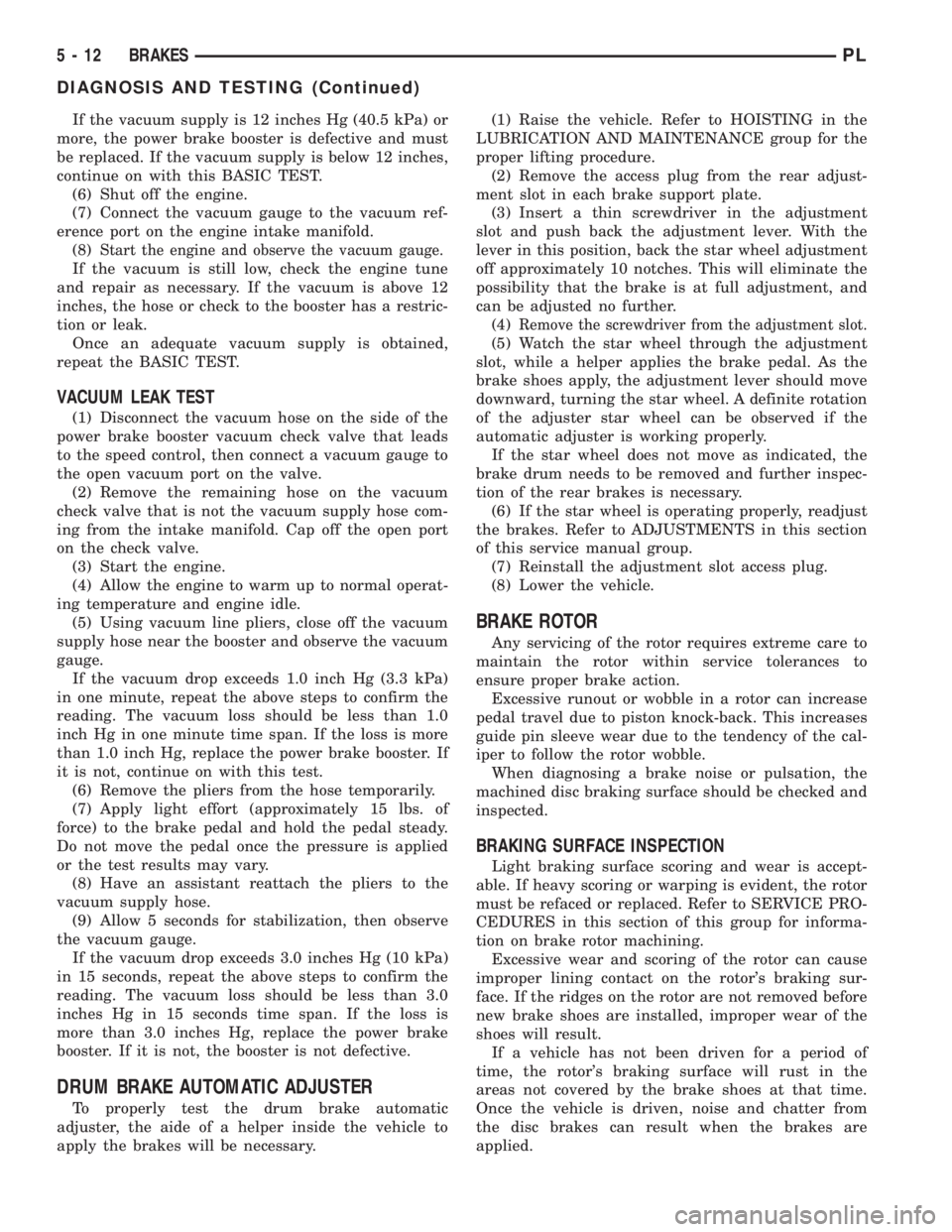
If the vacuum supply is 12 inches Hg (40.5 kPa) or
more, the power brake booster is defective and must
be replaced. If the vacuum supply is below 12 inches,
continue on with this BASIC TEST.
(6) Shut off the engine.
(7) Connect the vacuum gauge to the vacuum ref-
erence port on the engine intake manifold.
(8)
Start the engine and observe the vacuum gauge.
If the vacuum is still low, check the engine tune
and repair as necessary. If the vacuum is above 12
inches, the hose or check to the booster has a restric-
tion or leak.
Once an adequate vacuum supply is obtained,
repeat the BASIC TEST.
VACUUM LEAK TEST
(1) Disconnect the vacuum hose on the side of the
power brake booster vacuum check valve that leads
to the speed control, then connect a vacuum gauge to
the open vacuum port on the valve.
(2) Remove the remaining hose on the vacuum
check valve that is not the vacuum supply hose com-
ing from the intake manifold. Cap off the open port
on the check valve.
(3) Start the engine.
(4) Allow the engine to warm up to normal operat-
ing temperature and engine idle.
(5) Using vacuum line pliers, close off the vacuum
supply hose near the booster and observe the vacuum
gauge.
If the vacuum drop exceeds 1.0 inch Hg (3.3 kPa)
in one minute, repeat the above steps to confirm the
reading. The vacuum loss should be less than 1.0
inch Hg in one minute time span. If the loss is more
than 1.0 inch Hg, replace the power brake booster. If
it is not, continue on with this test.
(6) Remove the pliers from the hose temporarily.
(7) Apply light effort (approximately 15 lbs. of
force) to the brake pedal and hold the pedal steady.
Do not move the pedal once the pressure is applied
or the test results may vary.
(8) Have an assistant reattach the pliers to the
vacuum supply hose.
(9) Allow 5 seconds for stabilization, then observe
the vacuum gauge.
If the vacuum drop exceeds 3.0 inches Hg (10 kPa)
in 15 seconds, repeat the above steps to confirm the
reading. The vacuum loss should be less than 3.0
inches Hg in 15 seconds time span. If the loss is
more than 3.0 inches Hg, replace the power brake
booster. If it is not, the booster is not defective.
DRUM BRAKE AUTOMATIC ADJUSTER
To properly test the drum brake automatic
adjuster, the aide of a helper inside the vehicle to
apply the brakes will be necessary.(1) Raise the vehicle. Refer to HOISTING in the
LUBRICATION AND MAINTENANCE group for the
proper lifting procedure.
(2) Remove the access plug from the rear adjust-
ment slot in each brake support plate.
(3) Insert a thin screwdriver in the adjustment
slot and push back the adjustment lever. With the
lever in this position, back the star wheel adjustment
off approximately 10 notches. This will eliminate the
possibility that the brake is at full adjustment, and
can be adjusted no further.
(4)
Remove the screwdriver from the adjustment slot.
(5) Watch the star wheel through the adjustment
slot, while a helper applies the brake pedal. As the
brake shoes apply, the adjustment lever should move
downward, turning the star wheel. A definite rotation
of the adjuster star wheel can be observed if the
automatic adjuster is working properly.
If the star wheel does not move as indicated, the
brake drum needs to be removed and further inspec-
tion of the rear brakes is necessary.
(6) If the star wheel is operating properly, readjust
the brakes. Refer to ADJUSTMENTS in this section
of this service manual group.
(7) Reinstall the adjustment slot access plug.
(8) Lower the vehicle.
BRAKE ROTOR
Any servicing of the rotor requires extreme care to
maintain the rotor within service tolerances to
ensure proper brake action.
Excessive runout or wobble in a rotor can increase
pedal travel due to piston knock-back. This increases
guide pin sleeve wear due to the tendency of the cal-
iper to follow the rotor wobble.
When diagnosing a brake noise or pulsation, the
machined disc braking surface should be checked and
inspected.
BRAKING SURFACE INSPECTION
Light braking surface scoring and wear is accept-
able. If heavy scoring or warping is evident, the rotor
must be refaced or replaced. Refer to SERVICE PRO-
CEDURES in this section of this group for informa-
tion on brake rotor machining.
Excessive wear and scoring of the rotor can cause
improper lining contact on the rotor's braking sur-
face. If the ridges on the rotor are not removed before
new brake shoes are installed, improper wear of the
shoes will result.
If a vehicle has not been driven for a period of
time, the rotor's braking surface will rust in the
areas not covered by the brake shoes at that time.
Once the vehicle is driven, noise and chatter from
the disc brakes can result when the brakes are
applied.
5 - 12 BRAKESPL
DIAGNOSIS AND TESTING (Continued)
Page 168 of 1285
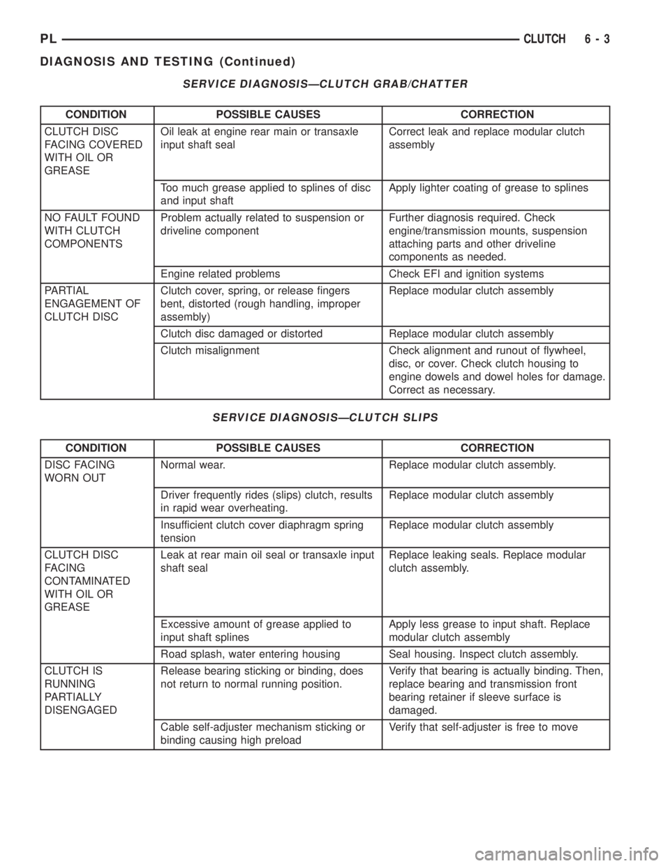
SERVICE DIAGNOSISÐCLUTCH GRAB/CHATTER
CONDITION POSSIBLE CAUSES CORRECTION
CLUTCH DISC
FACING COVERED
WITH OIL OR
GREASEOil leak at engine rear main or transaxle
input shaft sealCorrect leak and replace modular clutch
assembly
Too much grease applied to splines of disc
and input shaftApply lighter coating of grease to splines
NO FAULT FOUND
WITH CLUTCH
COMPONENTSProblem actually related to suspension or
driveline componentFurther diagnosis required. Check
engine/transmission mounts, suspension
attaching parts and other driveline
components as needed.
Engine related problems Check EFI and ignition systems
PARTIAL
ENGAGEMENT OF
CLUTCH DISCClutch cover, spring, or release fingers
bent, distorted (rough handling, improper
assembly)Replace modular clutch assembly
Clutch disc damaged or distorted Replace modular clutch assembly
Clutch misalignment Check alignment and runout of flywheel,
disc, or cover. Check clutch housing to
engine dowels and dowel holes for damage.
Correct as necessary.
SERVICE DIAGNOSISÐCLUTCH SLIPS
CONDITION POSSIBLE CAUSES CORRECTION
DISC FACING
WORN OUTNormal wear. Replace modular clutch assembly.
Driver frequently rides (slips) clutch, results
in rapid wear overheating.Replace modular clutch assembly
Insufficient clutch cover diaphragm spring
tensionReplace modular clutch assembly
CLUTCH DISC
FACING
CONTAMINATED
WITH OIL OR
GREASELeak at rear main oil seal or transaxle input
shaft sealReplace leaking seals. Replace modular
clutch assembly.
Excessive amount of grease applied to
input shaft splinesApply less grease to input shaft. Replace
modular clutch assembly
Road splash, water entering housing Seal housing. Inspect clutch assembly.
CLUTCH IS
RUNNING
PARTIALLY
DISENGAGEDRelease bearing sticking or binding, does
not return to normal running position.Verify that bearing is actually binding. Then,
replace bearing and transmission front
bearing retainer if sleeve surface is
damaged.
Cable self-adjuster mechanism sticking or
binding causing high preloadVerify that self-adjuster is free to move
PLCLUTCH 6 - 3
DIAGNOSIS AND TESTING (Continued)
Page 170 of 1285
DRIVE PLATE MISALIGNMENT
Common causes of misalignment are:
²Heat warping
²Mounting drive plate on a dirty crankshaft
flange
²Incorrect bolt tightening
²Improper seating on the crankshaft shoulder
²Loose crankshaft bolts
Clean the crankshaft flange before mounting the
drive plate. Dirt and grease on the flange surface
may misalign the flywheel, causing excessive runout.
Use new bolts when mounting drive plate to crank-
shaft. Tighten drive plate bolts to specified torque
only. Over-tightening can distort the drive plate hub
causing excessive runout.
CLUTCH CHATTER COMPLAINTS
For all clutch chatter complaints, do the following:
(1) Check for loose, misaligned, or broken engine
and transmission mounts. If present, they should be
corrected at this time. Test vehicle for chatter. If
chatter is gone, there is no need to go any further. If
chatter persists:
(2) Check to see if clutch cable routing is correct
and operates smoothly.
(3) Check for loose connections in drive train. Cor-
rect any problems and determine if clutch chatter
complaints have been satisfied. If not:
(4) Remove transaxle. See Group 21, Manual Tran-
saxle for procedure.
(5) Check to see if the release bearing is sticky or
binding. Replace bearing, if needed.
(6) Check linkage for excessive wear on the pivot
stud and fork fingers. Replace all worn parts.
(7) Check clutch assembly for contamination (dirt,
oil). Replace clutch assembly, if required.
(8) Check to see if the clutch disc hub splines are
damaged. Replace with new clutch assembly, if nec-
essary.
(9) Check input shaft splines for damage. Replace,
if necessary.
(10) Check for uneven wear on clutch fingers.
(11) Check for broken clutch cover diaphragm
spring fingers. Replace with new clutch assembly, if
necessary.
CLASH±INTO±REVERSE COMPLAINTS
Certain NV T350 (A-578) manual transaxles are
equipped with a reverse brake. It prevents clash
when shifting into reverse, but only if the vehicle is
not moving. See Group 21, Transaxle for further
diagnosis.
(1) Depress clutch pedal to floor and hold. After
three seconds, shift to reverse. If clash is present,
clutch has excessive spin time, and the reverse brake
may not be functioning.(2) Remove transaxle. See Group 21, Manual Tran-
saxle for procedure.
(3) Check the input shaft spline, clutch disc
splines, and release bearing for dry rust. If present,
clean rust off and apply a light coat of bearing grease
to the input shaft splines. Apply grease on the input
shaft splines only where the clutch disc slides. Verify
that the clutch disc slides freely along the input shaft
spline.
(4) Check to see if the clutch disc hub splines are
damaged, and replace with new clutch assembly if
required.
(5) Check the input shaft for damaged splines.
Replace as necessary.
(6) Check for broken clutch cover diaphragm
spring fingers.
(7) Install clutch assembly and transaxle.
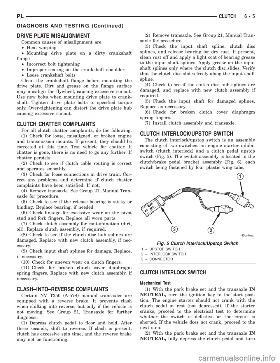
CLUTCH INTERLOCK/UPSTOP SWITCH
The clutch interlock/upstop switch is an assembly
consisting of two switches: an engine starter inhibit
switch (clutch interlock) and a clutch pedal upstop
switch (Fig. 5). The switch assembly is located in the
clutch/brake pedal bracket assembly (Fig. 6), each
switch being fastened by four plastic wing tabs.
CLUTCH INTERLOCK SWITCH
Mechanical Test
(1) With the park brake set and the transaxleIN
NEUTRAL,turn the ignition key to the start posi-
tion. The engine starter should not crank with the
clutch pedal at rest (not depressed). If the starter
cranks, proceed to the electrical test to determine
whether the switch is defective or the circuit is
shorted. If the vehicle does not crank, proceed to the
next step.
(2) With the park brake set and the transaxleIN
NEUTRAL,fully depress the clutch pedal and turn
Fig. 5 Clutch Interlock/Upstop Switch
1 ± UPSTOP SWITCH
2 ± INTERLOCK SWITCH
3 ± CONNECTOR
PLCLUTCH 6 - 5
DIAGNOSIS AND TESTING (Continued)
Page 172 of 1285
SERVICE DIAGNOSIS±CLUTCH INTERLOCK/UPSTOP SWITCH
CONDITION POSSIBLE CAUSES CORRECTION
ENGINE STARTER
WON'T CRANK
WHEN CLUTCH
PEDAL IS
PRESSED TO THE
FLOORClutch interlock switch does not have
continuity when plunger is depressed 1.25
mm (1.30 in.)Defective switch or open wiring circuit.
Replace switch if necessary.
Interlock switch plunger is not depressed
when clutch pedal is pushed to the floorFloor mat interferes with clutch pedal
movement or clutch pedal bracket is bent.
Problem is related to other components in
the starting circuit.Check other components in the starting
circuit. Refer to Battery/Starting/Charging
System in Group 8.
SPEED CONTROL
DOES NOT
TERMINATE WHEN
CLUTCH PEDAL IS
DEPRESSED BY AT
LEAST 33 mm (1.30
in.)Upstop switch circuit is closed when clutch
pedal is depressed, or harness is shorted.Refer to Upstop Switch Electrical Test in
this group. Repair wiring or replace switch
assembly as necessary.
Other speed control system failure. Refer to Group 8H, Speed Control for
further diagnosis and testing procedures.
REMOVAL AND INSTALLATION
CLUTCH CABLE
REMOVAL
(1) Disconnect both battery cables.
(2) Remove battery clamp and remove battery
from vehicle.
(3) Remove battery tray from mount bracket.
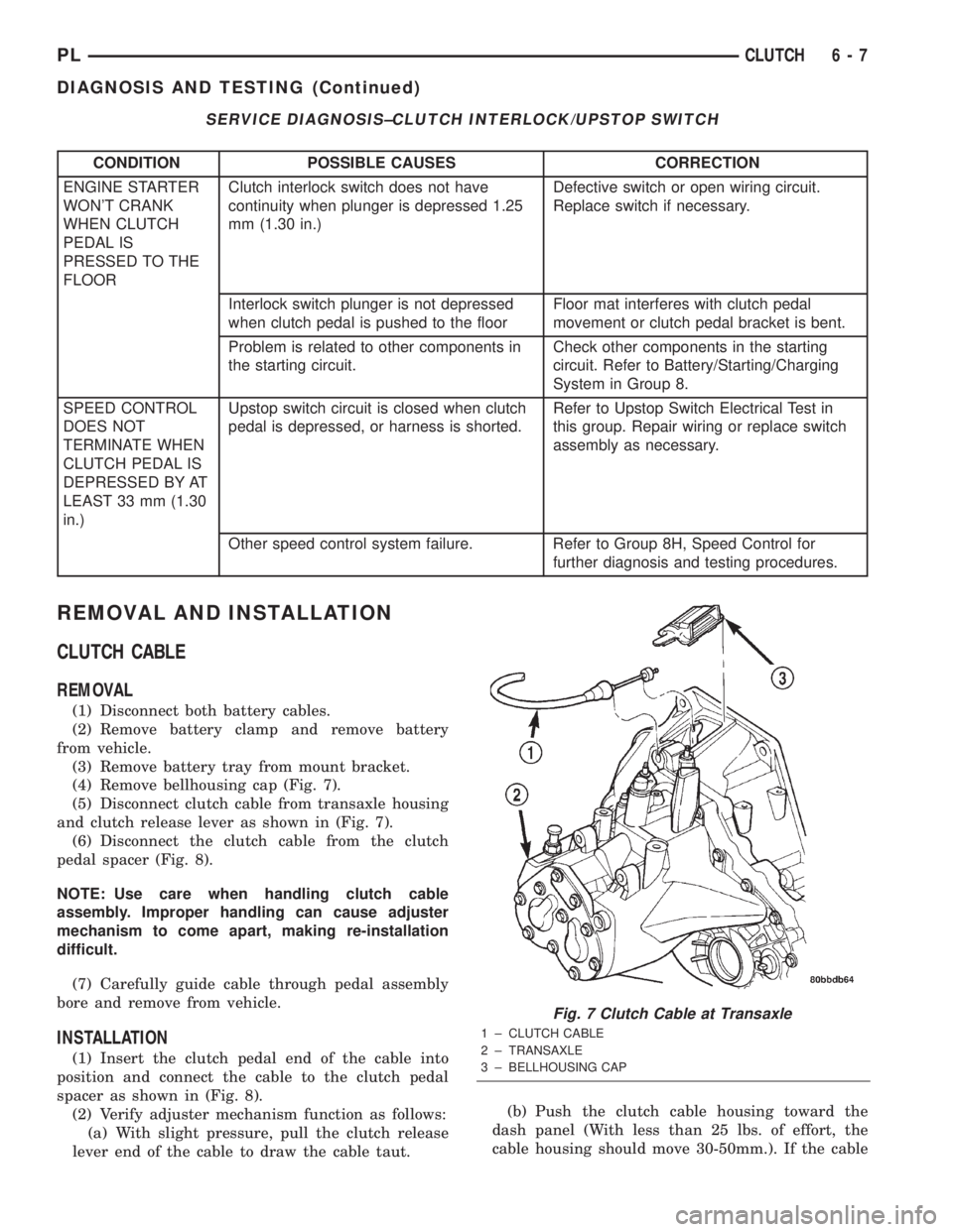
(4) Remove bellhousing cap (Fig. 7).
(5) Disconnect clutch cable from transaxle housing
and clutch release lever as shown in (Fig. 7).
(6) Disconnect the clutch cable from the clutch
pedal spacer (Fig. 8).
NOTE: Use care when handling clutch cable
assembly. Improper handling can cause adjuster
mechanism to come apart, making re-installation
difficult.
(7) Carefully guide cable through pedal assembly
bore and remove from vehicle.
INSTALLATION
(1) Insert the clutch pedal end of the cable into
position and connect the cable to the clutch pedal
spacer as shown in (Fig. 8).
(2) Verify adjuster mechanism function as follows:
(a) With slight pressure, pull the clutch release
lever end of the cable to draw the cable taut.(b) Push the clutch cable housing toward the
dash panel (With less than 25 lbs. of effort, the
cable housing should move 30-50mm.). If the cable
Fig. 7 Clutch Cable at Transaxle
1 ± CLUTCH CABLE
2 ± TRANSAXLE
3 ± BELLHOUSING CAP
PLCLUTCH 6 - 7
DIAGNOSIS AND TESTING (Continued)
Page 188 of 1285
CONDITION POSSIBLE CAUSE CORRECTION
16. Electric cooling fan not
operating properly.16. Check electric fan operation and
repair as necessary.
17. Cylinder head gasket leaking. 17. Check cylinder head gasket for
leaks. Refer to testing cooling
system for leaks. For repairs, refer
to Group 9, Engine.
18. Heater core leaking. 18. Check heater core for leaks.
Refer to Group 24, Heating and Air
Conditioning and repair as
necessary.
TEMPERATURE GAUGE READING
IS INCONSISTENT (FLUCTUATES,
CYCLES OR IS ERRATIC)1. The gauge may cycle up and
down. This is due to the cycling of
the electric radiator fan.1. A normal condition. No correction
is necessary. If gauge cycling is
going into the hot zone, check
electric fan operation and repair as
necessary. Refer to procedure in
this section.
2. During cold weather operation
with the heater blower in the high
position, the gauge reading may
drop slightly.2. A normal condition. No correction
is necessary.
3, Temperature gauge or engine
mounted gauge sensor is defective
or shorted.3. Check operation of gauge and
repair as necessary. Refer to Group
8E, Instrument Panel and Gauges.
4. Gauge reading rises when
vehicle is brought to a stop after
heavy use (engine still running).4. A normal condition. No correction
is necessary. The gauge should
return to normal range after vehicle
is driven.
5. Gauge reading high after
restarting a warmed-up (hot)
engine.5. A normal condition. No correction
is necessary. The gauge should
return to normal range after a few
minutes of engine operation.
6. Coolant level low in radiator (air
will build up in the cooling system
causing the thermostat to open
late).6. Check and correct coolant leaks.
Refer to Testing Cooling System For
Leaks in the section.
7. Cylinder head gasket leaking
allowing exhaust gas to enter
cooling system. This will cause
thermostat to open late.7. (a) Check for cylinder head
gasket leaks with a commercially
available Block Leak Tester. Repair
as necessary.
(b) Check for coolant in the engine
oil. Inspect for white steam emitting
from exhaust system. Repair as
necessary.
8. Water pump impeller loose on
shaft.8. Check water pump and replace
as necessary. Refer to Water Pump
in this section.
9. Loose drive belt (water pump
slipping).9. Check drive belt and correct as
necessary.
PLCOOLING SYSTEM 7 - 9
DIAGNOSIS AND TESTING (Continued)
Page 193 of 1285
ENGINE THERMOSTAT TESTING
The thermostat is operated by a wax filled con-
tainer (pellet) which is sealed. When heated coolant
reaches a predetermined temperature the wax pellet
expands enough to overcome the closing spring and
water pump pressure, which forces the valve to open.
Coolant leakage into the pellet will cause a thermo-
stat to fail open. Do not attempt to free up a thermo-
stat with a screwdriver.
The thermostat that opens too soon type failure
mode is included in the on-board diagnosis. Thecheck engine light will not be lit by an open too soon
condition. If it has failed open, a diagnostic trouble
code (DTC) will be set. Do not change a thermostat
for lack of heater performance or temperature gauge
position, unless a DTC is present. See Diagnosis for
other probable causes. Thermostat failing shut is the
normal long term mode of failure, and normally, only
on high mileage vehicles. The temperature gauge will
indicate this. Refer to Diagnosis in this section.
ACCESSORY DRIVE BELT DIAGNOSIS
CONDITION POSSIBLE CAUSE CORRECTION
BELT SLIPPAGE 1. Belt slipping because of
insufficient tension.1. Retension generator belt.
Replace the power steering belt's
automatic belt tensioner.
2. Belt excessively glazed or
hardened from heat and excessive
slippage.2. Replace belt.
3. Incorrect belt. 3. Replace belt.
4. Driven component bearing
failure.4. Replace faulty component.
5. Belt or pulley subjected to
substance (belt dressing, oil,
ethylene glycol) that has reduced
friction.5. Replace belt and clean pulleys.
BELT NOISE (OBJECTIONABLE
SQUEAL, SQUEAK, OR RUMBLE)1. Belt slippage. 1. Retension generator belt, replace
belt, or automatic belt tensioner.
2. Foreign material imbedded in
belt.2. Replace belt.
3. Non-uniform belt. 3. Replace belt.
4. Misaligned pulley(s). 4. Align accessories.
5. Non-uniform groove or eccentric
pulley.5. Replace pulley(s).
6. Bearing noise. 6. Locate and repair.
BELT ROLLED OVER IN GROOVE
OR BELT JUMPS OFF1. Broken cord in belt. 1. Replace belt.
2. Belt tension too loose, or too
tight.2. Retension generator belt.
Replace the power steering belt's
automatic belt tensioner.
3. Misaligned pulleys. 3. Align accessories.
4. Non-uniform grooves or eccentric
pulley.4. Replace pulley(s).
5. Foreign object(s) in grooves. 5. Remove foreign objects in
groove.
7 - 14 COOLING SYSTEMPL
DIAGNOSIS AND TESTING (Continued)