2000 DODGE NEON airbag
[x] Cancel search: airbagPage 154 of 1285
ABS ELECTRONIC DIAGNOSIS
The following information is presented to give the
technician a general background on the diagnostic
capabilities of the ABS system. Complete electronic
diagnosis of the ABS system used on this vehicle is
covered in the Chassis Diagnostic Procedures manual.
Electronic diagnosis of the ABS system used on
this vehicle is performed using the DRBIIItscan
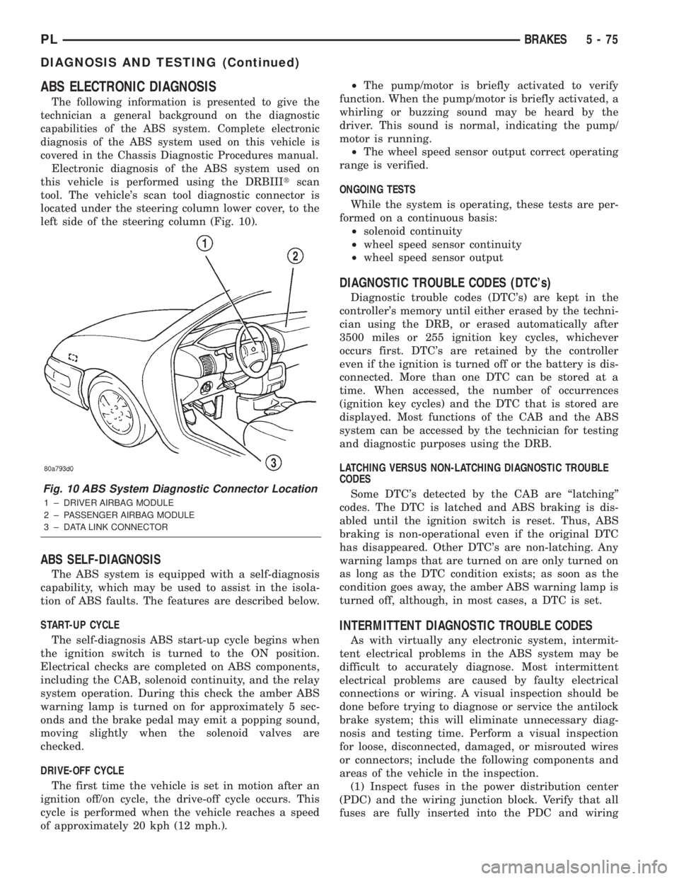
tool. The vehicle's scan tool diagnostic connector is
located under the steering column lower cover, to the
left side of the steering column (Fig. 10).
ABS SELF-DIAGNOSIS
The ABS system is equipped with a self-diagnosis
capability, which may be used to assist in the isola-
tion of ABS faults. The features are described below.
START-UP CYCLE
The self-diagnosis ABS start-up cycle begins when
the ignition switch is turned to the ON position.
Electrical checks are completed on ABS components,
including the CAB, solenoid continuity, and the relay
system operation. During this check the amber ABS
warning lamp is turned on for approximately 5 sec-
onds and the brake pedal may emit a popping sound,
moving slightly when the solenoid valves are
checked.
DRIVE-OFF CYCLE
The first time the vehicle is set in motion after an
ignition off/on cycle, the drive-off cycle occurs. This
cycle is performed when the vehicle reaches a speed
of approximately 20 kph (12 mph.).²The pump/motor is briefly activated to verify
function. When the pump/motor is briefly activated, a
whirling or buzzing sound may be heard by the
driver. This sound is normal, indicating the pump/
motor is running.
²The wheel speed sensor output correct operating
range is verified.
ONGOING TESTS
While the system is operating, these tests are per-
formed on a continuous basis:
²solenoid continuity
²wheel speed sensor continuity
²wheel speed sensor output
DIAGNOSTIC TROUBLE CODES (DTC's)
Diagnostic trouble codes (DTC's) are kept in the
controller's memory until either erased by the techni-
cian using the DRB, or erased automatically after
3500 miles or 255 ignition key cycles, whichever
occurs first. DTC's are retained by the controller
even if the ignition is turned off or the battery is dis-
connected. More than one DTC can be stored at a
time. When accessed, the number of occurrences
(ignition key cycles) and the DTC that is stored are
displayed. Most functions of the CAB and the ABS
system can be accessed by the technician for testing
and diagnostic purposes using the DRB.
LATCHING VERSUS NON-LATCHING DIAGNOSTIC TROUBLE
CODES
Some DTC's detected by the CAB are ªlatchingº
codes. The DTC is latched and ABS braking is dis-
abled until the ignition switch is reset. Thus, ABS
braking is non-operational even if the original DTC
has disappeared. Other DTC's are non-latching. Any
warning lamps that are turned on are only turned on
as long as the DTC condition exists; as soon as the
condition goes away, the amber ABS warning lamp is
turned off, although, in most cases, a DTC is set.
INTERMITTENT DIAGNOSTIC TROUBLE CODES
As with virtually any electronic system, intermit-
tent electrical problems in the ABS system may be
difficult to accurately diagnose. Most intermittent
electrical problems are caused by faulty electrical
connections or wiring. A visual inspection should be
done before trying to diagnose or service the antilock
brake system; this will eliminate unnecessary diag-
nosis and testing time. Perform a visual inspection
for loose, disconnected, damaged, or misrouted wires
or connectors; include the following components and
areas of the vehicle in the inspection.
(1) Inspect fuses in the power distribution center
(PDC) and the wiring junction block. Verify that all
fuses are fully inserted into the PDC and wiring
Fig. 10 ABS System Diagnostic Connector Location
1 ± DRIVER AIRBAG MODULE
2 ± PASSENGER AIRBAG MODULE
3 ± DATA LINK CONNECTOR
PLBRAKES 5 - 75
DIAGNOSIS AND TESTING (Continued)
Page 240 of 1285
KNOCK SENSOR
DESCRIPTION
The knock sensor threads into the cylinder block.
OPERATION
When the knock sensor detects a knock in one of
the cylinders, it sends an input signal to the PCM. In
response, the PCM retards ignition timing for all cyl-
inders by a scheduled amount.Knock sensors contain a piezoelectric material
which constantly vibrates and sends an input voltage
(signal) to the PCM while the engine operates. As the
intensity of the crystal's vibration increases, the
knock sensor output voltage also increases.
NOTE: Over or under tightening affects knock sen-
sor performance, possibly causing improper spark
control.
IGNITION SWITCH
In the RUN position, the ignition switch connects
power from the Power Distribution Center (PDC) to a
fuse in the fuse block, back to a bus bar in the PDC.
The bus bar feeds circuits for the Powertrain Control
Module (PCM), Proportional purge solenoid, EGR
solenoid, and ABS system. The bus bar in the PDC
feeds the coil side of the radiator fan relay, A/C com-
pressor clutch relay, and the fuel pump relay. It also
feeds the Airbag Control Module (ACM)
LOCK KEY CYLINDER
DESCRIPTION
The lock cylinder is inserted in the end of the
housing opposite the ignition switch.
OPERATION
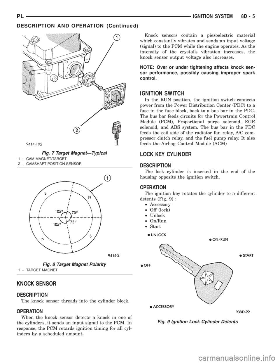
The ignition key rotates the cylinder to 5 different
detents (Fig. 9) :
²Accessory
²Off (lock)
²Unlock
²On/Run
²Start
Fig. 7 Target MagnetÐTypical
1 ± CAM MAGNET/TARGET
2 ± CAMSHAFT POSITION SENSOR
Fig. 8 Target Magnet Polarity
1 ± TARGET MAGNET
Fig. 9 Ignition Lock Cylinder Detents
PLIGNITION SYSTEM 8D - 5
DESCRIPTION AND OPERATION (Continued)
Page 248 of 1285
INSTRUMENT PANEL SYSTEMS
TABLE OF CONTENTS
page page
GENERAL INFORMATION
INTRODUCTION..........................1
DESCRIPTION AND OPERATION
HEADLAMP SWITCH......................2
INSTRUMENT CLUSTER....................2
WARNING AND INDICATOR LAMPS..........2
DIAGNOSIS AND TESTING
AIRBAG WARNING SYSTEM................2
BRAKE SYSTEM WARNING LAMP TEST.......2
INSTRUMENT CLUSTER LAMPS.............2
LOW OIL PRESSURE WARNING LAMP TEST...3
MULTIPLE/INDIVIDUAL GAUGES
INOPERATIVE..........................4
SERVICE PROCEDURES
INSTRUMENT CLUSTER SELF-DIAGNOSTICS...4
REMOVAL AND INSTALLATION
ACCESSORY SWITCH/POWER OUTLET
BEZEL................................4CENTER CONSOLE FLOOD LAMP............5
CIGAR LIGHTER / POWER OUTLET
ASSEMBLY.............................5
GLOVE BOX DOOR/BIN....................6
GLOVE BOX DOOR/BIN....................6
GLOVE BOX SWITCH/LAMP.................6
INSTRUMENT CLUSTER....................6
INSTRUMENT CLUSTER BEZEL..............6
INSTRUMENT CLUSTER LAMPS.............7
INSTRUMENT PANEL ASSEMBLY............7
INSTRUMENT PANEL CENTER BEZEL........10
INSTRUMENT PANEL END CAPS............10
INSTRUMENT PANEL TOP COVER...........10
LOWER INSTRUMENT PANEL COVER........10
LOWER STORAGE BIN....................10
STEERING COLUMN SHROUDS.............11
GENERAL INFORMATION
INTRODUCTION
The purpose of the dash gauges and indicator
lamps is to keep the driver informed about the oper-
ating condition of the vehicle. If an abnormal condi-
tion occurs, the driver is informed by indicator lamp.
The driver can seek service before damage occurs.
Indicator lamps use ON/OFF switch functions for
operation, while gauges use a sending unit or sensor.
The Instrument Panel can be removed as an
assembly after a few part are removed to allow
access to the retaining bolts. There is one self-align-
ing bulkhead connector on the left underside of the
instrument panel replacing most of the main harness
connectors. Once removed, the instrument panel can
be serviced for replacement. Most of the parts of the
instrument panel can be replaced individually with-
out removing the complete instrument panel assem-
bly.
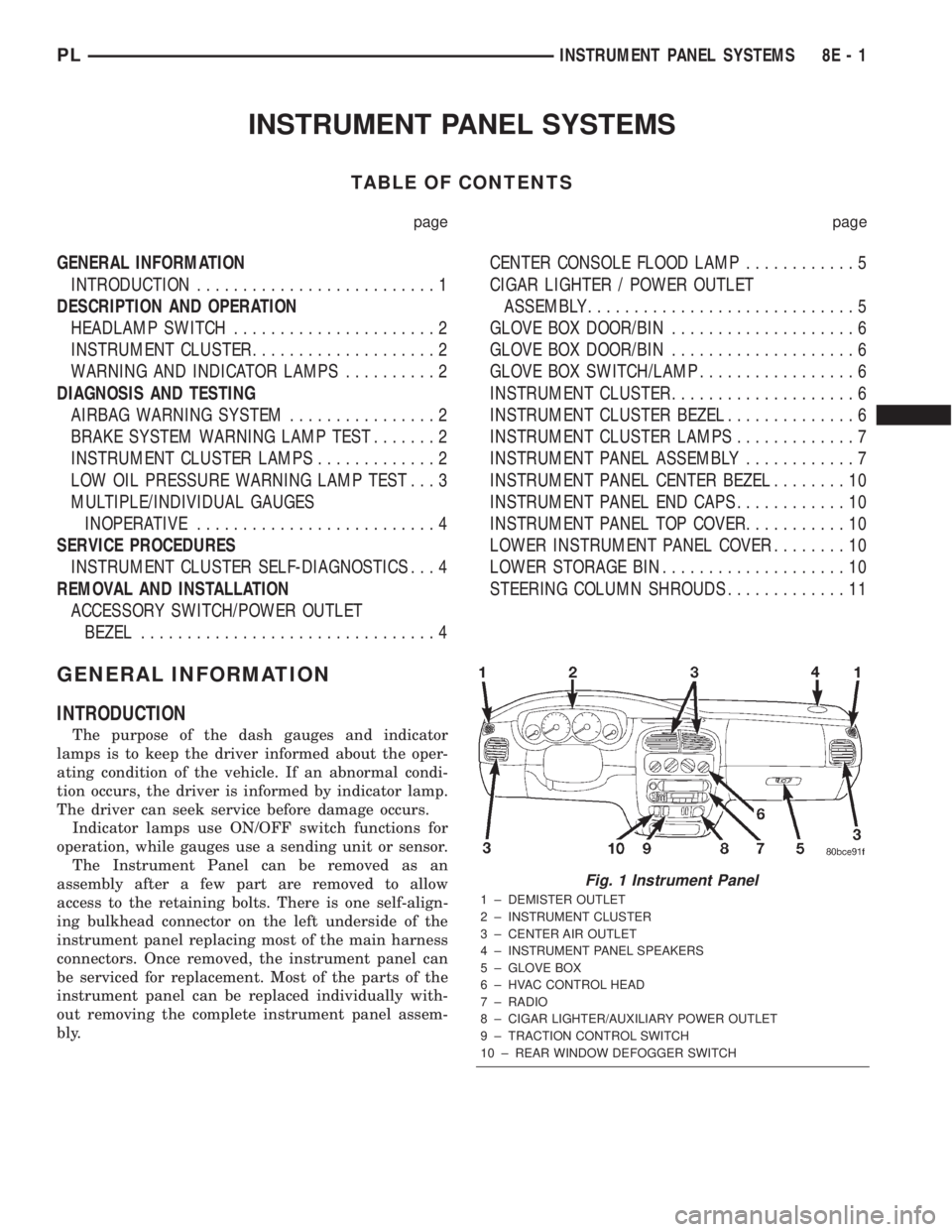
Fig. 1 Instrument Panel
1 ± DEMISTER OUTLET
2 ± INSTRUMENT CLUSTER
3 ± CENTER AIR OUTLET
4 ± INSTRUMENT PANEL SPEAKERS
5 ± GLOVE BOX
6 ± HVAC CONTROL HEAD
7 ± RADIO
8 ± CIGAR LIGHTER/AUXILIARY POWER OUTLET
9 ± TRACTION CONTROL SWITCH
10 ± REAR WINDOW DEFOGGER SWITCH
PLINSTRUMENT PANEL SYSTEMS 8E - 1
Page 249 of 1285
DESCRIPTION AND OPERATION
HEADLAMP SWITCH
The headlamp switch is part of the Multi-Function
Switch. Refer to Group 8J, Turn Signal and Flasher
for the Multi-Function Switch Test, Removal and
Installation procedures.
INSTRUMENT CLUSTER
There are two conventional instrument cluster
assemblies available. The clusters electronically drive
the speedometer, odometer, gauges, and tachometer
(if equipped). Refer to (Fig. 2) and (Fig. 3).
The instrument cluster controls the courtesy
lamps, it receives and sends messages to other mod-
ules via the PCI bus circuit, it controls all the instru-
ment illumination and the chime is also an integral
part of the cluster. The front turn signals are wired
through the cluster and then go to the front lamps.
The reason being that the DRL module is built into
the cluster (if equipped).
All gauges in the electronic clusters are the analog
type gauges. When the ignition switch is moved to
the OFF position, the cluster drives each gauge to its
lowest position. The individual gauges are not servi-
cable and require complete replacement of the cluster
if one or more gauges are inoperable.
One button is used to switch the display from trip
to total mileage. Holding the button when the display
is in the trip mode will reset the trip mileage. This
button is also used to put the cluster in self-diagnos-
tic mode. Refer to Service Procedures, Cluster Self-
Diagnostics in this section. Most of the indicators will
come on briefly for a bulb heck when the ignition is
turned from OFF to ON. All of the LED's are replace-
able.
In the event that the instrument cluster looses
communication with all other modules on the PCI
bus, the cluster will display ªnobusº in the VF dis-
play. The VF display also displays ªDoorº, ªCruiseº,
ªTracº, and odometer trip or total.
If the cluster does not detect voltage on the cour-
tesy lamp circuit, the message ªFUSEº will alternate
with the odometer/trip odometer for 30 seconds after
the ignition is turned on and for 15 seconds after the
vehicle is first moved. The lack of voltage can be due
to the M1 Fused B(+) (IOD) fuse being open, a bad or
missing courtesy lamp bulb, or a circuit problem.
WARNING AND INDICATOR LAMPS
The instrument cluster has warning lamps and
indicators for the following systems:
²Airbag
²Anti-lock Brakes (ABS) if equipped
²Brake warning
²Charging System²Front fog lamps (if equipped)
²High beam indicator
²Low fuel (premium cluster only)
²Low oil pressure
²Malfunction indicator (service engine soon) lamp
²Right and left turn signals
²Seat belt warning
²Security system
²Trac-Off (ABS equipped vehicles only)
The instrument cluster has a Vacuum Fluorescent
(VF) display for the following systems:
²Cruise
²Door (ajar)
²Odometer
²Set (cruise)
²Trac
²Trip
DIAGNOSIS AND TESTING
AIRBAG WARNING SYSTEM
For testing of this system refer to Group 8M, Pas-
sive Restraint Systems.
BRAKE SYSTEM WARNING LAMP TEST
The brake warning lamp illuminates when the
parking brake is applied with ignition switch turned
to the ON position. The same lamp will also illumi-
nate if one of the two service brake systems fail the
when brake pedal is applied.
To test the system:
²As the ignition switch is turned to the start posi-
tion the lamp should light.
²Turn ignition switch to the ON position and
apply the parking brake. The lamp should light.
If lamp fails to light inspect for:
²A burned out lamp
²Loose, corroded or damaged socket
²A damaged circuit board
²A broken or disconnected wire at the switch
²Defective switch
To test the service brake warning system, refer to
Group 5, Brakes, Hydraulic System Control Valves.
INSTRUMENT CLUSTER LAMPS
Every time the vehicle is switched to the START/
RUN position, the cluster goes through a BULB
CHECK. This tests most of the indicator lamps and
Vacuum Fluorescent (VF) displays. If only one lamp
is out, remove the instrument cluster and replace the
defective bulb or Light Emitting Diode (LED). If
some or all of the lamps fail to light, refer to the
proper Body Diagnostics Procedures Manual.
8E - 2 INSTRUMENT PANEL SYSTEMSPL
Page 255 of 1285
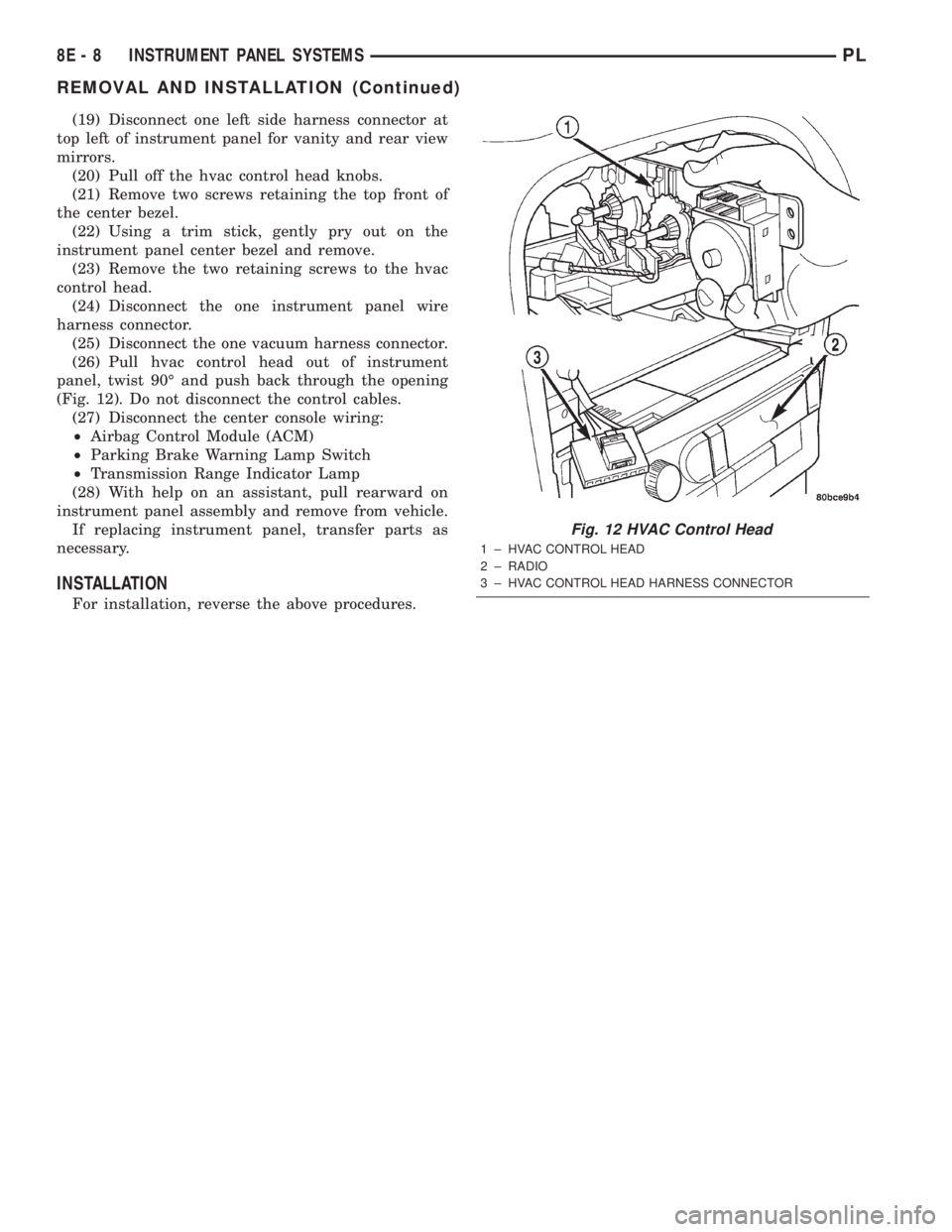
(19) Disconnect one left side harness connector at
top left of instrument panel for vanity and rear view
mirrors.
(20) Pull off the hvac control head knobs.
(21) Remove two screws retaining the top front of
the center bezel.
(22) Using a trim stick, gently pry out on the
instrument panel center bezel and remove.
(23) Remove the two retaining screws to the hvac
control head.
(24) Disconnect the one instrument panel wire
harness connector.
(25) Disconnect the one vacuum harness connector.
(26) Pull hvac control head out of instrument
panel, twist 90É and push back through the opening
(Fig. 12). Do not disconnect the control cables.
(27) Disconnect the center console wiring:
²Airbag Control Module (ACM)
²Parking Brake Warning Lamp Switch
²Transmission Range Indicator Lamp
(28) With help on an assistant, pull rearward on
instrument panel assembly and remove from vehicle.
If replacing instrument panel, transfer parts as
necessary.
INSTALLATION
For installation, reverse the above procedures.
Fig. 12 HVAC Control Head
1 ± HVAC CONTROL HEAD
2 ± RADIO
3 ± HVAC CONTROL HEAD HARNESS CONNECTOR
8E - 8 INSTRUMENT PANEL SYSTEMSPL
REMOVAL AND INSTALLATION (Continued)
Page 256 of 1285
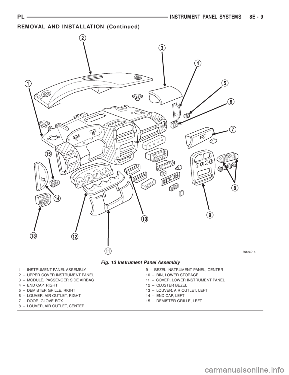
Fig. 13 Instrument Panel Assembly
1 ± INSTRUMENT PANEL ASSEMBLY
2 ± UPPER COVER INSTRUMENT PANEL
3 ± MODULE, PASSENGER SIDE AIRBAG
4 ± END CAP, RIGHT
5 ± DEMISTER GRILLE, RIGHT
6 ± LOUVER, AIR OUTLET, RIGHT
7 ± DOOR, GLOVE BOX
8 ± LOUVER, AIR OUTLET, CENTER9 ± BEZEL INSTRUMENT PANEL, CENTER
10 ± BIN, LOWER STORAGE
11 ± COVER, LOWER INSTRUMENT PANEL
12 ± CLUSTER BEZEL
13 ± LOUVER, AIR OUTLET, LEFT
14 ± END CAP, LEFT
15 ± DEMISTER GRILLE, LEFT
PLINSTRUMENT PANEL SYSTEMS 8E - 9
REMOVAL AND INSTALLATION (Continued)
Page 264 of 1285
(15) Rotate the A/C outlet registers to the full
down position. Grip each outlet at its outboard end
and gently over-rotate to release from its pivot point.
Swing outlet straight out and remove by hand
(16) Remove the (4) HVAC control knobs by pull-
ing them straight off the switch shaft by hand.
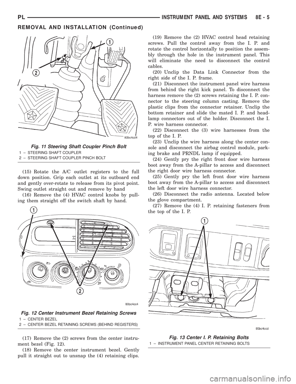
(17) Remove the (2) screws from the center instru-
ment bezel (Fig. 12).
(18) Remove the center instrument bezel. Gently
pull it straight out to unsnap the (4) retaining clips.(19) Remove the (2) HVAC control head retaining
screws. Pull the control away from the I. P. and
rotate the control horizontally to position the assem-
bly through the hole in the instrument panel. This
will eliminate the need to disconnect the control
cables.
(20) Unclip the Data Link Connector from the
right side of the I. P. frame.
(21) Disconnect the instrument panel wire harness
from behind the right kick panel. To disconnect the
harness remove the (2) screws retaining the I. P. con-
nector to the steering column casting. Remove the
plastic clips from the connector retainer. Unclip the
bottom retainer and slide the mated I. P. and head-
lamp connectors out of the holder. Disconnect the I.
P. wire harness connector.
(22) Disconnect the (3) wire harnesses from the
top of the I. P.
(23) Unclip the wire harness along the center con-
sole and disconnect the airbag control module, park-
ing brake and PRNDL lamp if equipped.
(24) Gently pry the right front door wire harness
boot away from the A-pillar to access and disconnect
the right door wire harness connector.
(25) Gently pry the left front door wire harness
boot away from the A-pillar to access and disconnect
the left door wire harness connector.
(26) Disconnect the radio antenna. Located below
the glove compartment.
(27) Remove the (4) I. P. retaining fasteners from
the top of the I. P.
Fig. 11 Steering Shaft Coupler Pinch Bolt
1 ± STEERING SHAFT COUPLER
2 ± STEERING SHAFT COUPLER PINCH BOLT
Fig. 12 Center Instrument Bezel Retaining Screws
1 ± CENTER BEZEL
2±
CENTER BEZEL RETAINING SCREWS (BEHIND REGISTERS)
Fig. 13 Center I. P. Retaining Bolts
1 ± INSTRUMENT PANEL CENTER RETAINING BOLTS
PLINSTRUMENT PANEL AND SYSTEMS 8E - 5
REMOVAL AND INSTALLATION (Continued)
Page 265 of 1285
(28) Remove the (2) I. P. retaining bolts which
attach the I. P. to the body at the tunnel bracket
(Fig. 13).
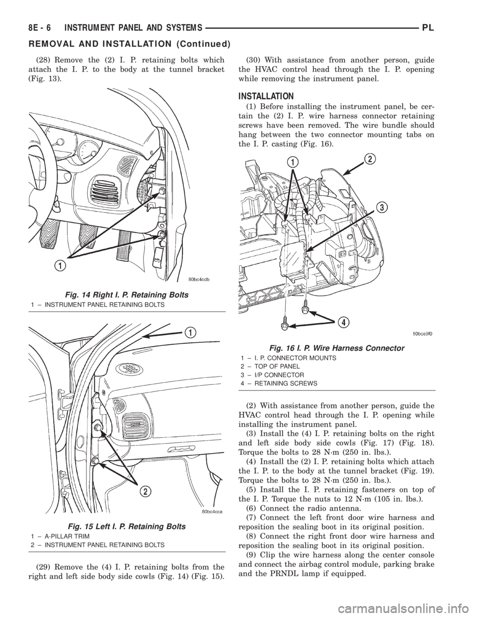
(29) Remove the (4) I. P. retaining bolts from the
right and left side body side cowls (Fig. 14) (Fig. 15).(30) With assistance from another person, guide
the HVAC control head through the I. P. opening
while removing the instrument panel.
INSTALLATION
(1) Before installing the instrument panel, be cer-
tain the (2) I. P. wire harness connector retaining
screws have been removed. The wire bundle should
hang between the two connector mounting tabs on
the I. P. casting (Fig. 16).
(2) With assistance from another person, guide the
HVAC control head through the I. P. opening while
installing the instrument panel.
(3) Install the (4) I. P. retaining bolts on the right
and left side body side cowls (Fig. 17) (Fig. 18).
Torque the bolts to 28 N´m (250 in. lbs.).
(4) Install the (2) I. P. retaining bolts which attach
the I. P. to the body at the tunnel bracket (Fig. 19).
Torque the bolts to 28 N´m (250 in. lbs.).
(5) Install the I. P. retaining fasteners on top of
the I. P. Torque the nuts to 12 N´m (105 in. lbs.).
(6) Connect the radio antenna.
(7) Connect the left front door wire harness and
reposition the sealing boot in its original position.
(8) Connect the right front door wire harness and
reposition the sealing boot in its original position.
(9) Clip the wire harness along the center console
and connect the airbag control module, parking brake
and the PRNDL lamp if equipped.
Fig. 14 Right I. P. Retaining Bolts
1 ± INSTRUMENT PANEL RETAINING BOLTS
Fig. 15 Left I. P. Retaining Bolts
1 ± A-PILLAR TRIM
2 ± INSTRUMENT PANEL RETAINING BOLTS
Fig. 16 I. P. Wire Harness Connector
1 ± I. P. CONNECTOR MOUNTS
2 ± TOP OF PANEL
3 ± I/P CONNECTOR
4 ± RETAINING SCREWS
8E - 6 INSTRUMENT PANEL AND SYSTEMSPL
REMOVAL AND INSTALLATION (Continued)