Page 912 of 1285
SPECIFICATIONS
STEERING COLUMN FASTENER TORQUE
SPECIFICATIONS
DESCRIPTION TORQUE
STEERING WHEEL:
Retaining Nut............ 61N´m(45ft.lbs.)
Airbag Mounting Screws.... 10N´m(90in.lbs.)
Speed Control Switch Screws . 2 N´m (20 in. lbs.)
STEERING COLUMN:
Mounting Nuts.......... 17N´m(150 in. lbs.)
SKIM Mounting Screws..... 3N´m(25in.lbs.)
STEERING COLUMN LOWER COUPLING:
Pinch Bolt.............. 28N´m(250 in. lbs.)
PLSTEERING 19 - 41
Page 1173 of 1285

(3) Remove rear seat closure panel silencer pad as
necessary to gain access to retractor.
(4) Remove bolt attaching seat belt lower anchor to
floor.
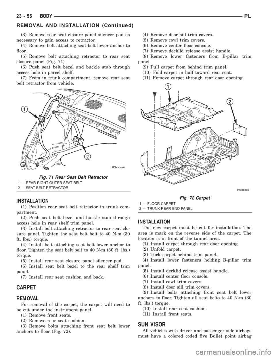
(5) Remove bolt attaching retractor to rear seat
closure panel (Fig. 71).
(6) Push seat belt bezel and buckle stab through
access hole in parcel shelf.
(7) From in trunk compartment, remove rear seat
belt retractor from vehicle.
INSTALLATION
(1) Position rear seat belt retractor in trunk com-
partment.
(2) Push seat belt bezel and buckle stab through
access hole in rear shelf trim panel.
(3) Install bolt attaching retractor to rear seat clo-
sure panel. Tighten the seat belt bolt to 40 N´m (30
ft. lbs.) torque.
(4) Install bolt attaching seat belt lower anchor to
floor. Tighten the seat belt bolt to 40 N´m (30 ft. lbs.)
torque.
(5) Install rear seat closure panel silencer pad.
(6) Install seat belt bezel to the rear shelf trim
panel.
(7) Install rear seat cushion and back.
CARPET
REMOVAL
For removal of the carpet, the carpet will need to
be cut under the instrument panel.
(1) Remove front seats.
(2) Remove rear seat cushion.
(3) Remove bolts attaching front seat belt lower
anchors to floor (Fig. 72).(4) Remove door sill trim covers.
(5) Remove cowl trim covers.
(6) Remove center floor console.
(7) Remove decklid release assist handle.
(8) Remove lower fasteners from B-pillar trim
panel.
(9) Pull carpet from behind trim panel.
(10) Fold carpet in half toward rear seat.
(11) Remove carpet through rear door opening.
INSTALLATION
The new carpet must be cut for installation. The
area is mark on the reverse side of the carpet. The
location is in front of the tunnel area.
(1) Install carpet through rear door opening.
(2) Unfold carpet.
(3) Tuck carpet behind trim panel.
(4) Install lower fasteners holding B-pillar trim
panel.
(5) Install decklid release assist handle.
(6) Install center floor console.
(7) Install cowl trim covers.
(8) Install door sill trim covers.
(9) Install bolts attaching front seat belt lower
anchors to floor. Tighten all seat belts to 40 N´m (30
ft. lbs.) torque.
(10) Install rear seat cushion.
(11) Install front seats.
SUN VISOR
All vehicles with driver and passenger side airbags
must have a colored coded five Bullet point airbag
Fig. 71 Rear Seat Belt Retractor
1 ± REAR RIGHT OUTER SEAT BELT
2 ± SEAT BELT RETRACTOR
Fig. 72 Carpet
1 ± FLOOR CARPET
2 ± TRUNK REAR END PANEL
23 - 56 BODYPL
REMOVAL AND INSTALLATION (Continued)
Page 1275 of 1285

VIN CODE DECODING
POSITION INTERPRETATION CODE = DESCRIPTION
1 Country of Origin 1 = United states
2 MakeB = Dodge
P = Plymouth
3 Vehicle Type 3 = Passenger Car
4 Pass. Safety E = Restraint System, Active Driver & Passenger Airbags
5 Car Line S = Neon
6 Series2 = Low Line
4 = High Line
7 Body Style6 = 4 Door Sedan
8 Engine C = 2.0 L 4 Cyl. 16V
9 Check Digit See explanation in this section.
10 Model Year Y = 2000
11 Assembly Plant D = Belvidere
12 Thru 17 Vehicle Build Sequence 6 digit number assigned by assembly plant.
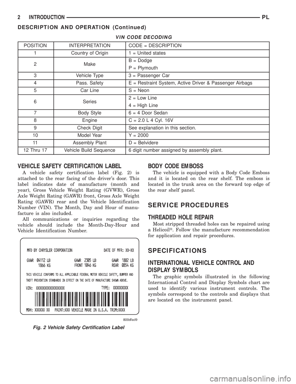
VEHICLE SAFETY CERTIFICATION LABEL
A vehicle safety certification label (Fig. 2) is
attached to the rear facing of the driver's door. This
label indicates date of manufacture (month and
year), Gross Vehicle Weight Rating (GVWR), Gross
Axle Weight Rating (GAWR) front, Gross Axle Weight
Rating (GAWR) rear and the Vehicle Identification
Number (VIN). The Month, Day and Hour of manu-
facture is also included.
All communications or inquiries regarding the
vehicle should include the Month-Day-Hour and
Vehicle Identification Number.
BODY CODE EMBOSS
The vehicle is equipped with a Body Code Emboss
and it is located on the rear shelf. The emboss is
located in the trunk area on the forward top edge of
the rear shelf panel.
SERVICE PROCEDURES
THREADED HOLE REPAIR
Most stripped threaded holes can be repaired using
a Helicoilt. Follow the manufacture recommendation
for application and repair procedures.
SPECIFICATIONS
INTERNATIONAL VEHICLE CONTROL AND
DISPLAY SYMBOLS
The graphic symbols illustrated in the following
International Control and Display Symbols chart are
used to identify various instrument controls. The
symbols correspond to the controls and displays that
are located on the instrument panel.
Fig. 2 Vehicle Safety Certification Label
2 INTRODUCTIONPL
DESCRIPTION AND OPERATION (Continued)
Page 1283 of 1285

VIN DECODING INFORMATION
POSITION INTERPRETATION CODE = DESCRIPTION
1 Country of origin 1 = United States
2 Make C = Chrysler
3 Vehicle Type 3 = Passenger Car
4 Passenger Safety E = Active Restraints, Driver and Passenger Airbags
5 Car Line S = Neon BUX L. H. D.
V = Neon BUX R. H. D.
6 Series M = DD5 5-Speed Manual Transmission
A = 3-Speed Automatic Transmission
7 Body Style7 = 4 Door Pillared Hardtop
8 Engine C = 2.0L 4 Cyl. 16V SOHC
A = 1.8L 4 Cyl. 16V SOHC
9 Check Digit See explanation in this section.
10 Model Year Y = 2000
11 Assembly Plant D = Belvedere Assembly
12 Thru 17 Build Sequence 6 Digit number assigned by assembly plant
E-MARK LABEL
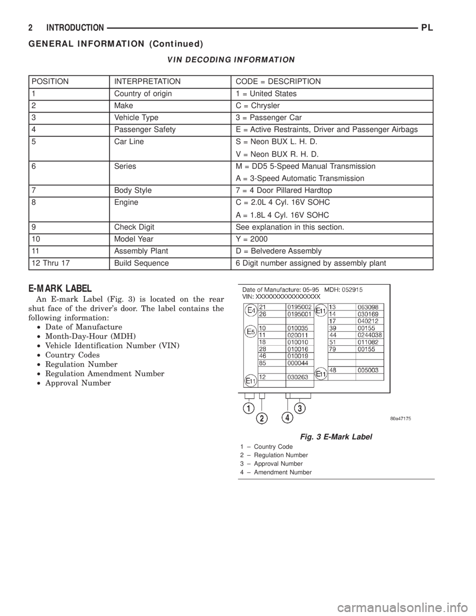
An E-mark Label (Fig. 3) is located on the rear
shut face of the driver's door. The label contains the
following information:
²Date of Manufacture
²Month-Day-Hour (MDH)
²Vehicle Identification Number (VIN)
²Country Codes
²Regulation Number
²Regulation Amendment Number
²Approval Number
Fig. 3 E-Mark Label
1 ± Country Code
2 ± Regulation Number
3 ± Approval Number
4 ± Amendment Number
2 INTRODUCTIONPL
GENERAL INFORMATION (Continued)