2000 DODGE NEON Heating and air conditioning
[x] Cancel search: Heating and air conditioningPage 1 of 1285

GROUP TAB LOCATORINIntroductionINaIntroduction0Lubrication and Maintenance2Suspension3Differential and Driveline5Brakes6Clutch7Cooling8ABattery8BStarting8CCharging System8DIgnition System8EInstrument Panel and Systems8EaInstrument Panel and Systems8FAudio System8GHorns8HVehicle Speed Control System8JTurn Signal and Flashers8KWindshield Wipers and Washers8LLamps8LaLamps8MRestraint System8NElectrically Heated Systems8OPower Distribution Systems8PPower Door Locks8QImmobilizer System8SPower Windows8TPower Mirrors8TaPower Mirrors8UChime Warning/Reminder System8WWiring Diagrams - LHD and RHD9Engine11Exhaust System13Frame and Bumpers14Fuel System19Steering21Transaxle22Tires and Wheels23Body24Heating and Air Conditioning24aHeating and Air Conditioning25Emission Control Systems
Page 185 of 1285
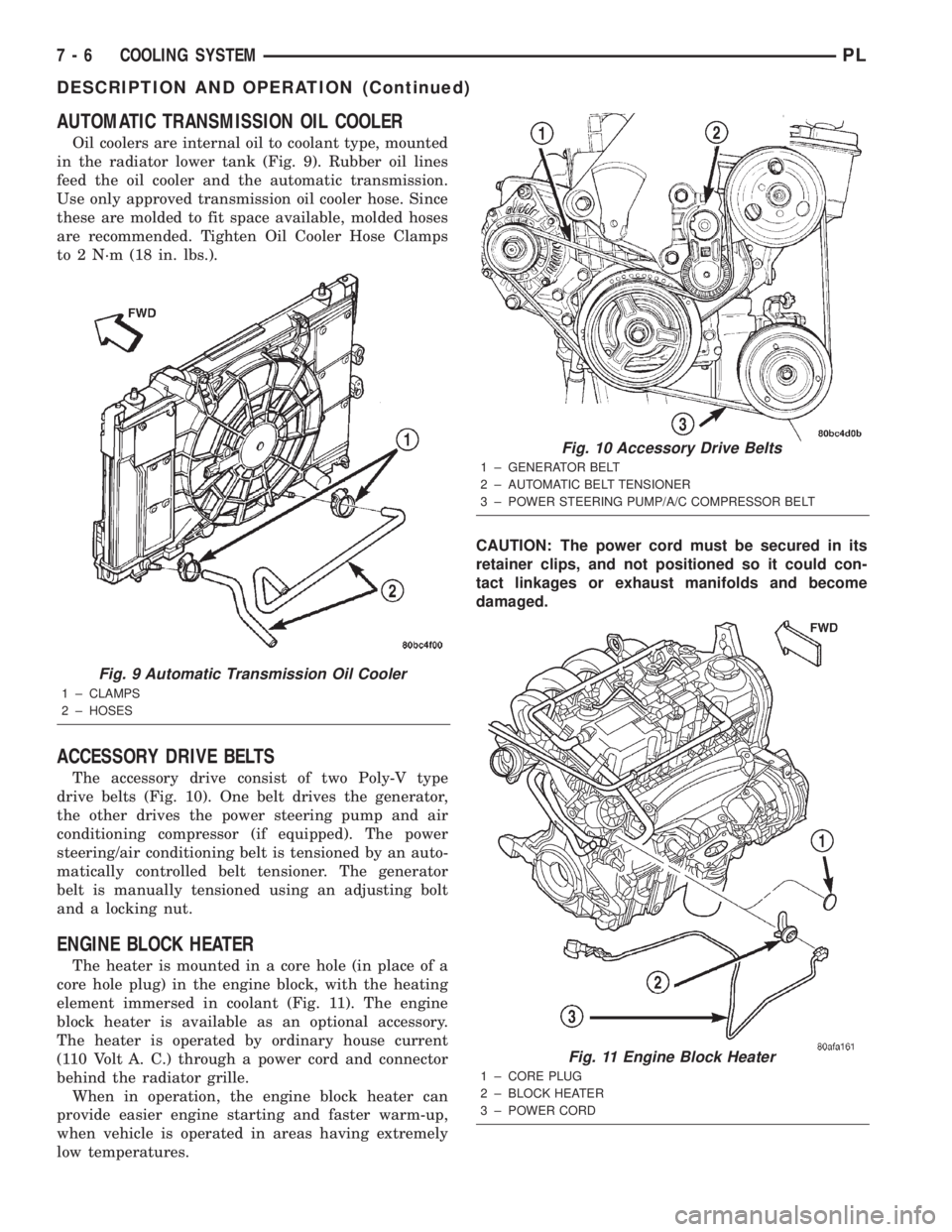
AUTOMATIC TRANSMISSION OIL COOLER
Oil coolers are internal oil to coolant type, mounted
in the radiator lower tank (Fig. 9). Rubber oil lines
feed the oil cooler and the automatic transmission.
Use only approved transmission oil cooler hose. Since
these are molded to fit space available, molded hoses
are recommended. Tighten Oil Cooler Hose Clamps
to 2 N´m (18 in. lbs.).
ACCESSORY DRIVE BELTS
The accessory drive consist of two Poly-V type
drive belts (Fig. 10). One belt drives the generator,
the other drives the power steering pump and air
conditioning compressor (if equipped). The power
steering/air conditioning belt is tensioned by an auto-
matically controlled belt tensioner. The generator
belt is manually tensioned using an adjusting bolt
and a locking nut.
ENGINE BLOCK HEATER
The heater is mounted in a core hole (in place of a
core hole plug) in the engine block, with the heating
element immersed in coolant (Fig. 11). The engine
block heater is available as an optional accessory.
The heater is operated by ordinary house current
(110 Volt A. C.) through a power cord and connector
behind the radiator grille.
When in operation, the engine block heater can
provide easier engine starting and faster warm-up,
when vehicle is operated in areas having extremely
low temperatures.CAUTION: The power cord must be secured in its
retainer clips, and not positioned so it could con-
tact linkages or exhaust manifolds and become
damaged.
Fig. 9 Automatic Transmission Oil Cooler
1 ± CLAMPS
2 ± HOSES
Fig. 10 Accessory Drive Belts
1 ± GENERATOR BELT
2 ± AUTOMATIC BELT TENSIONER
3 ± POWER STEERING PUMP/A/C COMPRESSOR BELT
Fig. 11 Engine Block Heater
1 ± CORE PLUG
2 ± BLOCK HEATER
3 ± POWER CORD
7 - 6 COOLING SYSTEMPL
DESCRIPTION AND OPERATION (Continued)
Page 186 of 1285
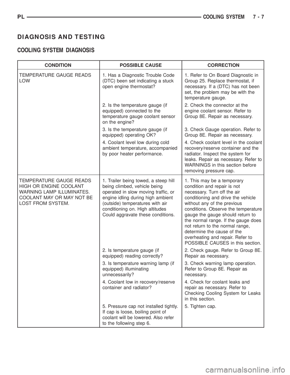
DIAGNOSIS AND TESTING
COOLING SYSTEM DIAGNOSIS
CONDITION POSSIBLE CAUSE CORRECTION
TEMPERATURE GAUGE READS
LOW1. Has a Diagnostic Trouble Code
(DTC) been set indicating a stuck
open engine thermostat?1. Refer to On Board Diagnostic in
Group 25. Replace thermostat, if
necessary. If a (DTC) has not been
set, the problem may be with the
temperature gauge.
2. Is the temperature gauge (if
equipped) connected to the
temperature gauge coolant sensor
on the engine?2. Check the connector at the
engine coolant sensor. Refer to
Group 8E. Repair as necessary.
3. Is the temperature gauge (if
equipped) operating OK?3. Check Gauge operation. Refer to
Group 8E. Repair as necessary.
4. Coolant level low during cold
ambient temperature, accompanied
by poor heater performance.4. Check coolant level in the coolant
recovery/reserve container and the
radiator. Inspect the system for
leaks. Repair as necessary. Refer to
WARNINGS in this section before
removing pressure cap.
TEMPERATURE GAUGE READS
HIGH OR ENGINE COOLANT
WARNING LAMP ILLUMINATES.
COOLANT MAY OR MAY NOT BE
LOST FROM SYSTEM.1. Trailer being towed, a steep hill
being climbed, vehicle being
operated in slow moving traffic, or
engine idling during high ambient
(outside) temperatures with air
conditioning on. High altitudes
Could aggravate these conditions.1. This may be a temporary
condition and repair is not
necessary. Turn off the air
conditioning and drive the vehicle
without any of the previous
conditions. Observe the temperature
gauge the gauge should return to
the normal range. If the gauge does
not return to the normal range,
determine the cause of the
overheating and repair. Refer to
POSSIBLE CAUSES in this section.
2. Is temperature gauge (if
equipped) reading correctly?2. Check gauge. Refer to Group 8E.
Repair as necessary.
3. Is temperature warning lamp (if
equipped) illuminating
unnecessarily?3. Check warning lamp operation.
Refer to Group 8E. Repair as
necessary.
4. Coolant low in recovery/reserve
container and radiator?4. Check for coolant leaks and
repair as necessary. Refer to
Checking Cooling System for Leaks
in this section.
5. Pressure cap not installed tightly.
If cap is loose, boiling point of
coolant will be lowered. Also refer
to the following step 6.5. Tighten cap.
PLCOOLING SYSTEM 7 - 7
Page 188 of 1285
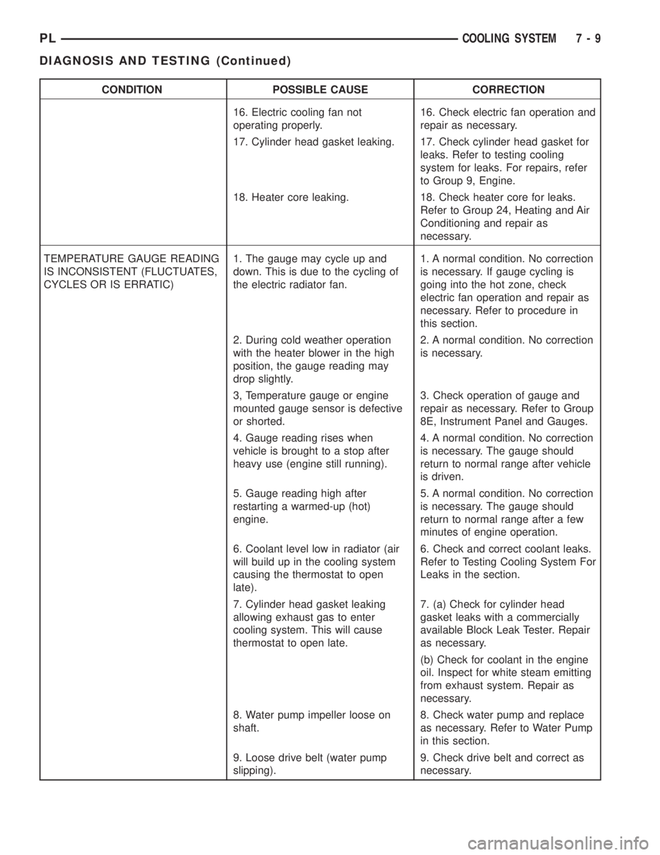
CONDITION POSSIBLE CAUSE CORRECTION
16. Electric cooling fan not
operating properly.16. Check electric fan operation and
repair as necessary.
17. Cylinder head gasket leaking. 17. Check cylinder head gasket for
leaks. Refer to testing cooling
system for leaks. For repairs, refer
to Group 9, Engine.
18. Heater core leaking. 18. Check heater core for leaks.
Refer to Group 24, Heating and Air
Conditioning and repair as
necessary.
TEMPERATURE GAUGE READING
IS INCONSISTENT (FLUCTUATES,
CYCLES OR IS ERRATIC)1. The gauge may cycle up and
down. This is due to the cycling of
the electric radiator fan.1. A normal condition. No correction
is necessary. If gauge cycling is
going into the hot zone, check
electric fan operation and repair as
necessary. Refer to procedure in
this section.
2. During cold weather operation
with the heater blower in the high
position, the gauge reading may
drop slightly.2. A normal condition. No correction
is necessary.
3, Temperature gauge or engine
mounted gauge sensor is defective
or shorted.3. Check operation of gauge and
repair as necessary. Refer to Group
8E, Instrument Panel and Gauges.
4. Gauge reading rises when
vehicle is brought to a stop after
heavy use (engine still running).4. A normal condition. No correction
is necessary. The gauge should
return to normal range after vehicle
is driven.
5. Gauge reading high after
restarting a warmed-up (hot)
engine.5. A normal condition. No correction
is necessary. The gauge should
return to normal range after a few
minutes of engine operation.
6. Coolant level low in radiator (air
will build up in the cooling system
causing the thermostat to open
late).6. Check and correct coolant leaks.
Refer to Testing Cooling System For
Leaks in the section.
7. Cylinder head gasket leaking
allowing exhaust gas to enter
cooling system. This will cause
thermostat to open late.7. (a) Check for cylinder head
gasket leaks with a commercially
available Block Leak Tester. Repair
as necessary.
(b) Check for coolant in the engine
oil. Inspect for white steam emitting
from exhaust system. Repair as
necessary.
8. Water pump impeller loose on
shaft.8. Check water pump and replace
as necessary. Refer to Water Pump
in this section.
9. Loose drive belt (water pump
slipping).9. Check drive belt and correct as
necessary.
PLCOOLING SYSTEM 7 - 9
DIAGNOSIS AND TESTING (Continued)
Page 190 of 1285
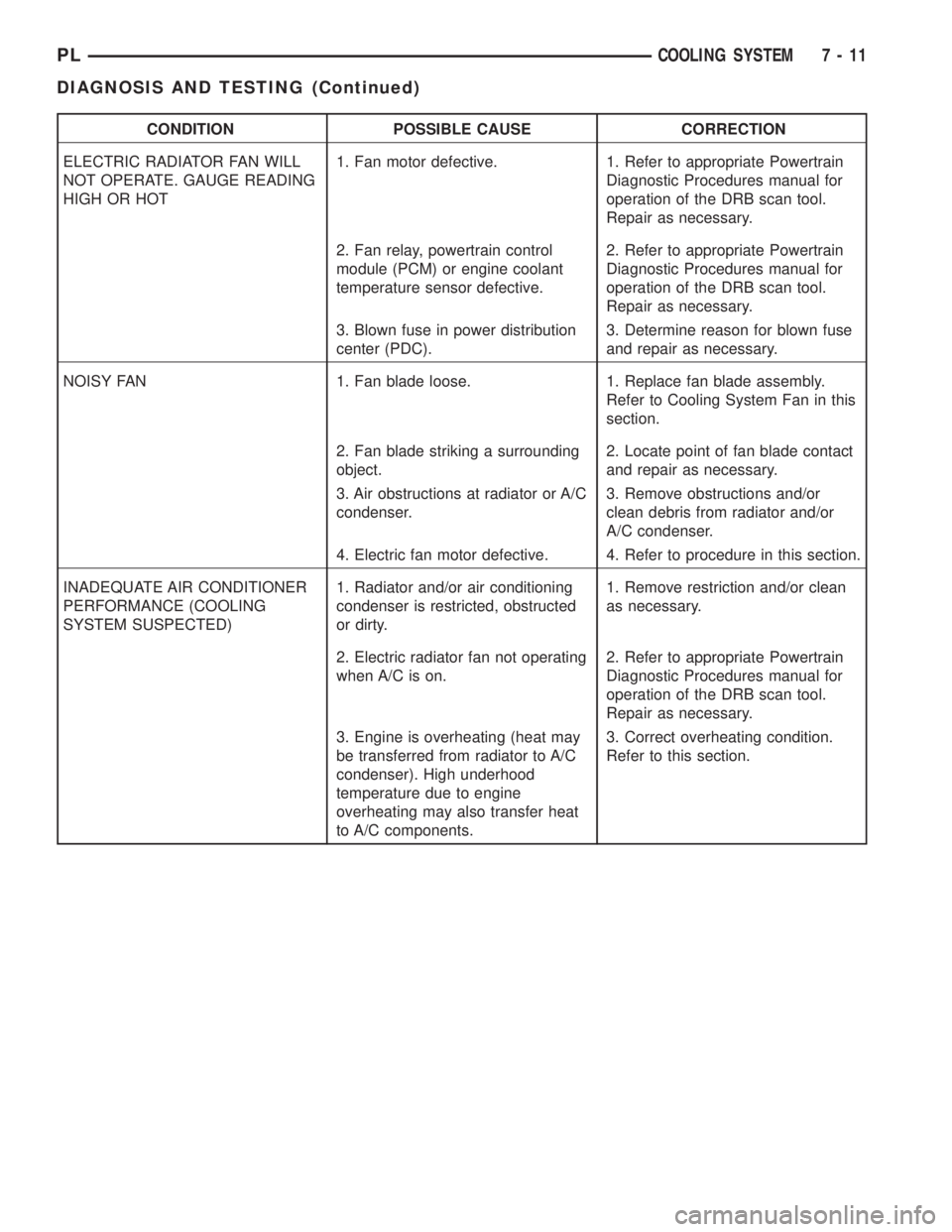
CONDITION POSSIBLE CAUSE CORRECTION
ELECTRIC RADIATOR FAN WILL
NOT OPERATE. GAUGE READING
HIGH OR HOT1. Fan motor defective. 1. Refer to appropriate Powertrain
Diagnostic Procedures manual for
operation of the DRB scan tool.
Repair as necessary.
2. Fan relay, powertrain control
module (PCM) or engine coolant
temperature sensor defective.2. Refer to appropriate Powertrain
Diagnostic Procedures manual for
operation of the DRB scan tool.
Repair as necessary.
3. Blown fuse in power distribution
center (PDC).3. Determine reason for blown fuse
and repair as necessary.
NOISY FAN 1. Fan blade loose. 1. Replace fan blade assembly.
Refer to Cooling System Fan in this
section.
2. Fan blade striking a surrounding
object.2. Locate point of fan blade contact
and repair as necessary.
3. Air obstructions at radiator or A/C
condenser.3. Remove obstructions and/or
clean debris from radiator and/or
A/C condenser.
4. Electric fan motor defective. 4. Refer to procedure in this section.
INADEQUATE AIR CONDITIONER
PERFORMANCE (COOLING
SYSTEM SUSPECTED)1. Radiator and/or air conditioning
condenser is restricted, obstructed
or dirty.1. Remove restriction and/or clean
as necessary.
2. Electric radiator fan not operating
when A/C is on.2. Refer to appropriate Powertrain
Diagnostic Procedures manual for
operation of the DRB scan tool.
Repair as necessary.
3. Engine is overheating (heat may
be transferred from radiator to A/C
condenser). High underhood
temperature due to engine
overheating may also transfer heat
to A/C components.3. Correct overheating condition.
Refer to this section.
PLCOOLING SYSTEM 7 - 11
DIAGNOSIS AND TESTING (Continued)
Page 749 of 1285
(4) Discharge air conditioning system, if equipped.
Refer to Group 24, Heating and Air Conditioning for
procedure.
(5) Disconnect the following: air intake duct at
intake manifold, throttle cables, electrical connectors
from throttle body and air cleaner housing.
(6) Remove air cleaner housing assembly.
(7) Remove upper radiator hose and fan module.
Refer to Group 7, Cooling System for procedure.
(8) Remove lower radiator hose.
(9) Disconnect automatic transmission cooler lines
and plug, if equipped.
(10) Disconnect shift linkage, electrical connectors,
and clutch cable, if equipped with manual transaxle.
(11) Disconnect engine wiring harness.
(12) Disconnect positive cable from Power Distri-
bution Center (PDC) and ground wire from vehicle
body.
(13) Disconnect ground wire from the vehicle body-
to-engine at the right side strut tower.
(14) Disconnect heater hoses.
(15) Disconnect vacuum hose from brake booster.
(16) Disconnect coolant reserve/recovery hose.
(17) Remove accessory drive belts. Refer to Group
7, Cooling System for procedure.
(18) Remove power steering pump and reservoir
and set them aside.
(19) Hoist vehicle and remove right inner splash
shield.
(20) Drain engine oil.
(21) Remove front wheels.
(22) Remove axle shafts. Refer to Group 3, Differ-
ential and Driveline for procedure.
(23) Disconnect exhaust system from manifold.
(24) Disconnect the downstream oxygen sensor
connector.
(25) Remove lower engine torque strut.
(26) Remove structural collar. Refer to procedure
in this section.
(27) Lower vehicle and remove A/C compressor.
(28) Raise vehicle enough to allow engine dolly
and cradle, Special Tools 6135 and 6710 to be
installed under vehicle.
(29) Loosen engine support posts to allow move-
ment for positioning onto engine locating holes and
flange on the engine bedplate. Lower vehicle and
position cradle until the engine is resting on support
posts (Fig. 26). Tighten mounts to cradle frame. This
will keep support posts from moving when removing
or installing engine and transmission.
(30) Install safety straps around the engine to cra-
dle (Fig. 26). Tighten straps and lock them into posi-
tion.
WARNING: Safety straps MUST be used.(31) Raise vehicle enough to see if straps are tight
enough to hold cradle assembly to engine.
(32) Lower vehicle so weight of the engine and
transmission ONLY is on the cradle assembly.
(33) Remove the upper engine torque strut.
(34) Remove right and left engine and transaxle
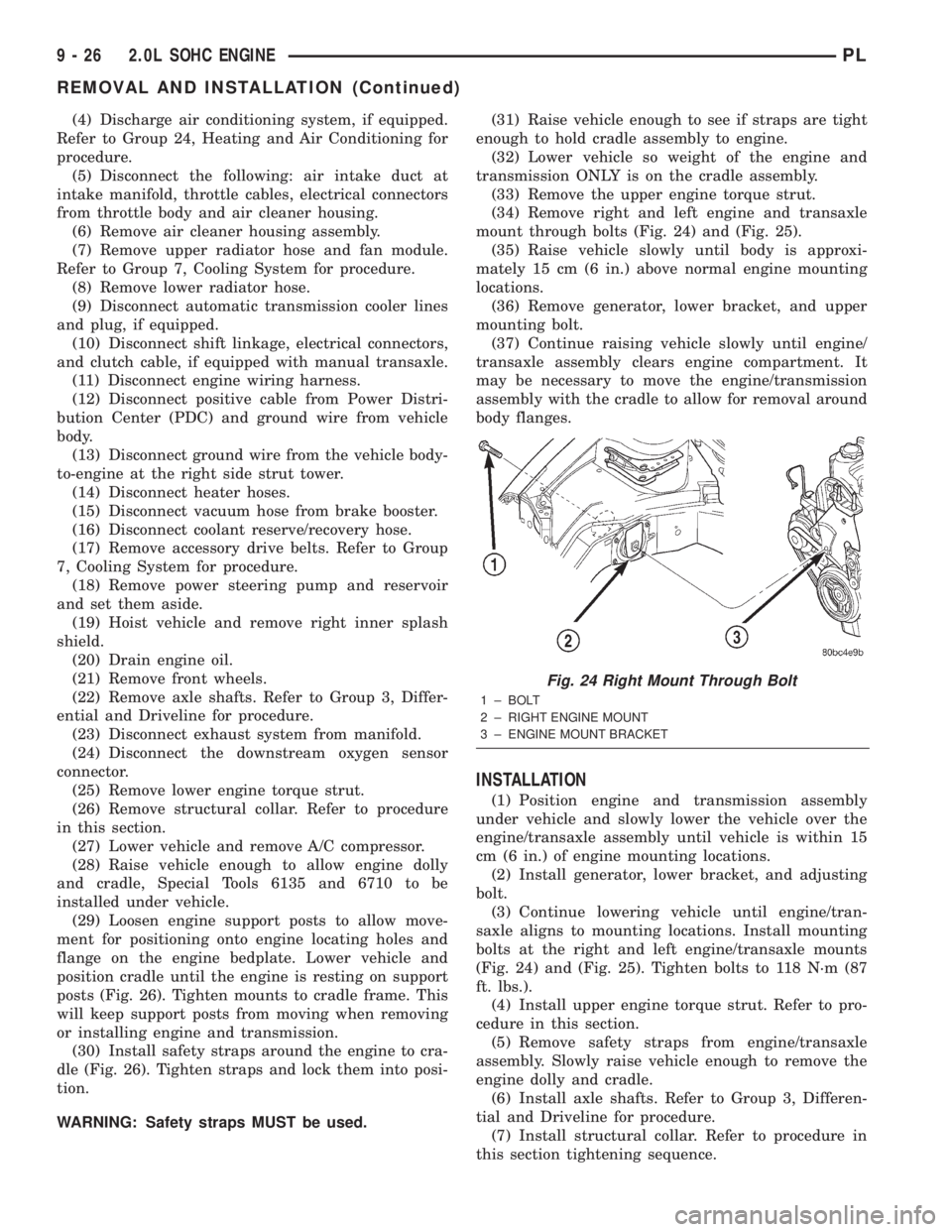
mount through bolts (Fig. 24) and (Fig. 25).
(35) Raise vehicle slowly until body is approxi-
mately 15 cm (6 in.) above normal engine mounting
locations.
(36) Remove generator, lower bracket, and upper
mounting bolt.
(37) Continue raising vehicle slowly until engine/
transaxle assembly clears engine compartment. It
may be necessary to move the engine/transmission
assembly with the cradle to allow for removal around
body flanges.
INSTALLATION
(1) Position engine and transmission assembly
under vehicle and slowly lower the vehicle over the
engine/transaxle assembly until vehicle is within 15
cm (6 in.) of engine mounting locations.
(2) Install generator, lower bracket, and adjusting
bolt.
(3) Continue lowering vehicle until engine/tran-
saxle aligns to mounting locations. Install mounting
bolts at the right and left engine/transaxle mounts
(Fig. 24) and (Fig. 25). Tighten bolts to 118 N´m (87
ft. lbs.).
(4) Install upper engine torque strut. Refer to pro-
cedure in this section.
(5) Remove safety straps from engine/transaxle
assembly. Slowly raise vehicle enough to remove the
engine dolly and cradle.
(6) Install axle shafts. Refer to Group 3, Differen-
tial and Driveline for procedure.
(7) Install structural collar. Refer to procedure in
this section tightening sequence.
Fig. 24 Right Mount Through Bolt
1 ± BOLT
2 ± RIGHT ENGINE MOUNT
3 ± ENGINE MOUNT BRACKET
9 - 26 2.0L SOHC ENGINEPL
REMOVAL AND INSTALLATION (Continued)
Page 845 of 1285
²All inputs monitored for proper voltage range.
²All monitored components (refer to the Emission
section for On-Board Diagnostics).
The PCM compares the upstream and downstream
heated oxygen sensor inputs to measure catalytic
convertor efficiency. If the catalyst efficiency drops
below the minimum acceptable percentage, the PCM
stores a diagnostic trouble code in memory.
During certain idle conditions, the PCM may enter
a variable idle speed strategy. During variable idle
speed strategy the PCM adjusts engine speed based
on the following inputs.
²A/C sense
²Battery voltage
²Battery temperature
²Engine coolant temperature
²Engine run time
²Power steering pressure switch
²Vehicle mileage
ACCELERATION MODE
This is a CLOSED LOOP mode. The PCM recog-
nizes an abrupt increase in Throttle Position sensor
output voltage or MAP sensor output voltage as a
demand for increased engine output and vehicle
acceleration. The PCM increases injector pulse width
in response to increased fuel demand.
DECELERATION MODE
This is a CLOSED LOOP mode. During decelera-
tion the following inputs are received by the PCM:
²A/C pressure transducer
²A/C sense
²Battery voltage
²Intake air temperature
²Engine coolant temperature
²Crankshaft position (engine speed)
²Exhaust gas oxygen content (upstream heated
oxygen sensor)
²Knock sensor
²Manifold absolute pressure
²Power steering pressure switch
²Throttle position
²IAC motor control changes in response to MAP
sensor feedback.
The PCM may receive a closed throttle input from
the Throttle Position Sensor (TPS) when it senses an
abrupt decrease in manifold pressure. This indicates
a hard deceleration. In response, the PCM may
momentarily turn off the injectors. This helps
improve fuel economy, emissions and engine braking.
If decel fuel shutoff is detected, downstream oxy-
gen sensor diagnostics is performed.WIDE-OPEN-THROTTLE MODE
This is an OPEN LOOP mode. During wide-open-
throttle operation, the following inputs are received
by the PCM:
²Intake air temperature
²Engine coolant temperature
²Engine speed
²Knock sensor
²Manifold absolute pressure
²Throttle position
When the PCM senses a wide-open-throttle condi-
tion through the Throttle Position Sensor (TPS) it de-
energizes the A/C compressor clutch relay. This
disables the air conditioning system.
The PCM does not monitor the heated oxygen sen-
sor inputs during wide-open-throttle operation except
for downstream heated oxygen sensor and both
shorted diagnostics. The PCM adjusts injector pulse
width to supply a predetermined amount of addi-
tional fuel.
IGNITION SWITCH OFF MODE
When the operator turns the ignition switch to the
OFF position, the following occurs:
²All outputs are turned off, unless 02 Heater
Monitor test is being run. Refer to the Emission sec-
tion for On-Board Diagnostics.
²No inputs are monitored except for the heated
oxygen sensors. The PCM monitors the heating ele-
ments in the oxygen sensors and then shuts down.
SYSTEM DIAGNOSIS
OPERATION
The PCM can test many of its own input and out-
put circuits. If the PCM senses a fault in a major
system, the PCM stores a Diagnostic Trouble Code
(DTC) in memory.
For DTC information see On-Board Diagnostics.
POWER DISTRIBUTION CENTER
The Power Distribution Center (PDC) is located
next to the battery (Fig. 1). The PDC contains the
starter relay, radiator fan relay, A/C compressor
clutch relay, auto shutdown relay, fuel pump relay
and several fuses.
POWERTRAIN CONTROL MODULE
The Powertrain Control Module (PCM) is a digital
computer containing a microprocessor (Fig. 2). The
PCM receives input signals from various switches
and sensors that are referred to as PCM Inputs.
Based on these inputs, the PCM adjusts various
engine and vehicle operations through devices that
are referred to as PCM Outputs.
PCM Inputs:
14 - 24 FUEL SYSTEMPL
DESCRIPTION AND OPERATION (Continued)
Page 848 of 1285
As the engine enters one of these cells the PCM
looks at the amount of short term correction being
used. Because the goal is to keep short term at 0 (O2
Sensor switching at 0.5 volt), long term will update
in the same direction as short term correction was
moving to bring the short term back to 0. Once short
term is back at 0, this long term correction factor is
stored in memory.
The values stored in long term adaptive memory
are used for all operating conditions, including open
loop. However, the updating of the long term memoryoccurs after the engine has exceeded approximately
17É F, with fuel control in closed loop and two min-
utes of engine run time. This is done to prevent any
transitional temperature or start-up compensations
from corrupting long term fuel correction.
Long term adaptive memory can change the pulse-
width by as much as 25%, which means it can correct
for all of short term. It is possible to have a problem
that would drive long term to 25% and short term to
another 25% for a total change of 50% away from
base pulse-width calculation.
TYPICAL ADAPTIVE MEMORY FUEL CELLS
Open
ThrottleOpen
ThrottleOpen
ThrottleOpen
ThrottleOpen
ThrottleOpen
Throttle Idle Decel
Vacuum 20 17 13 9 5 0
Above 1,984
rpm1 3 5 7 9 11 13 Drive 15
Below 1,984
rpm02 4 6 8 1012
Neutral14
MAP volt =0 1.4 2.0 2.6 3.3 3.9
Fuel Correction Diagnostics
There are two fuel correction diagnostic routines:
²Fuel System Rich
²Fuel System Lean
A DTC is set and the MIL is illuminated if the
PCM detects either of these conditions.
PROGRAMMABLE COMMUNICATIONS
INTERFACE (PCI) BUS
OPERATION
Various modules exchange information through a
communications port called the PCI Bus. The Power-
train Control Module (PCM) transmits the Malfunc-
tion Indicator Lamp (Check Engine) On/Off signal
and engine RPM on the PCI Bus. The PCM receives
the Air Conditioning select input, transaxle gear
position inputs over the PCI Bus. The PCM also
receives the air conditioning evaporator temperature
signal from the PCI Bus.
The following components access or send informa-
tion on the PCI Bus.
²Instrument Panel
²Body Control Module
²Air Bag System Diagnostic Module
²Full ATC Display Head
²ABS Module
²Transmission Control Module
²Powertrain Control Module
²Overhead Travel Module
AIR CONDITIONING PRESSURE
TRANSDUCERÐPCM INPUT
OPERATION
The Powertrain Control Module (PCM) monitors
the A/C compressor discharge (high side) pressure
through the air conditioning pressure transducer.
The transducer supplies an input to the PCM. The
PCM engages the A/C compressor clutch if pressure
is sufficient for A/C system operation.
AUTOMATIC SHUTDOWN (ASD) SENSEÐPCM
INPUT
OPERATION
The ASD sense circuit informs the PCM when the
ASD relay energizes. A 12 volt signal at this input
indicates to the PCM that the ASD has been acti-
vated. This input is used only to sense that the ASD
relay is energized.
When energized, the ASD relay supplies battery
voltage to the fuel injectors, ignition coils and the
heating element in each oxygen sensor. If the PCM
does not receive 12 volts from this input after
grounding the ASD relay, it sets a Diagnostic Trouble
Code (DTC).
PLFUEL SYSTEM 14 - 27
DESCRIPTION AND OPERATION (Continued)