2000 DODGE NEON sensor
[x] Cancel search: sensorPage 25 of 1285
CAUTION: No attempt should be made to service
the headless grease fitting on the ball joint. It has
been purposely snapped off by the manufacturer to
avoid over-greasing.
STABILIZER BAR (FRONT)
Inspect for broken, cracked or distorted stabilizer
bar cushions and retainers. Inspect for worn or dam-
aged stabilizer bar links (Fig. 1).
SERVICE PROCEDURES
LUBRICATION
There are no serviceable lubrication points on the
front suspension. The front lower ball joints have
grease fittings which have had the head snapped off
by the manufacturer after they have been filled. This
has been done to eliminate the possibility of damag-
ing the non-vented seals. Grease will not leak from
the broken grease fittings. The ball joints are sealed
for life and require no maintenance.
CAUTION: No attempt should be made to replace
the ball joint grease fitting with a new fitting, then
filling the ball joint with grease. Damage to the
grease seal can result.
REMOVAL AND INSTALLATION
SERVICE WARNINGS AND CAUTIONS
WARNING: DO NOT REMOVE THE STRUT SHAFT
NUT WHILE STRUT ASSEMBLY IS INSTALLED IN
VEHICLE, OR BEFORE THE COIL SPRING IS COM-
PRESSED WITH A COMPRESSION TOOL. THE
SPRING IS HELD UNDER HIGH PRESSURE.
CAUTION: Only frame contact hoisting equipment
can be used on this vehicle. All vehicles have a
fully independent rear suspension. The vehicles
cannot be hoisted using equipment designed to lift
a vehicle by the rear axle. If this type of hoisting
equipment is used, damage to rear suspension
components will occur.
CAUTION: At no time when servicing a vehicle can
a sheet metal screw, bolt, or other metal fastener be
installed in the shock tower to take the place of an
original plastic clip. It may come into contact with
the strut or coil spring.CAUTION: Wheel bearing damage will result if after
loosening the hub nut, the vehicle is rolled on the
ground or the weight of the vehicle is allowed to be
supported by the tires for a length of time.
STRUT ASSEMBLY (FRONT)
NOTE: Before proceeding with this procedure,
review SERVICE WARNINGS AND CAUTIONS at the
beginning of REMOVAL AND INSTALLATION in this
section.
REMOVAL
(1) Raise the vehicle. Refer to HOISTING in the
LUBRICATION AND MAINTENANCE group for the
proper lifting procedure.
(2) Remove tire and wheel assembly from location
on front of vehicle requiring strut removal.
(3) If both strut assemblies are to be removed,
mark the strut assemblies right or left according to
which side of the vehicle they were removed from.
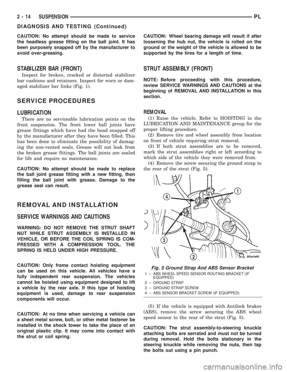
(4) Remove the screw securing the ground strap to
the rear of the strut (Fig. 5).
(5) If the vehicle is equipped with Antilock brakes
(ABS), remove the screw securing the ABS wheel
speed sensor to the rear of the strut (Fig. 5).
CAUTION: The strut assembly-to-steering knuckle
attaching bolts are serrated and must not be turned
during removal. Hold the bolts stationary in the
steering knuckle while removing the nuts, then tap
the bolts out using a pin punch.
Fig. 5 Ground Strap And ABS Sensor Bracket
1 ± ABS WHEEL SPEED SENSOR ROUTING BRACKET (IF
EQUIPPED)
2 ± GROUND STRAP
3 ± GROUND STRAP SCREW
4 ± ABS SENSOR BRACKET SCREW (IF EQUIPPED)
2 - 14 SUSPENSIONPL
DIAGNOSIS AND TESTING (Continued)
Page 26 of 1285
(6) Remove the two bolts attaching the strut to the
steering knuckle (Fig. 1).
(7) Lower the vehicle just enough to open the
hood, but without letting the tires touch the floor.
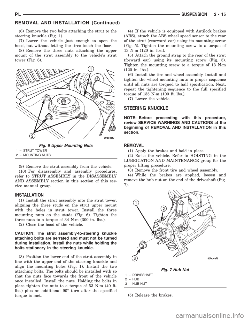
(8) Remove the three nuts attaching the upper
mount of the strut assembly to the vehicle's strut
tower (Fig. 6).
(9) Remove the strut assembly from the vehicle.
(10) For disassembly and assembly procedures,
refer to STRUT ASSEMBLY in the DISASSEMBLY
AND ASSEMBLY section in this section of this ser-
vice manual group.
INSTALLATION
(1) Install the strut assembly into the strut tower,
aligning the three studs on the strut upper mount
with the holes in strut tower. Install the three
mounting nuts on the studs (Fig. 6). Tighten the
three nuts to a torque of 34 N´m (300 in. lbs.).
(2) Close the hood of the vehicle.
CAUTION: The strut assembly-to-steering knuckle
attaching bolts are serrated and must not be turned
during installation. Install the nuts while holding the
bolts stationary in the steering knuckle.
(3) Position the lower end of the strut assembly in
line with the upper end of the steering knuckle and
align the mounting holes (Fig. 1). Install the two
attaching bolts. The bolts should be installed with so
that the nuts face towards the front of the vehicle
once installed. Install the nuts. Holding the bolts in
place tighten the nuts to a torque of 53 N´m (40 ft.
lbs.) plus an additional 90É turn after the specified
torque is met.(4) If the vehicle is equipped with Antilock brakes
(ABS), attach the ABS wheel speed sensor to the rear
of the strut (rearward ear) using its mounting screw
(Fig. 5). Tighten the mounting screw to a torque of
13 N´m (120 in. lbs.).
(5) Attach the ground strap to the rear of the strut
(forward ear) using its mounting screw (Fig. 5).
Tighten the mounting screw to a torque of 13 N´m
(120 in. lbs.).
(6) Install the tire and wheel assembly. Install and
tighten the wheel mounting nuts in proper sequence
until all nuts are torqued to half specification. Next,
repeat the tightening sequence to the full specified
torque of 135 N´m (100 ft. lbs.).
(7) Lower the vehicle.
STEERING KNUCKLE
NOTE: Before proceeding with this procedure,
review SERVICE WARNINGS AND CAUTIONS at the
beginning of REMOVAL AND INSTALLATION in this
section.
REMOVAL
(1) Apply the brakes and hold in place.
(2) Raise the vehicle. Refer to HOISTING in the
LUBRICATION AND MAINTENANCE group for the
proper lifting procedure.
(3) Remove the front tire and wheel assembly.
(4) While the brakes are applied, loosen and
remove the hub nut on the end of the driveshaft (Fig.
7).
(5) Release the brakes.
Fig. 6 Upper Mounting Nuts
1 ± STRUT TOWER
2 ± MOUNTING NUTS
Fig. 7 Hub Nut
1 ± DRIVESHAFT
2 ± HUB
3 ± HUB NUT
PLSUSPENSION 2 - 15
REMOVAL AND INSTALLATION (Continued)
Page 48 of 1285
For more information on the description and oper-
ation of an individual component, refer to the appli-
cable component heading in this section.
STRUT ASSEMBLY (REAR)
The rear strut assemblies support the weight of
the vehicle using coil springs positioned around
struts. The coil springs are contained between the
upper mount of the strut assembly and a lower
spring seat on the body of the strut.
The top of each strut assembly is bolted to the top
of the inner fender through a rubber isolated mount.
The bottom of the strut assembly attaches to the rear
knuckle using 2 thru-bolts with prevailing torque
nuts.
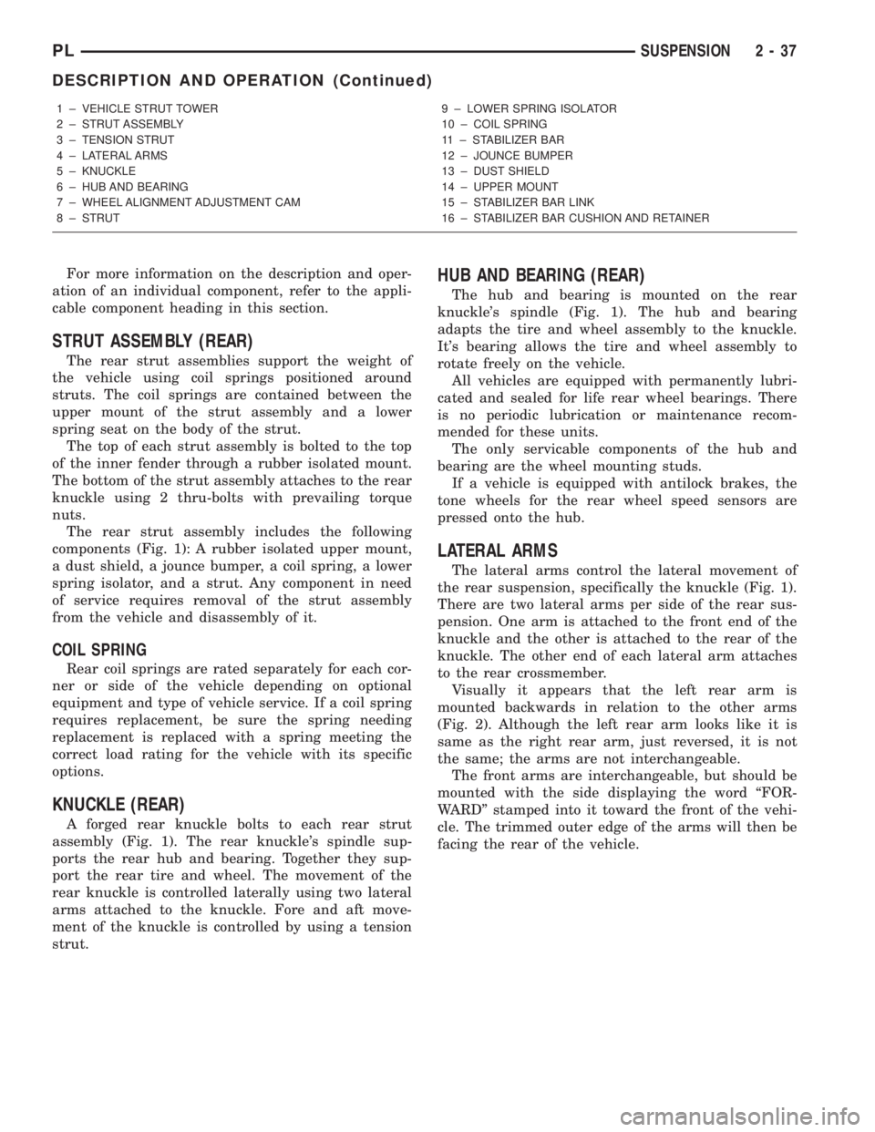
The rear strut assembly includes the following
components (Fig. 1): A rubber isolated upper mount,
a dust shield, a jounce bumper, a coil spring, a lower
spring isolator, and a strut. Any component in need
of service requires removal of the strut assembly
from the vehicle and disassembly of it.
COIL SPRING
Rear coil springs are rated separately for each cor-
ner or side of the vehicle depending on optional
equipment and type of vehicle service. If a coil spring
requires replacement, be sure the spring needing
replacement is replaced with a spring meeting the
correct load rating for the vehicle with its specific
options.
KNUCKLE (REAR)
A forged rear knuckle bolts to each rear strut
assembly (Fig. 1). The rear knuckle's spindle sup-
ports the rear hub and bearing. Together they sup-
port the rear tire and wheel. The movement of the
rear knuckle is controlled laterally using two lateral
arms attached to the knuckle. Fore and aft move-
ment of the knuckle is controlled by using a tension
strut.
HUB AND BEARING (REAR)
The hub and bearing is mounted on the rear
knuckle's spindle (Fig. 1). The hub and bearing
adapts the tire and wheel assembly to the knuckle.
It's bearing allows the tire and wheel assembly to
rotate freely on the vehicle.
All vehicles are equipped with permanently lubri-
cated and sealed for life rear wheel bearings. There
is no periodic lubrication or maintenance recom-
mended for these units.
The only servicable components of the hub and
bearing are the wheel mounting studs.
If a vehicle is equipped with antilock brakes, the
tone wheels for the rear wheel speed sensors are
pressed onto the hub.
LATERAL ARMS
The lateral arms control the lateral movement of
the rear suspension, specifically the knuckle (Fig. 1).
There are two lateral arms per side of the rear sus-
pension. One arm is attached to the front end of the
knuckle and the other is attached to the rear of the
knuckle. The other end of each lateral arm attaches
to the rear crossmember.
Visually it appears that the left rear arm is
mounted backwards in relation to the other arms
(Fig. 2). Although the left rear arm looks like it is
same as the right rear arm, just reversed, it is not
the same; the arms are not interchangeable.
The front arms are interchangeable, but should be
mounted with the side displaying the word ªFOR-
WARDº stamped into it toward the front of the vehi-
cle. The trimmed outer edge of the arms will then be
facing the rear of the vehicle.
1 ± VEHICLE STRUT TOWER
2 ± STRUT ASSEMBLY
3 ± TENSION STRUT
4 ± LATERAL ARMS
5 ± KNUCKLE
6 ± HUB AND BEARING
7 ± WHEEL ALIGNMENT ADJUSTMENT CAM
8 ± STRUT9 ± LOWER SPRING ISOLATOR
10 ± COIL SPRING
11 ± STABILIZER BAR
12 ± JOUNCE BUMPER
13 ± DUST SHIELD
14 ± UPPER MOUNT
15 ± STABILIZER BAR LINK
16 ± STABILIZER BAR CUSHION AND RETAINER
PLSUSPENSION 2 - 37
DESCRIPTION AND OPERATION (Continued)
Page 51 of 1285
REMOVAL AND INSTALLATION
SERVICE WARNINGS AND CAUTIONS
WARNING: DO NOT REMOVE THE STRUT SHAFT
NUT WHILE STRUT ASSEMBLY IS INSTALLED IN
VEHICLE, OR BEFORE THE COIL SPRING IS COM-
PRESSED WITH A COMPRESSION TOOL. THE
SPRING IS HELD UNDER HIGH PRESSURE.
CAUTION: Only frame contact or wheel lift hoisting
equipment can be used on vehicles having a fully
independent rear suspension. Vehicles with inde-
pendent rear suspension can not be hoisted using
equipment designed to lift a vehicle by the rear
axle. If this type of hoisting equipment is used dam-
age to rear suspension components will occur.
NOTE: If a rear suspension component becomes
bent, damaged or fails, no attempt should be made
to straighten or repair it. Always replace it with a
new component.
STRUT ASSEMBLY (REAR)
NOTE: Before proceeding with this procedure,
review SERVICE WARNINGS AND CAUTIONS at the
beginning of REMOVAL AND INSTALLATION in this
section.
REMOVAL
(1) Raise the vehicle. Refer to HOISTING in the
LUBRICATION AND MAINTENANCE group for the
proper lifting procedure.
(2) Remove the rear wheel and tire assembly from
the vehicle.
(3) If the vehicle is equipped with rear drum
brakes, remove the screw securing the brake hose
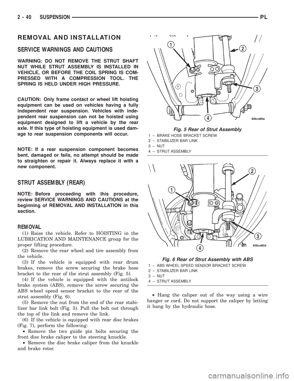
bracket to the rear of the strut assembly (Fig. 5).
(4) If the vehicle is equipped with the antilock
brake system (ABS), remove the screw securing the
ABS wheel speed sensor bracket to the rear of the
strut assembly (Fig. 6).
(5) Remove the nut from the end of the rear stabi-
lizer bar link bolt (Fig. 5). Pull the bolt out through
the top of the link and remove the link.
(6) If the vehicle is equipped with rear disc brakes
(Fig. 7), perform the following:
²Remove the two guide pin bolts securing the
front disc brake caliper to the steering knuckle.
²Remove the disc brake caliper from the knuckle
and brake rotor.²Hang the caliper out of the way using a wire
hanger or cord. Do not support the caliper by letting
it hang by the hydraulic hose.
Fig. 5 Rear of Strut Assembly
1 ± BRAKE HOSE BRACKET SCREW
2 ± STABILIZER BAR LINK
3 ± NUT
4 ± STRUT ASSEMBLY
Fig. 6 Rear of Strut Assembly with ABS
1 ± ABS WHEEL SPEED SENSOR BRACKET SCREW
2 ± STABILIZER BAR LINK
3 ± NUT
4 ± STRUT ASSEMBLY
2 - 40 SUSPENSIONPL
Page 53 of 1285
²Place the link center sleeve and bushings
between the eye in the end of the stabilizer bar and
the link mounting bracket on the strut.
²Start the stabilizer bar link bolt with bushing
from the top, down through the stabilizer bar, inner
link bushings and sleeve, and strut link mounting
bracket.
²Install a lower bushing, then the nut. Do not
tighten the nut at this time.
(8) If the vehicle is equipped with the antilock
brake system (ABS), install the screw securing the
ABS wheel speed sensor bracket to the rear of the
strut assembly (Fig. 6). Tighten the mounting screw
to a torque of 13 N´m (120 in. lbs.).
(9) If the vehicle is equipped with rear drum
brakes, install the screw securing the brake hose
bracket to the rear of the strut assembly (Fig. 5).
Tighten the screw to a torque of 31 N´m (275 in. lbs.).
(10) Install the tire and wheel assembly on vehicle.
Tighten the wheel mounting stud nuts in proper
sequence until all nuts are torqued to half specifica-
tion. Repeat the tightening sequence, this time, to
full specified torque of 135 N´m (100 ft. lbs.).
(11) Lower the vehicle to ground level.
(12) Tighten the stabilizer bar link nut to a torque
of 23 N´m (200 in. lbs.).
(13) Set the rear toe on the vehicle to the required
specification if necessary. Refer to WHEEL ALIGN-
MENT in this service manual group.
KNUCKLE (REAR)
NOTE: Before proceeding with this procedure,
review SERVICE WARNINGS AND CAUTIONS at the
beginning of REMOVAL AND INSTALLATION in this
section.
REMOVAL
(1) Raise the vehicle. Refer to HOISTING in the
LUBRICATION AND MAINTENANCE group for the
proper lifting procedure.
(2) Remove the rear wheel and tire assembly from
the vehicle.
(3) If the vehicle is equipped with rear drum
brakes, remove the screw securing the brake hose
bracket to the rear of the strut assembly (Fig. 5).
(4) If the vehicle is equipped with the antilock
brake system (ABS), remove the screw securing the
ABS wheel speed sensor bracket to the rear of the
strut assembly (Fig. 6).
(5) If the vehicle is equipped with rear drum
brakes, remove any retainer clips from the wheel
mounting studs, then pull the brake drum off the
hub and bearing.
(6) If the vehicle is equipped with rear disc brakes
(Fig. 7), perform the following:²Remove the two guide pin bolts securing the
front disc brake caliper to the steering knuckle.
²Remove the disc brake caliper from the knuckle
and brake rotor.
²Hang the caliper out of the way using a wire
hanger or cord. Do not support the caliper by letting
it hang by the hydraulic hose.
²Remove any retainer clips from the wheel
mounting studs, then pull the brake rotor off the hub
and bearing.
(7) Remove the dust cap from the hub and bearing
assembly (Fig. 7).
(8) Remove the retaining nut, then the hub and
bearing from the knuckle's spindle (Fig. 7).
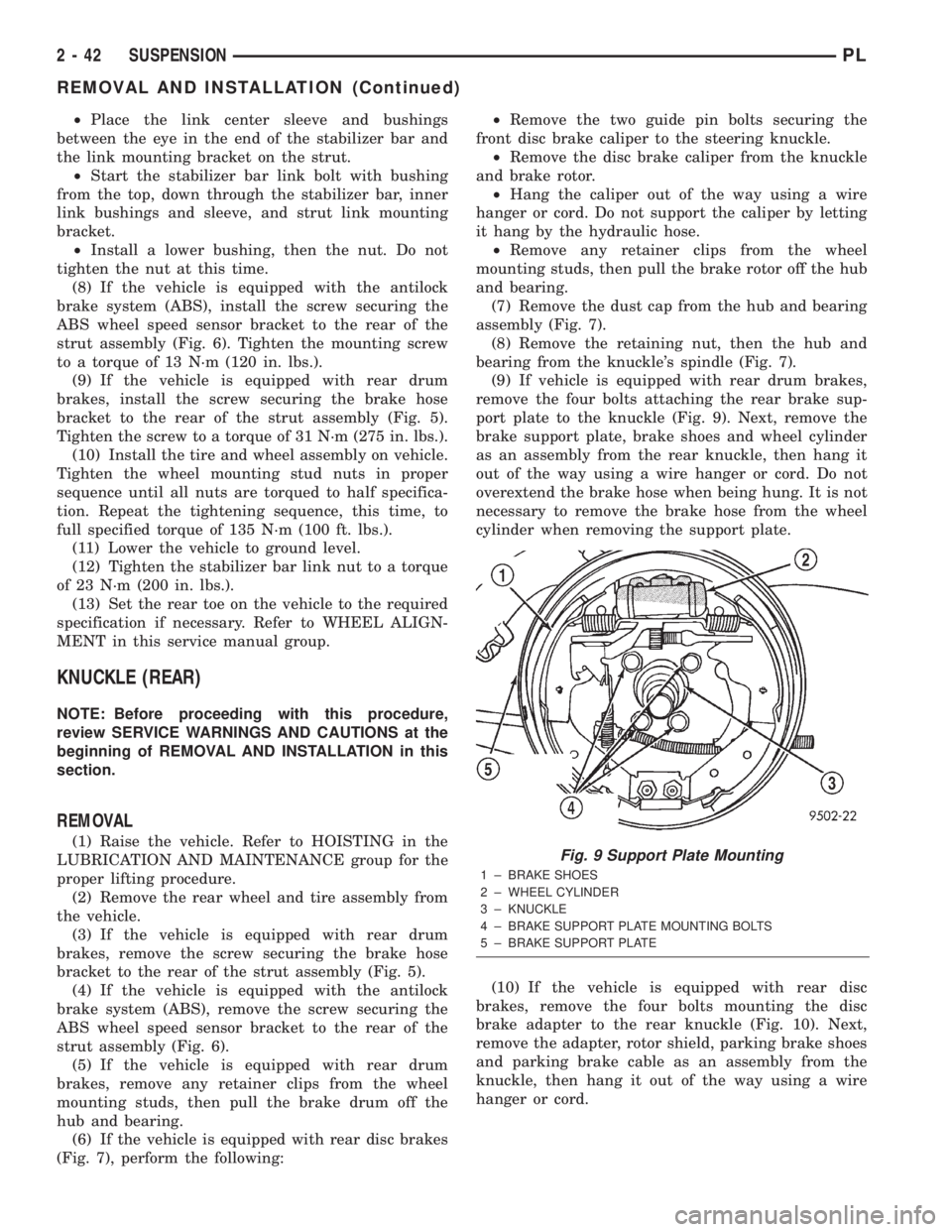
(9) If vehicle is equipped with rear drum brakes,
remove the four bolts attaching the rear brake sup-
port plate to the knuckle (Fig. 9). Next, remove the
brake support plate, brake shoes and wheel cylinder
as an assembly from the rear knuckle, then hang it
out of the way using a wire hanger or cord. Do not
overextend the brake hose when being hung. It is not
necessary to remove the brake hose from the wheel
cylinder when removing the support plate.
(10) If the vehicle is equipped with rear disc
brakes, remove the four bolts mounting the disc
brake adapter to the rear knuckle (Fig. 10). Next,
remove the adapter, rotor shield, parking brake shoes
and parking brake cable as an assembly from the
knuckle, then hang it out of the way using a wire
hanger or cord.Fig. 9 Support Plate Mounting
1 ± BRAKE SHOES
2 ± WHEEL CYLINDER
3 ± KNUCKLE
4 ± BRAKE SUPPORT PLATE MOUNTING BOLTS
5 ± BRAKE SUPPORT PLATE
2 - 42 SUSPENSIONPL
REMOVAL AND INSTALLATION (Continued)
Page 55 of 1285
the front side. Install the nut, but do not completely
tighten it at this time. The nut will need to be tight-
ened when the vehicle is at curb height.
(4) Install the rear bayonet bushing on the tension
strut. Be sure the stepped area of the bushing is
squarely seated into the hole in the knuckle.
(5) Install the rear tension strut retainer, then the
nut. To completely install the nut, place a wrench on
the flat formed into the tension strut and tighten the
nut (Fig. 12). Tighten the nut to a torque of 95 N´m
(70 ft. lbs.).
(6) If vehicle is equipped with rear drum brakes,
install the brake support plate on the knuckle and
attach it using it's four mounting bolts (Fig. 9).
Tighten the mounting bolts to a torque of 75 N´m (55
ft. lbs.).
(7) If the vehicle is equipped with rear disc brakes,
install the disc brake adapter on the knuckle and
attach it using it's four mounting bolts (Fig. 10).
Tighten the mounting bolts to a torque of 75 N´m (55
ft. lbs.).
(8) Install the hub and bearing on the knuckle's
spindle, then install a new retaining nut (Fig. 7). Do
not reuse the original nut. Tighten the nut to a
torque of 217 N´m (160 ft. lbs.).
(9) Install the dust cap on the end of the hub and
bearing (Fig. 7).
(10) If the vehicle is equipped with rear disc
brakes (Fig. 7), install the brake rotor and disc brake
caliper on the knuckle. Install the two guide pin bolts
securing the front disc brake caliper to the steering
knuckle. Tighten the guide pin bolts to a torque of 22
N´m (192 in. lbs.).
(11) If the vehicle is equipped with rear drum
brakes, install the screw securing the brake hose
bracket to the rear of the strut assembly (Fig. 5).
Tighten the screw to a torque of 31 N´m (275 in. lbs.).
(12) If the vehicle is equipped with the antilock
brake system (ABS), install the screw securing the
ABS wheel speed sensor bracket to the rear of the
strut assembly (Fig. 6). Tighten the mounting screw
to a torque of 13 N´m (120 in. lbs.).
(13) Install the tire and wheel assembly. Tighten
the wheel mounting nuts in proper sequence until all
nuts are torqued to half specification. Repeat the
tightening sequence, this time, to full specified
torque of 135 N´m (100 ft. lbs.).
(14) Lower the vehicle to ground level.
(15) Tighten the lateral arm-to-knuckle mounting
bolt nut to a torque of 95 N´m (70 ft. lbs.).
(16) Set the rear toe on the vehicle to the required
specification if necessary. Refer to WHEEL ALIGN-
MENT in this service manual group.HUB AND BEARING (REAR)
NOTE: Before proceeding with this procedure,
review SERVICE WARNINGS AND CAUTIONS at the
beginning of REMOVAL AND INSTALLATION in this
section.
REMOVAL
(1) Raise the vehicle. Refer to HOISTING in the
LUBRICATION AND MAINTENANCE group for the
proper lifting procedure.
(2) Remove the rear wheel and tire assembly from
the vehicle.
(3) If the vehicle is equipped with rear drum
brakes, remove any retainer clips from the wheel
mounting studs, then pull the brake drum off the
hub and bearing.
(4) If the vehicle is equipped with rear disc brakes
(Fig. 7), perform the following:
²Remove the two guide pin bolts securing the
front disc brake caliper to the steering knuckle.
²Remove the disc brake caliper from the knuckle
and brake rotor.
²Hang the caliper out of the way using a wire
hanger or cord. Do not support the caliper by letting
it hang by the hydraulic hose.
²Remove any retainer clips from the wheel
mounting studs, then pull the brake rotor off the hub
and bearing.
(5) Remove the dust cap from the hub and bearing
assembly (Fig. 7).
(6) Remove the retaining nut, then the hub and
bearing from the knuckle's spindle (Fig. 7).
INSTALLATION
(1) Install the hub and bearing on the knuckle's
spindle, then install a new retaining nut (Fig. 7). Do
not reuse the original nut. Tighten the nut to a
torque of 217 N´m (160 ft. lbs.).
(2) Install the dust cap on the end of the hub and
bearing (Fig. 7).
(3) If the vehicle is equipped with rear disc brakes
(Fig. 7), install the brake rotor and disc brake caliper
on the knuckle. Install the two guide pin bolts secur-
ing the front disc brake caliper to the steering
knuckle. Tighten the guide pin bolts to a torque of 22
N´m (192 in. lbs.).
(4) Install the tire and wheel assembly. Tighten
the wheel mounting nuts in proper sequence until all
nuts are torqued to half specification. Repeat the
tightening sequence, this time, to full specified
torque of 135 N´m (100 ft. lbs.).
(5) Lower the vehicle to ground level.
2 - 44 SUSPENSIONPL
REMOVAL AND INSTALLATION (Continued)
Page 64 of 1285
SHUDDER OR VIBRATION DURING ACCELERATION
(1) A worn or damaged driveshaft inner tripod
joint.
(2) A sticking tripod joint spider assembly (inner
tripod joint only).
(3) Improper wheel alignment. See Wheel Align-
ment in this group for alignment checking and set-
ting procedures and specifications.
VIBRATION AT HIGHWAY SPEEDS
(1) Foreign material (mud, etc.) packed on the
backside of the wheel(s).
(2) Out of balance front tires or wheels. See Group
22, Wheels And Tires for the required balancing pro-
cedure.
(3) Improper tire and/or wheel runout. See Group
22, Wheels And Tires for the required runout check-
ing procedure.
REMOVAL AND INSTALLATION
DRIVESHAFTS
CAUTION: Boot sealing is vital to retain special
lubricants and to prevent foreign contaminants
from entering the C/V joint. Mishandling, such as
allowing the assemblies to dangle unsupported, or
pulling or pushing the ends can cut boots or dam-
age C/V joints. During removal and installation pro-
cedures, always support both ends of the driveshaft
to prevent damage.
REMOVAL
CAUTION: The driveshaft, when installed, acts as a
bolt and secures the front hub/bearing assembly. If
vehicle is to be supported or moved on its wheels
with a driveshaft removed, install a PROPER±SIZED
BOLT AND NUT through front hub. Tighten bolt and
nut to 203 N´m (150 ft. lbs.). This will ensure that
the hub bearing cannot loosen.
(1) Disconnect battery negative cable.
(2) Place transaxle in gated park.
(3) Raise vehicle on hoist.
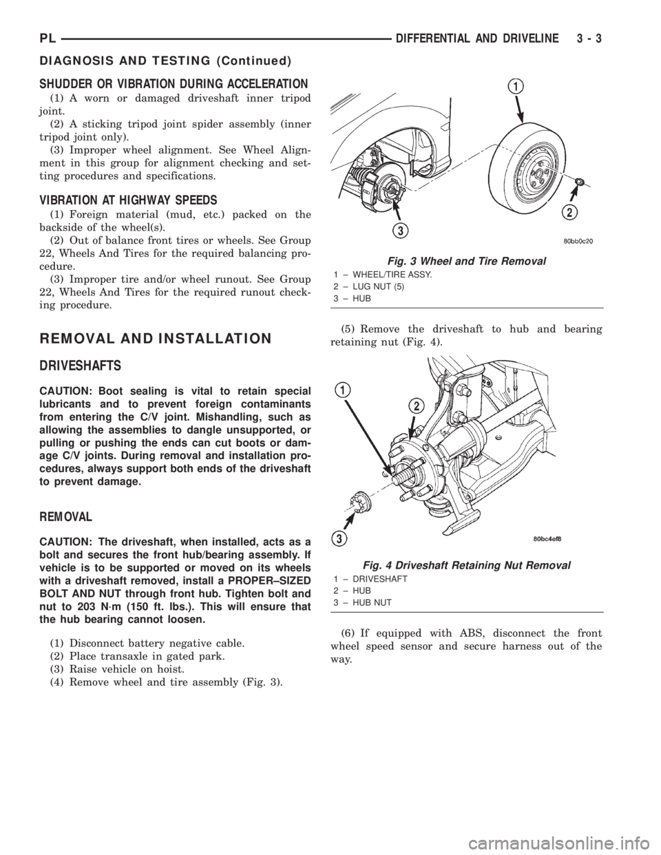
(4) Remove wheel and tire assembly (Fig. 3).(5) Remove the driveshaft to hub and bearing
retaining nut (Fig. 4).
(6) If equipped with ABS, disconnect the front
wheel speed sensor and secure harness out of the
way.
Fig. 3 Wheel and Tire Removal
1 ± WHEEL/TIRE ASSY.
2 ± LUG NUT (5)
3 ± HUB
Fig. 4 Driveshaft Retaining Nut Removal
1 ± DRIVESHAFT
2 ± HUB
3 ± HUB NUT
PLDIFFERENTIAL AND DRIVELINE 3 - 3
DIAGNOSIS AND TESTING (Continued)
Page 81 of 1285
DESCRIPTION AND OPERATION
BASE BRAKE SYSTEM OPERATION
When a vehicle needs to be stopped, the driver
applies the brake pedal. The brake pedal pushes the
input rod of the power brake booster into the booster.
The booster uses vacuum to ease pedal effort as force
is transferred through the booster to the master cyl-
inder. The booster's output rod pushes in the master
cylinder's primary and secondary pistons applying
hydraulic pressure through the chassis brake tubes
and proportioning valves (rear only) to the brakes at
each tire and wheel assembly.
Front disc brakes control the braking of the front
wheels; rear braking is controlled by rear drum
brakes as standard equipment. Rear disc brakes and
an antilock brake system (ABS) with traction control
are optional.
The hydraulic brake system is diagonally split on
both the non-antilock and antilock braking systems.
This means the left front and right rear brakes are
on one hydraulic circuit and the right front and left
rear are on the other.
Vehicles equipped with the optional antilock brake
system (ABS) use a system designated Mark 20e.
This system shares most base brake hardware used
on vehicles without ABS. A vehicle equipped with
ABS, however, uses a different master cylinder and
brake tubes. Also included in the ABS system is an
integrated control unit (ICU) and four wheel speed
sensors. These components are described in detail in
the ANTILOCK BRAKE SYSTEM section in this
group of the service manual. All vehicles with ABS
come standard with four-wheel-disc brakes and trac-
tion control.
The parking brakes are hand-operated. When
applied, the parking brake lever pulls on cables that
actuate brake shoes at each rear wheel. The parking
brake lever has an automatic adjusting feature that
takes up any excessive slack in the parking brake
cable system.
BASE BRAKE SYSTEM COMPONENTS
BRAKE PEDAL
A suspended-type brake pedal is used on this vehi-
cle. The pedal pivots on a shaft mounted in the pedal
support bracket under the instrument panel. The
pedal connects to the power brake booster input rod
and pushes it in when the pedal is applied.
The brake pedal and it's pad are serviceable sepa-
rately.
POWER BRAKE BOOSTER
There are two different power brake booster
designs, although externally they appear the same.
All vehicles use a 205 mm tandem diaphragm power
brake booster. The two boosters are internally tuned
differently depending on whether the vehicle is
equipped with the standard front disc/rear drum
brake combination or the optional front disc/rear disc
(four-wheel disc) brake combination. If the power
brake booster requires replacement, be sure it is
replaced with the correct part.
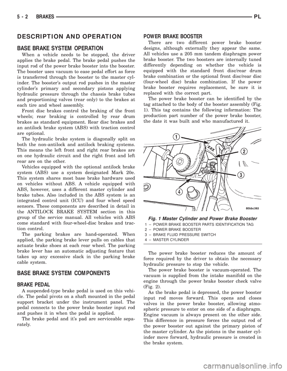
The power brake booster can be identified by the
tag attached to the body of the booster assembly (Fig.
1). This tag contains the following information: The
production part number of the power brake booster,
the date it was built and who manufactured it.
The power brake booster reduces the amount of
force required by the driver to obtain the necessary
hydraulic pressure to stop the vehicle.
The power brake booster is vacuum-operated. The
vacuum is supplied from the intake manifold on the
engine through the power brake booster check valve
(Fig. 2).
As the brake pedal is depressed, the power booster
input rod moves forward. This opens and closes
valves in the power brake booster, allowing atmo-
spheric pressure to enter on one side of a diaphragm.
Engine vacuum is always present on the other side.
This difference in pressure forces the output rod of
the power booster out against the primary piston of
the master cylinder. As the pistons in the master cyl-
inder move forward, hydraulic pressure is created in
the brake system.
Fig. 1 Master Cylinder and Power Brake Booster
1 ± POWER BRAKE BOOSTER PARTS IDENTIFICATION TAG
2 ± POWER BRAKE BOOSTER
3 ± BRAKE FLUID PRESSURE SWITCH
4 ± MASTER CYLINDER
5 - 2 BRAKESPL