2000 DODGE NEON sensor
[x] Cancel search: sensorPage 162 of 1285
WHEEL SPEED SENSOR (REAR)
NOTE: Before proceeding with this procedure,
review SERVICE WARNINGS AND CAUTIONS at the
beginning of REMOVAL AND INSTALLATION in this
section.
REMOVAL
(1) Raise the vehicle. Refer to HOISTING in the
LUBRICATION AND MAINTENANCE group for the
proper lifting procedure.
(2) Remove the tire and wheel assembly from the
vehicle.
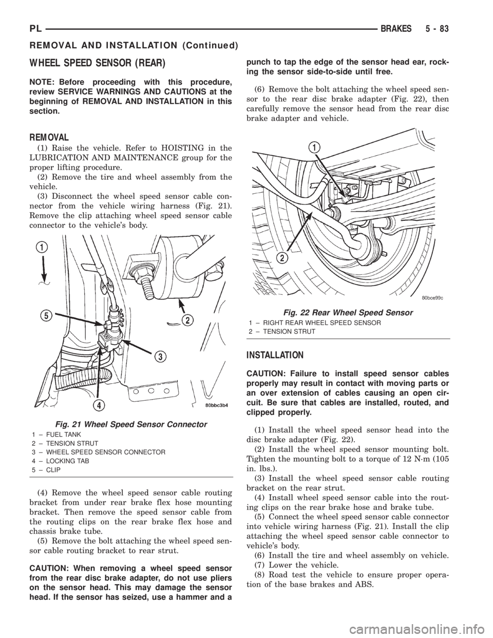
(3) Disconnect the wheel speed sensor cable con-
nector from the vehicle wiring harness (Fig. 21).
Remove the clip attaching wheel speed sensor cable
connector to the vehicle's body.
(4) Remove the wheel speed sensor cable routing
bracket from under rear brake flex hose mounting
bracket. Then remove the speed sensor cable from
the routing clips on the rear brake flex hose and
chassis brake tube.
(5) Remove the bolt attaching the wheel speed sen-
sor cable routing bracket to rear strut.
CAUTION: When removing a wheel speed sensor
from the rear disc brake adapter, do not use pliers
on the sensor head. This may damage the sensor
head. If the sensor has seized, use a hammer and apunch to tap the edge of the sensor head ear, rock-
ing the sensor side-to-side until free.
(6) Remove the bolt attaching the wheel speed sen-
sor to the rear disc brake adapter (Fig. 22), then
carefully remove the sensor head from the rear disc
brake adapter and vehicle.
INSTALLATION
CAUTION: Failure to install speed sensor cables
properly may result in contact with moving parts or
an over extension of cables causing an open cir-
cuit. Be sure that cables are installed, routed, and
clipped properly.
(1) Install the wheel speed sensor head into the
disc brake adapter (Fig. 22).
(2) Install the wheel speed sensor mounting bolt.
Tighten the mounting bolt to a torque of 12 N´m (105
in. lbs.).
(3) Install the wheel speed sensor cable routing
bracket on the rear strut.
(4) Install wheel speed sensor cable into the rout-
ing clips on the rear brake hose and brake tube.
(5) Connect the wheel speed sensor cable connector
into vehicle wiring harness (Fig. 21). Install the clip
attaching the wheel speed sensor cable connector to
vehicle's body.
(6) Install the tire and wheel assembly on vehicle.
(7) Lower the vehicle.
(8) Road test the vehicle to ensure proper opera-
tion of the base brakes and ABS.
Fig. 21 Wheel Speed Sensor Connector
1 ± FUEL TANK
2 ± TENSION STRUT
3 ± WHEEL SPEED SENSOR CONNECTOR
4 ± LOCKING TAB
5 ± CLIP
Fig. 22 Rear Wheel Speed Sensor
1 ± RIGHT REAR WHEEL SPEED SENSOR
2 ± TENSION STRUT
PLBRAKES 5 - 83
REMOVAL AND INSTALLATION (Continued)
Page 164 of 1285
SPECIFICATIONS
TONE WHEEL RUNOUT
FRONT TONE WHEEL:
Maximum Runout.........0.25 mm (0.009 in.)
REAR TONE WHEEL:
Maximum Runout.........0.25 mm (0.009 in.)
WHEEL SPEED SENSOR-TO-TONE WHEEL
CLEARANCE
FRONT WHEEL:
Minimum Clearance.......0.28 mm (0.011 in.)
Maximum Clearance.......1.42 mm (0.056 in.)
REAR WHEEL:
Minimum Clearance.......0.45 mm (0.018 in.)
Maximum Clearance.......1.12 mm (0.044 in.)
BRAKE FASTENER TORQUE SPECIFICATIONS
DESCRIPTION TORQUE
BRAKE TUBES:
Tube Nuts............... 17N´m(145 in. lbs.)
MASTER CYLINDER:
Mounting Nuts.......... 28N´m(250 in. lbs.)
POWER BRAKE BOOSTER:
Mounting Nuts.......... 34N´m(300 in. lbs.)
DISC BRAKE CALIPER:
Caliper Banjo Bolt......... 48N´m(35ft.lbs.)
Guide Pin Bolts.......... 22N´m(192 in. lbs.)
Bleeder Screw........... 15N´m(125 in. lbs.)
WHEEL CYLINDER (REAR):
Mounting Bolts.......... 13N´m(115in.lbs.)
Bleeder Screw............ 10N´m(80in.lbs.)
DRUM BRAKE SHOE SUPPORT PLATE
(REAR):
Mounting Bolts........... 75N´m(55ft.lbs.)
DISC BRAKE ADAPTER (REAR):
Mounting Bolts........... 75N´m(55ft.lbs.)
HUB AND BEARING (REAR):
Retaining Nut.......... 217N´m(160 ft. lbs.)
PARKING BRAKE:
Lever Mounting Nuts..... 28N´m(250 in. lbs.)
TIRE AND WHEEL:
Wheel Mounting Nut...........109±150 N´m
(80±110 ft. lbs.)
INTEGRATED CONTROL UNIT:
Mounting Bolts........... 11N´m(97in.lbs.)
CAB Mounting bolts........ 2N´m(17in.lbs.)
Bracket-to-Frame Rail Bolts.......... 23N´m
(200 in. lbs.)
WHEEL SPEED SENSOR:
Head Mounting bolt...... 12N´m(105 in. lbs.)
PLBRAKES 5 - 85
Page 173 of 1285
housing does not move, it is improperly installed or
defective.
(3) Route cable to the transaxle and connect cable
end to the clutch release lever and transaxle housing
(Fig. 7).
(4) Install bellhousing cap (Fig. 7).
(5) Install and fasten battery tray.
(6) Install battery and hold-down clamp.
(7) Connect both battery cables.
(8) Verify that the clutch cable is working properly.
CLUTCH INTERLOCK/UPSTOP SWITCH
REMOVAL
(1) Disconnect and isolate battery negative cable.
(2) Remove instrument panel assembly. Refer to
Group 8E, Instrument Panel and Systems for the
proper procedure.
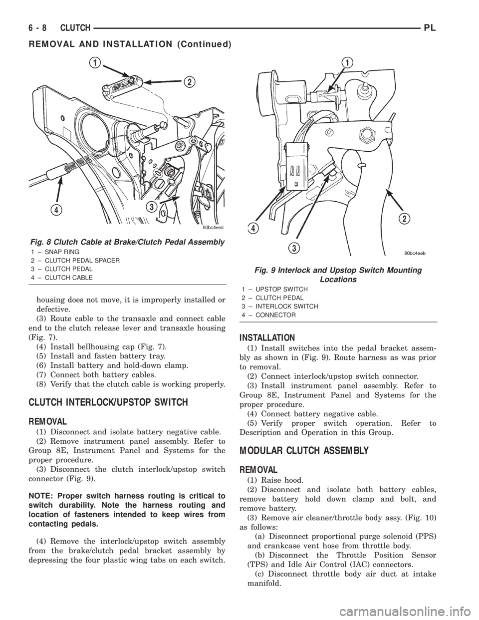
(3) Disconnect the clutch interlock/upstop switch
connector (Fig. 9).
NOTE: Proper switch harness routing is critical to
switch durability. Note the harness routing and
location of fasteners intended to keep wires from
contacting pedals.
(4) Remove the interlock/upstop switch assembly
from the brake/clutch pedal bracket assembly by
depressing the four plastic wing tabs on each switch.
INSTALLATION
(1) Install switches into the pedal bracket assem-
bly as shown in (Fig. 9). Route harness as was prior
to removal.
(2) Connect interlock/upstop switch connector.
(3) Install instrument panel assembly. Refer to
Group 8E, Instrument Panel and Systems for the
proper procedure.
(4) Connect battery negative cable.
(5) Verify proper switch operation. Refer to
Description and Operation in this Group.
MODULAR CLUTCH ASSEMBLY
REMOVAL
(1) Raise hood.
(2) Disconnect and isolate both battery cables,
remove battery hold down clamp and bolt, and
remove battery.
(3) Remove air cleaner/throttle body assy. (Fig. 10)
as follows:
(a) Disconnect proportional purge solenoid (PPS)
and crankcase vent hose from throttle body.
(b) Disconnect the Throttle Position Sensor
(TPS) and Idle Air Control (IAC) connectors.
(c) Disconnect throttle body air duct at intake
manifold.
Fig. 8 Clutch Cable at Brake/Clutch Pedal Assembly
1 ± SNAP RING
2 ± CLUTCH PEDAL SPACER
3 ± CLUTCH PEDAL
4 ± CLUTCH CABLE
Fig. 9 Interlock and Upstop Switch Mounting
Locations
1 ± UPSTOP SWITCH
2 ± CLUTCH PEDAL
3 ± INTERLOCK SWITCH
4 ± CONNECTOR
6 - 8 CLUTCHPL
REMOVAL AND INSTALLATION (Continued)
Page 174 of 1285
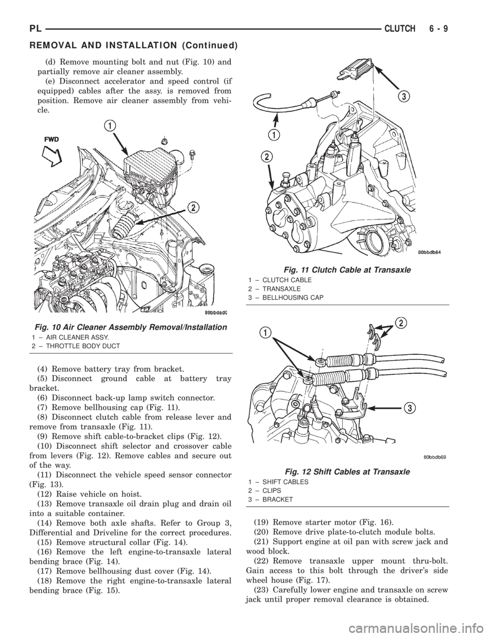
(d) Remove mounting bolt and nut (Fig. 10) and
partially remove air cleaner assembly.
(e) Disconnect accelerator and speed control (if
equipped) cables after the assy. is removed from
position. Remove air cleaner assembly from vehi-
cle.
(4) Remove battery tray from bracket.
(5) Disconnect ground cable at battery tray
bracket.
(6) Disconnect back-up lamp switch connector.
(7) Remove bellhousing cap (Fig. 11).
(8) Disconnect clutch cable from release lever and
remove from transaxle (Fig. 11).
(9) Remove shift cable-to-bracket clips (Fig. 12).
(10) Disconnect shift selector and crossover cable
from levers (Fig. 12). Remove cables and secure out
of the way.
(11) Disconnect the vehicle speed sensor connector
(Fig. 13).
(12) Raise vehicle on hoist.
(13) Remove transaxle oil drain plug and drain oil
into a suitable container.
(14) Remove both axle shafts. Refer to Group 3,
Differential and Driveline for the correct procedures.
(15) Remove structural collar (Fig. 14).
(16) Remove the left engine-to-transaxle lateral
bending brace (Fig. 14).
(17) Remove bellhousing dust cover (Fig. 14).
(18) Remove the right engine-to-transaxle lateral
bending brace (Fig. 15).(19) Remove starter motor (Fig. 16).
(20) Remove drive plate-to-clutch module bolts.
(21) Support engine at oil pan with screw jack and
wood block.
(22) Remove transaxle upper mount thru-bolt.
Gain access to this bolt through the driver's side
wheel house (Fig. 17).
(23) Carefully lower engine and transaxle on screw
jack until proper removal clearance is obtained.
Fig. 10 Air Cleaner Assembly Removal/Installation
1 ± AIR CLEANER ASSY.
2 ± THROTTLE BODY DUCTFWD
Fig. 11 Clutch Cable at Transaxle
1 ± CLUTCH CABLE
2 ± TRANSAXLE
3 ± BELLHOUSING CAP
Fig. 12 Shift Cables at Transaxle
1 ± SHIFT CABLES
2 ± CLIPS
3 ± BRACKET
PLCLUTCH 6 - 9
REMOVAL AND INSTALLATION (Continued)
Page 175 of 1285
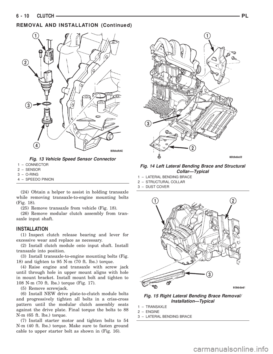
(24) Obtain a helper to assist in holding transaxle
while removing transaxle-to-engine mounting bolts
(Fig. 18).
(25) Remove transaxle from vehicle (Fig. 18).
(26) Remove modular clutch assembly from tran-
saxle input shaft.
INSTALLATION
(1) Inspect clutch release bearing and lever for
excessive wear and replace as necessary.
(2) Install clutch module onto input shaft. Install
transaxle into position.
(3) Install transaxle-to-engine mounting bolts (Fig.
18) and tighten to 95 N´m (70 ft. lbs.) torque.
(4) Raise engine and transaxle with screw jack
until through hole in upper mount aligns with hole
in mount bracket. Install mount bolt and tighten to
108 N´m (70 ft. lbs.) torque (Fig. 17).
(5) Remove screwjack.
(6) Install NEW drive plate-to-clutch module bolts
and progressively tighten all bolts in a criss-cross
pattern until the modular clutch assembly seats
against the drive plate. Final torque the bolts to 88
N´m (65 ft. lbs.) torque.
(7) Install starter motor and tighten bolts to 54
N´m (40 ft. lbs.) torque. Make sure to fasten ground
cable to upper starter bolt as shown in (Fig. 16).
Fig. 13 Vehicle Speed Sensor Connector
1 ± CONNECTOR
2 ± SENSOR
3 ± O-RING
4 ± SPEEDO PINIONFig. 14 Left Lateral Bending Brace and Structural
CollarÐTypical
1 ± LATERAL BENDING BRACE
2 ± STRUCTURAL COLLAR
3 ± DUST COVER
Fig. 15 Right Lateral Bending Brace Removal/
InstallationÐTypical
1 ± TRANSAXLE
2 ± ENGINE
3 ± LATERAL BENDING BRACE
6 - 10 CLUTCHPL
REMOVAL AND INSTALLATION (Continued)
Page 176 of 1285
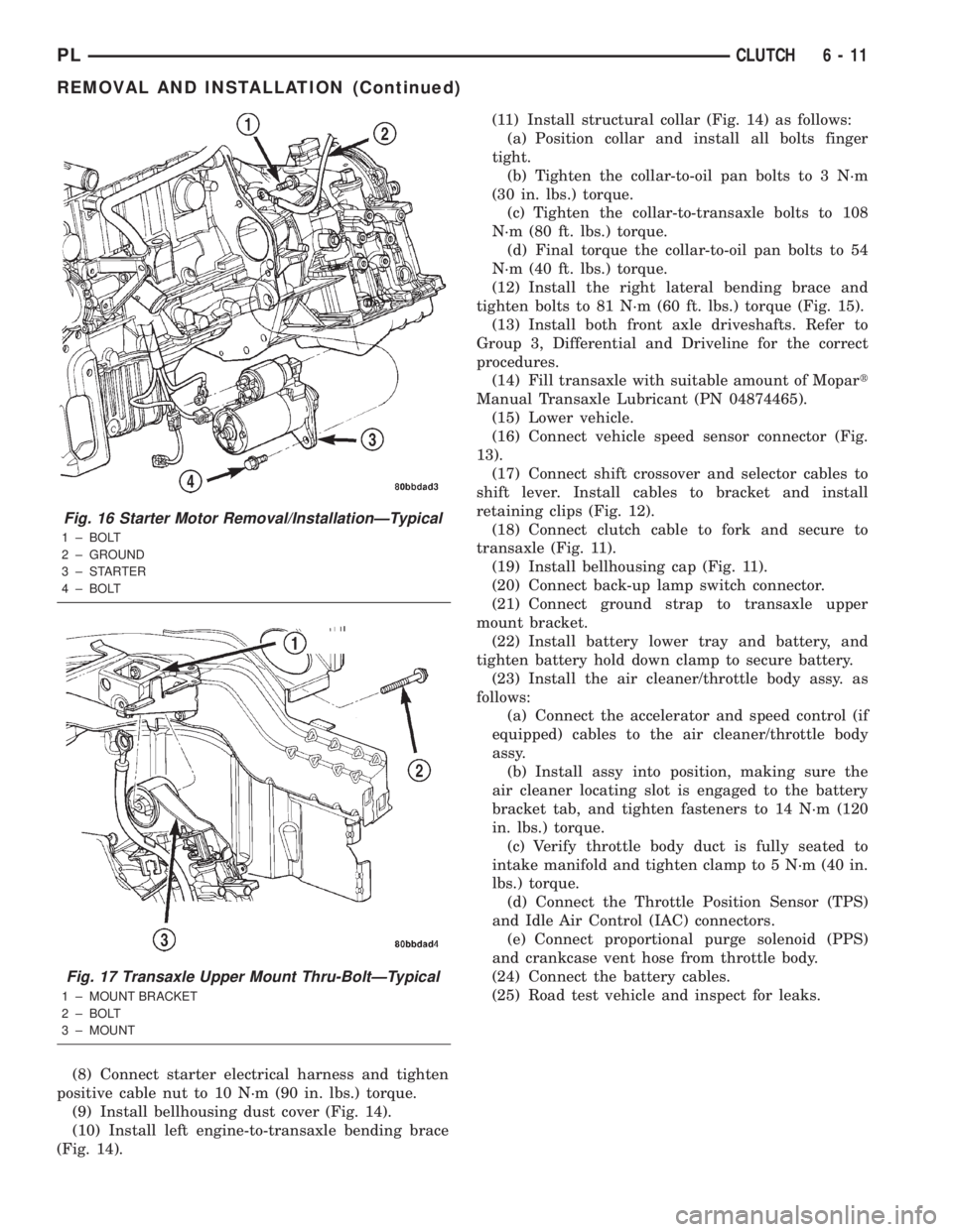
(8) Connect starter electrical harness and tighten
positive cable nut to 10 N´m (90 in. lbs.) torque.
(9) Install bellhousing dust cover (Fig. 14).
(10) Install left engine-to-transaxle bending brace
(Fig. 14).(11) Install structural collar (Fig. 14) as follows:
(a) Position collar and install all bolts finger
tight.
(b) Tighten the collar-to-oil pan bolts to 3 N´m
(30 in. lbs.) torque.
(c) Tighten the collar-to-transaxle bolts to 108
N´m (80 ft. lbs.) torque.
(d) Final torque the collar-to-oil pan bolts to 54
N´m (40 ft. lbs.) torque.
(12) Install the right lateral bending brace and
tighten bolts to 81 N´m (60 ft. lbs.) torque (Fig. 15).
(13) Install both front axle driveshafts. Refer to
Group 3, Differential and Driveline for the correct
procedures.
(14) Fill transaxle with suitable amount of Mopart
Manual Transaxle Lubricant (PN 04874465).
(15) Lower vehicle.
(16) Connect vehicle speed sensor connector (Fig.
13).
(17) Connect shift crossover and selector cables to
shift lever. Install cables to bracket and install
retaining clips (Fig. 12).
(18) Connect clutch cable to fork and secure to
transaxle (Fig. 11).
(19) Install bellhousing cap (Fig. 11).
(20) Connect back-up lamp switch connector.
(21) Connect ground strap to transaxle upper
mount bracket.
(22) Install battery lower tray and battery, and
tighten battery hold down clamp to secure battery.
(23) Install the air cleaner/throttle body assy. as
follows:
(a) Connect the accelerator and speed control (if
equipped) cables to the air cleaner/throttle body
assy.
(b) Install assy into position, making sure the
air cleaner locating slot is engaged to the battery
bracket tab, and tighten fasteners to 14 N´m (120
in. lbs.) torque.
(c) Verify throttle body duct is fully seated to
intake manifold and tighten clamp to 5 N´m (40 in.
lbs.) torque.
(d) Connect the Throttle Position Sensor (TPS)
and Idle Air Control (IAC) connectors.
(e) Connect proportional purge solenoid (PPS)
and crankcase vent hose from throttle body.
(24) Connect the battery cables.
(25) Road test vehicle and inspect for leaks.
Fig. 16 Starter Motor Removal/InstallationÐTypical
1 ± BOLT
2 ± GROUND
3±STARTER
4 ± BOLT
Fig. 17 Transaxle Upper Mount Thru-BoltÐTypical
1 ± MOUNT BRACKET
2 ± BOLT
3 ± MOUNT
PLCLUTCH 6 - 11
REMOVAL AND INSTALLATION (Continued)
Page 186 of 1285
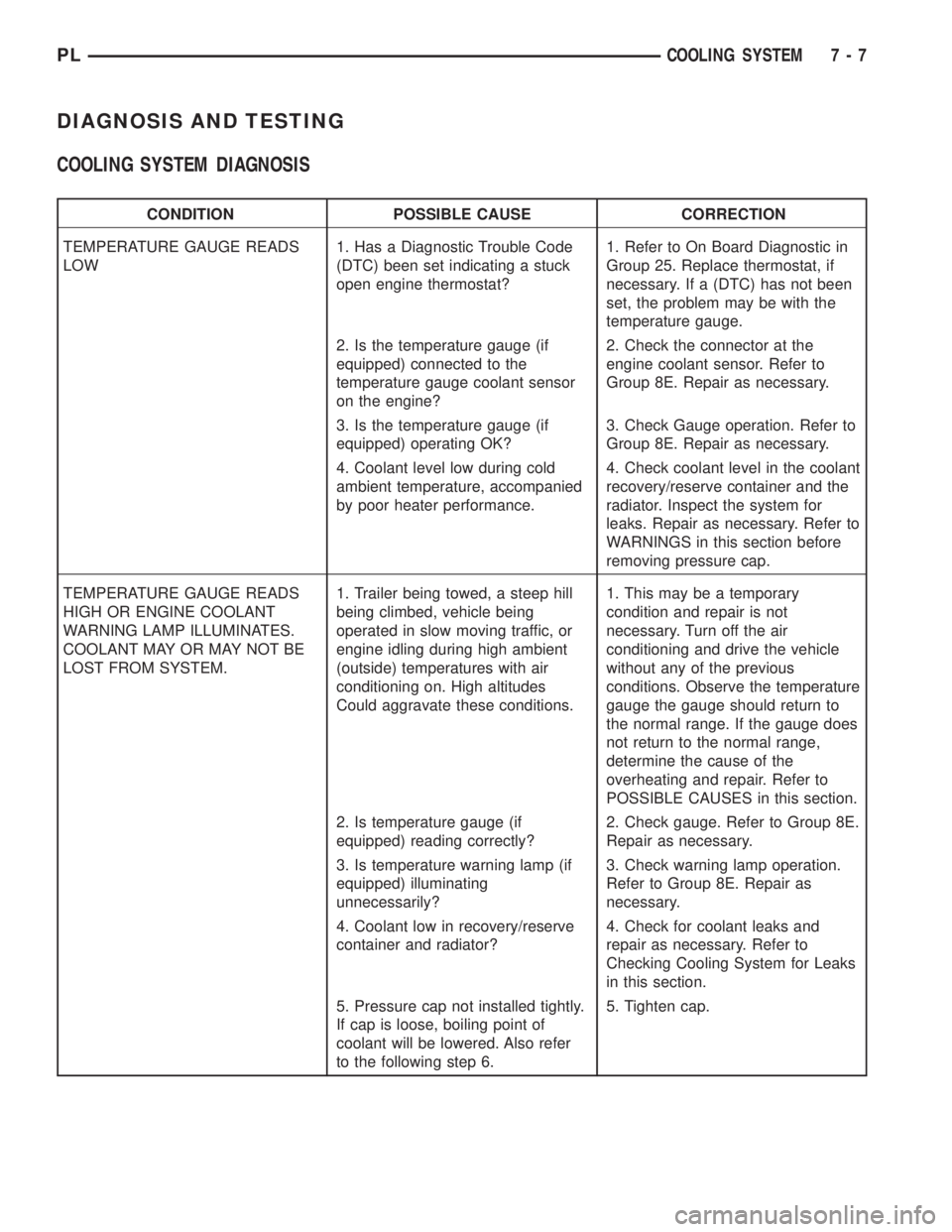
DIAGNOSIS AND TESTING
COOLING SYSTEM DIAGNOSIS
CONDITION POSSIBLE CAUSE CORRECTION
TEMPERATURE GAUGE READS
LOW1. Has a Diagnostic Trouble Code
(DTC) been set indicating a stuck
open engine thermostat?1. Refer to On Board Diagnostic in
Group 25. Replace thermostat, if
necessary. If a (DTC) has not been
set, the problem may be with the
temperature gauge.
2. Is the temperature gauge (if
equipped) connected to the
temperature gauge coolant sensor
on the engine?2. Check the connector at the
engine coolant sensor. Refer to
Group 8E. Repair as necessary.
3. Is the temperature gauge (if
equipped) operating OK?3. Check Gauge operation. Refer to
Group 8E. Repair as necessary.
4. Coolant level low during cold
ambient temperature, accompanied
by poor heater performance.4. Check coolant level in the coolant
recovery/reserve container and the
radiator. Inspect the system for
leaks. Repair as necessary. Refer to
WARNINGS in this section before
removing pressure cap.
TEMPERATURE GAUGE READS
HIGH OR ENGINE COOLANT
WARNING LAMP ILLUMINATES.
COOLANT MAY OR MAY NOT BE
LOST FROM SYSTEM.1. Trailer being towed, a steep hill
being climbed, vehicle being
operated in slow moving traffic, or
engine idling during high ambient
(outside) temperatures with air
conditioning on. High altitudes
Could aggravate these conditions.1. This may be a temporary
condition and repair is not
necessary. Turn off the air
conditioning and drive the vehicle
without any of the previous
conditions. Observe the temperature
gauge the gauge should return to
the normal range. If the gauge does
not return to the normal range,
determine the cause of the
overheating and repair. Refer to
POSSIBLE CAUSES in this section.
2. Is temperature gauge (if
equipped) reading correctly?2. Check gauge. Refer to Group 8E.
Repair as necessary.
3. Is temperature warning lamp (if
equipped) illuminating
unnecessarily?3. Check warning lamp operation.
Refer to Group 8E. Repair as
necessary.
4. Coolant low in recovery/reserve
container and radiator?4. Check for coolant leaks and
repair as necessary. Refer to
Checking Cooling System for Leaks
in this section.
5. Pressure cap not installed tightly.
If cap is loose, boiling point of
coolant will be lowered. Also refer
to the following step 6.5. Tighten cap.
PLCOOLING SYSTEM 7 - 7
Page 188 of 1285
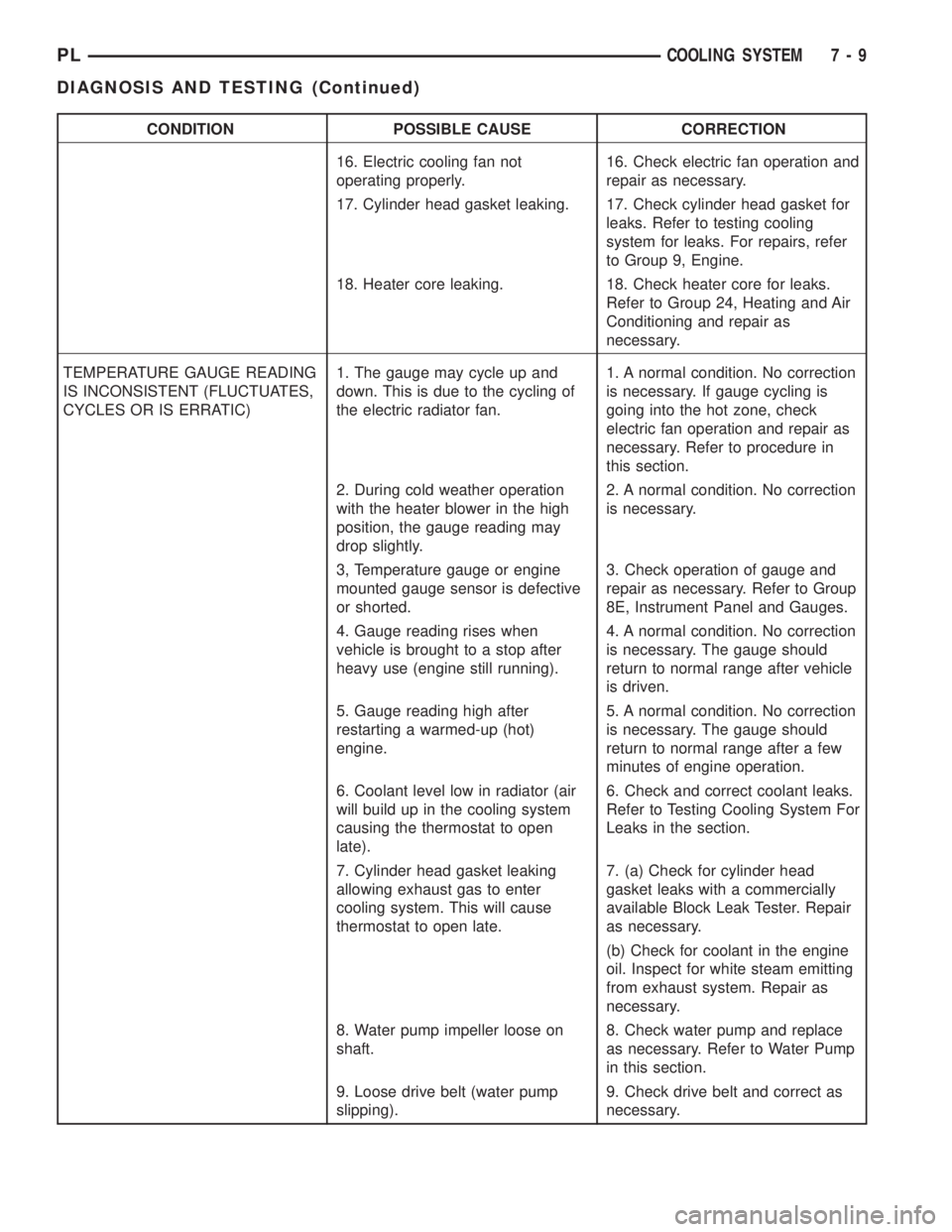
CONDITION POSSIBLE CAUSE CORRECTION
16. Electric cooling fan not
operating properly.16. Check electric fan operation and
repair as necessary.
17. Cylinder head gasket leaking. 17. Check cylinder head gasket for
leaks. Refer to testing cooling
system for leaks. For repairs, refer
to Group 9, Engine.
18. Heater core leaking. 18. Check heater core for leaks.
Refer to Group 24, Heating and Air
Conditioning and repair as
necessary.
TEMPERATURE GAUGE READING
IS INCONSISTENT (FLUCTUATES,
CYCLES OR IS ERRATIC)1. The gauge may cycle up and
down. This is due to the cycling of
the electric radiator fan.1. A normal condition. No correction
is necessary. If gauge cycling is
going into the hot zone, check
electric fan operation and repair as
necessary. Refer to procedure in
this section.
2. During cold weather operation
with the heater blower in the high
position, the gauge reading may
drop slightly.2. A normal condition. No correction
is necessary.
3, Temperature gauge or engine
mounted gauge sensor is defective
or shorted.3. Check operation of gauge and
repair as necessary. Refer to Group
8E, Instrument Panel and Gauges.
4. Gauge reading rises when
vehicle is brought to a stop after
heavy use (engine still running).4. A normal condition. No correction
is necessary. The gauge should
return to normal range after vehicle
is driven.
5. Gauge reading high after
restarting a warmed-up (hot)
engine.5. A normal condition. No correction
is necessary. The gauge should
return to normal range after a few
minutes of engine operation.
6. Coolant level low in radiator (air
will build up in the cooling system
causing the thermostat to open
late).6. Check and correct coolant leaks.
Refer to Testing Cooling System For
Leaks in the section.
7. Cylinder head gasket leaking
allowing exhaust gas to enter
cooling system. This will cause
thermostat to open late.7. (a) Check for cylinder head
gasket leaks with a commercially
available Block Leak Tester. Repair
as necessary.
(b) Check for coolant in the engine
oil. Inspect for white steam emitting
from exhaust system. Repair as
necessary.
8. Water pump impeller loose on
shaft.8. Check water pump and replace
as necessary. Refer to Water Pump
in this section.
9. Loose drive belt (water pump
slipping).9. Check drive belt and correct as
necessary.
PLCOOLING SYSTEM 7 - 9
DIAGNOSIS AND TESTING (Continued)