2000 DODGE NEON parking sensors
[x] Cancel search: parking sensorsPage 81 of 1285

DESCRIPTION AND OPERATION
BASE BRAKE SYSTEM OPERATION
When a vehicle needs to be stopped, the driver
applies the brake pedal. The brake pedal pushes the
input rod of the power brake booster into the booster.
The booster uses vacuum to ease pedal effort as force
is transferred through the booster to the master cyl-
inder. The booster's output rod pushes in the master
cylinder's primary and secondary pistons applying
hydraulic pressure through the chassis brake tubes
and proportioning valves (rear only) to the brakes at
each tire and wheel assembly.
Front disc brakes control the braking of the front
wheels; rear braking is controlled by rear drum
brakes as standard equipment. Rear disc brakes and
an antilock brake system (ABS) with traction control
are optional.
The hydraulic brake system is diagonally split on
both the non-antilock and antilock braking systems.
This means the left front and right rear brakes are
on one hydraulic circuit and the right front and left
rear are on the other.
Vehicles equipped with the optional antilock brake
system (ABS) use a system designated Mark 20e.
This system shares most base brake hardware used
on vehicles without ABS. A vehicle equipped with
ABS, however, uses a different master cylinder and
brake tubes. Also included in the ABS system is an
integrated control unit (ICU) and four wheel speed
sensors. These components are described in detail in
the ANTILOCK BRAKE SYSTEM section in this
group of the service manual. All vehicles with ABS
come standard with four-wheel-disc brakes and trac-
tion control.
The parking brakes are hand-operated. When
applied, the parking brake lever pulls on cables that
actuate brake shoes at each rear wheel. The parking
brake lever has an automatic adjusting feature that
takes up any excessive slack in the parking brake
cable system.
BASE BRAKE SYSTEM COMPONENTS
BRAKE PEDAL
A suspended-type brake pedal is used on this vehi-
cle. The pedal pivots on a shaft mounted in the pedal
support bracket under the instrument panel. The
pedal connects to the power brake booster input rod
and pushes it in when the pedal is applied.
The brake pedal and it's pad are serviceable sepa-
rately.
POWER BRAKE BOOSTER
There are two different power brake booster
designs, although externally they appear the same.
All vehicles use a 205 mm tandem diaphragm power
brake booster. The two boosters are internally tuned
differently depending on whether the vehicle is
equipped with the standard front disc/rear drum
brake combination or the optional front disc/rear disc
(four-wheel disc) brake combination. If the power
brake booster requires replacement, be sure it is
replaced with the correct part.
The power brake booster can be identified by the
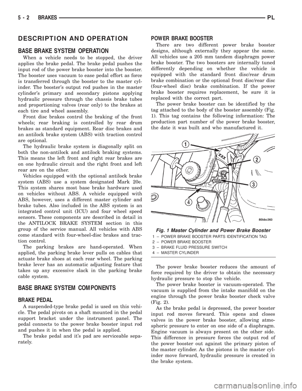
tag attached to the body of the booster assembly (Fig.
1). This tag contains the following information: The
production part number of the power brake booster,
the date it was built and who manufactured it.
The power brake booster reduces the amount of
force required by the driver to obtain the necessary
hydraulic pressure to stop the vehicle.
The power brake booster is vacuum-operated. The
vacuum is supplied from the intake manifold on the
engine through the power brake booster check valve
(Fig. 2).
As the brake pedal is depressed, the power booster
input rod moves forward. This opens and closes
valves in the power brake booster, allowing atmo-
spheric pressure to enter on one side of a diaphragm.
Engine vacuum is always present on the other side.
This difference in pressure forces the output rod of
the power booster out against the primary piston of
the master cylinder. As the pistons in the master cyl-
inder move forward, hydraulic pressure is created in
the brake system.
Fig. 1 Master Cylinder and Power Brake Booster
1 ± POWER BRAKE BOOSTER PARTS IDENTIFICATION TAG
2 ± POWER BRAKE BOOSTER
3 ± BRAKE FLUID PRESSURE SWITCH
4 ± MASTER CYLINDER
5 - 2 BRAKESPL
Page 856 of 1285

OPERATION
When the knock sensor detects a knock in one of
the cylinders, it sends an input signal to the PCM. In
response, the PCM retards ignition timing for all cyl-
inders by a scheduled amount.
Knock sensors contain a piezoelectric material
which sends an input voltage (signal) to the PCM. As
the intensity of the engine knock vibration increases,
the knock sensor output voltage also increases.
The voltage signal produced by the knock sensor
increases with the amplitude of vibration. The PCM
receives as an input the knock sensor voltage signal.
If the signal rises above a predetermined level, the
PCM will store that value in memory and retard
ignition timing to reduce engine knock. If the knock
sensor voltage exceeds a preset value, the PCM
retards ignition timing for all cylinders. It is not a
selective cylinder retard.
The PCM ignores knock sensor input during engine
idle conditions. Once the engine speed exceeds a
specified value, knock retard is allowed.
Knock retard uses its own short term and long
term memory program.
Long term memory stores previous detonation
information in its battery-backed RAM. The maxi-
mum authority that long term memory has over tim-
ing retard can be calibrated.
Short term memory is allowed to retard timing up
to a preset amount under all operating conditions (as
long as rpm is above the minimum rpm) except WOT.
The PCM, using short term memory, can respond
quickly to retard timing when engine knock is
detected. Short term memory is lost any time the
ignition key is turned off.
MANIFOLD ABSOLUTE PRESSURE (MAP)
SENSORÐPCM INPUT
DESCRIPTION
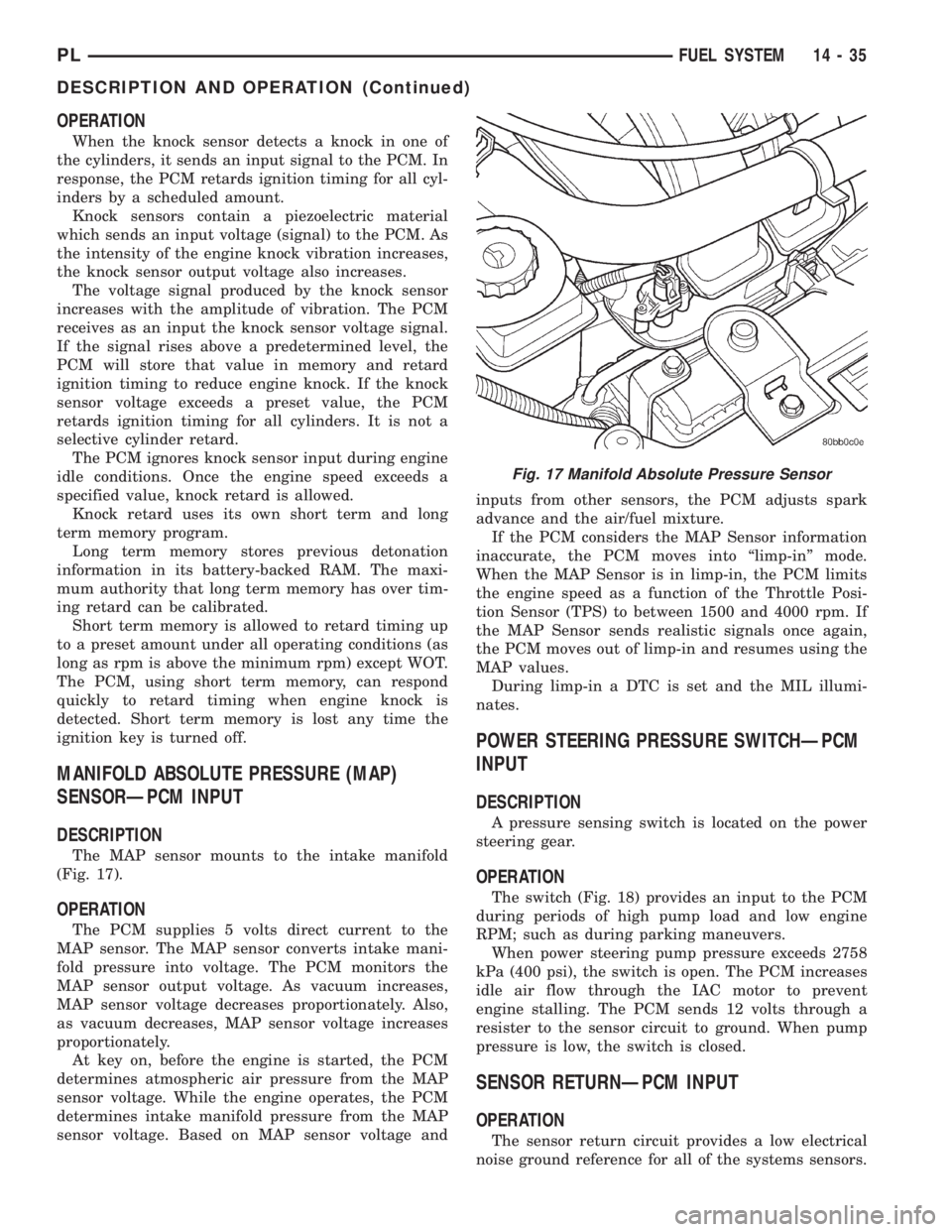
The MAP sensor mounts to the intake manifold
(Fig. 17).
OPERATION
The PCM supplies 5 volts direct current to the
MAP sensor. The MAP sensor converts intake mani-
fold pressure into voltage. The PCM monitors the
MAP sensor output voltage. As vacuum increases,
MAP sensor voltage decreases proportionately. Also,
as vacuum decreases, MAP sensor voltage increases
proportionately.
At key on, before the engine is started, the PCM
determines atmospheric air pressure from the MAP
sensor voltage. While the engine operates, the PCM
determines intake manifold pressure from the MAP
sensor voltage. Based on MAP sensor voltage andinputs from other sensors, the PCM adjusts spark
advance and the air/fuel mixture.
If the PCM considers the MAP Sensor information
inaccurate, the PCM moves into ªlimp-inº mode.
When the MAP Sensor is in limp-in, the PCM limits
the engine speed as a function of the Throttle Posi-
tion Sensor (TPS) to between 1500 and 4000 rpm. If
the MAP Sensor sends realistic signals once again,
the PCM moves out of limp-in and resumes using the
MAP values.
During limp-in a DTC is set and the MIL illumi-
nates.
POWER STEERING PRESSURE SWITCHÐPCM
INPUT
DESCRIPTION
A pressure sensing switch is located on the power
steering gear.
OPERATION
The switch (Fig. 18) provides an input to the PCM
during periods of high pump load and low engine
RPM; such as during parking maneuvers.
When power steering pump pressure exceeds 2758
kPa (400 psi), the switch is open. The PCM increases
idle air flow through the IAC motor to prevent
engine stalling. The PCM sends 12 volts through a
resister to the sensor circuit to ground. When pump
pressure is low, the switch is closed.
SENSOR RETURNÐPCM INPUT
OPERATION
The sensor return circuit provides a low electrical
noise ground reference for all of the systems sensors.
Fig. 17 Manifold Absolute Pressure Sensor
PLFUEL SYSTEM 14 - 35
DESCRIPTION AND OPERATION (Continued)