2000 DODGE NEON timing belt
[x] Cancel search: timing beltPage 5 of 1285

30,000 Miles (48 000 km) or at 24 months
²Change the engine oil.
²Replace the engine oil filter.
²Lubricate the front suspension lower ball joint.
²Inspect the tie rod ends and boot seals.
²Adjust the drive belt tension.
²Replace the engine air cleaner element (fil-
ter).
²Replace the engine spark plugs
²Change the automatic transaxle fluid.
37,500 Miles (60 000 km) or at 30 months
²Change the engine oil.
²Replace the engine oil filter.
45,000 Miles (72 000 km) or at 36 months
²Change the engine oil.
²Replace the engine oil filter.
²Inspect the front brake pads and rear brake lin-
ings.
²Adjust the drive belt tension.
²Flush and replace the engine coolant at 36
months, regardless of mileage.
52,500 Miles (84 000 km) or at 42 months
²Change the engine oil.
²Replace the engine oil filter.
²Flush and replace the engine coolant if not done
at 36 months.
60,000 Miles (96 000 km) or at 48 months
²Change the engine oil.
²Replace the engine oil filter.
²Check the PCV valve and replace, if neces-
sary. Not required if previously changed.*
²Lubricate the front suspension lower ball joints.
²Replace the drive belts.
²Replace the engine air cleaner element (fil-
ter).
²Replace the ignition cables.
²Replace the spark plugs.
²Change the automatic transaxle fluid.
67,500 Miles (108 000 km) or at 54 months
²Change the engine oil.
²Replace the engine oil filter.
²Inspect the front brake pads and rear brake lin-
ings.
75,000 Miles (120 000 km) or at 60 months
²Change the engine oil.
²Replace the engine oil filter.
²Adjust the drive belt tension.
²Flush and replace engine coolant if has been
30,000 miles (48 000 km) or 24 months since last
change.
82,500 Miles (132 000 km) or at 66 months
²Change the engine oil.
²Replace the engine oil filter.
²Flush and replace engine coolant if it has been
30,000 miles (48 000 km) or 24 months since last
change.
90,000 Miles (144 000 km) or at 72 months
²Change the engine oil.
²Replace the engine oil filter.
²Check the PCV valve and replace, if neces-
sary. Not required if previously changed.*
²Lubricate the front suspension lower ball joints.
²Inspect the front brake pads and rear brake lin-
ings.
²Adjust the drive belt tension.
²Replace the engine air cleaner element (fil-
ter).
²Replace the spark plugs.
²Inspect the serpentine drive belt, replace if nec-
essary. This maintenance is not required if the belt
was previously replaced.
²Change the automatic transaxle fluid.
97,500 Miles (156 000 km) or at 78 months
²Change the engine oil.
²Replace the engine oil filter.
105,000 Miles (168 000 km) or at 84 months
²Change the engine oil.
²Replace the engine oil filter.
²Replace the engine timing belt.
²Adjust the drive belt tension.
*This maintenance is recommended by Daimler-
Chrysler Corporation to the owner but is not
required to maintain the emissions warranty.
NOTE: Inspection and service should also be per-
formed anytime a malfunction is observed or sus-
pected. Retain all receipts.
SCHEDULE ± B
3,000 Miles (5 000 km)
²Change the engine oil.
6,000 Miles (10 000 km)
²Change the engine oil.
²Replace the engine oil filter.
9,000 Miles (14 000 km)
²Change the engine oil.
²Inspect the front brake pads and rear brake lin-
ings.
0 - 4 LUBRICATION AND MAINTENANCEPL
SPECIFICATIONS (Continued)
Page 7 of 1285

69,000 Miles (110 000 km)
²Change the engine oil.
72,000 Miles (115 000 km)
²Change the engine oil.
²Replace the engine oil filter.
²Inspect the front brake pads and rear brake lin-
ings.
75,000 Miles (120 000 km)
²Change the engine oil.
²Adjust the drive belt tension.
²Inspect theengine air cleaner element (fil-
ter)and replace as necessary.*
²Change the automatic transaxle fluid/filter and
adjust bands.
78,000 Miles (125 000 km)
²Change the engine oil.
²Replace the engine oil filter.
81,000 Miles (130 000 km)
²Change the engine oil.
²Flush and replace the engine coolant.
²Inspect the front brake pads and rear brake lin-
ings.
84,000 Miles (134 000 km)
²Change the engine oil.
²Replace the engine oil filter.
87,000 Miles (139 000 km)
²Change the engine oil.
90,000 Miles (144 000 km)
²Change the engine oil.
²Replace the engine oil filter.
²Inspect front brake pads and rear brake linings
²Check thePCV valveand replace if necessary.
Not required if previously changed.*
²Lubricate the front suspension lower ball joint.
²Replace theengine air cleaner element (fil-
ter).²Replace thespark plugs
²Change the automatic transaxle fluid/filter and
adjust the bands.
93,000 Miles (149 000 km)
²Change the engine oil.
96,000 Miles (154 000 km)
²Change the engine oil.
²Replace the engine oil filter.
99,000 Miles (158 000 km)
²Change the engine oil.
²Inspect the front brake pads and rear brake lin-
ings.
102,000 Miles (163 000 km)
²Change the engine oil.
²Replace the engine oil filter.
105,000 Miles (168 000 km)
²Replace theengine timing belt.
²Change the engine oil.
²Adjust the drive belt tension.
²Inspect theengine air cleaner element (fil-
ter)and replace as necessary.*
²Change the automatic transaxle fluid/filter and
adjust the bands.
²Flush and replace the engine coolant.
* This maintenance is recommended by Daimler-
Chrysler Corporation to the owner but is not
required to maintain the emissions warranty.
NOTE: Operating the vehicle more than 50% in
heavy traffic during hot weather, above 90É F (32É
C), using vehicle for police, taxi, limousine type
operation or trailer towing require the more fre-
quent transaxle service noted in Schedule ± B. Per-
form these services if vehicle usually operate under
these conditions.
Inspection and service should also be performed
anytime a malfunction is observed or suspected.
0 - 6 LUBRICATION AND MAINTENANCEPL
SPECIFICATIONS (Continued)
Page 184 of 1285

RADIATOR HOSES AND CLAMPS
WARNING: IF VEHICLE HAS BEEN RUN RECENTLY,
WAIT 15 MINUTES BEFORE WORKING ON VEHI-
CLE. RELIEVE PRESSURE BY PLACING A SHOP
TOWEL OVER THE CAP AND WITHOUT PUSHING
DOWN ROTATE IT COUNTERCLOCKWISE TO THE
FIRST STOP. ALLOW FLUIDS TO ESCAPE
THROUGH THE OVERFLOW TUBE AND WHEN THE
SYSTEM STOPS PUSHING OUT COOLANT AND
STEAM AND THE PRESSURE DROPS CONTINUE
SERVICE.
WARNING: CONSTANT TENSION HOSE CLAMPS
ARE USED ON MOST COOLING SYSTEM HOSES.
WHEN REMOVING OR INSTALLING, USE ONLY
TOOLS DESIGNED FOR SERVICING THIS TYPE OF
CLAMP. ALWAYS WEAR SAFETY GLASSES WHEN
SERVICING CONSTANT TENSION CLAMPS.
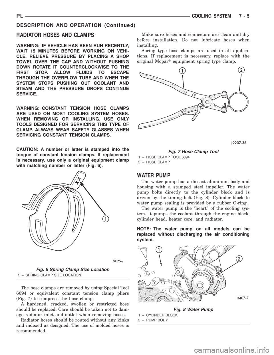
CAUTION: A number or letter is stamped into the
tongue of constant tension clamps. If replacement
is necessary, use only a original equipment clamp
with matching number or letter (Fig. 6).
The hose clamps are removed by using Special Tool
6094 or equivalent constant tension clamp pliers
(Fig. 7) to compress the hose clamp.
A hardened, cracked, swollen or restricted hose
should be replaced. Care should be taken not to dam-
age radiator inlet and outlet when removing hoses.
Radiator hoses should be routed without any kinks
and indexed as designed. The use of molded hoses is
recommended.Make sure hoses and connectors are clean and dry
before installation. Do not lubricate hoses when
installing.
Spring type hose clamps are used in all applica-
tions. If replacement is necessary, replace with the
original Mopartequipment spring type clamp.
WATER PUMP
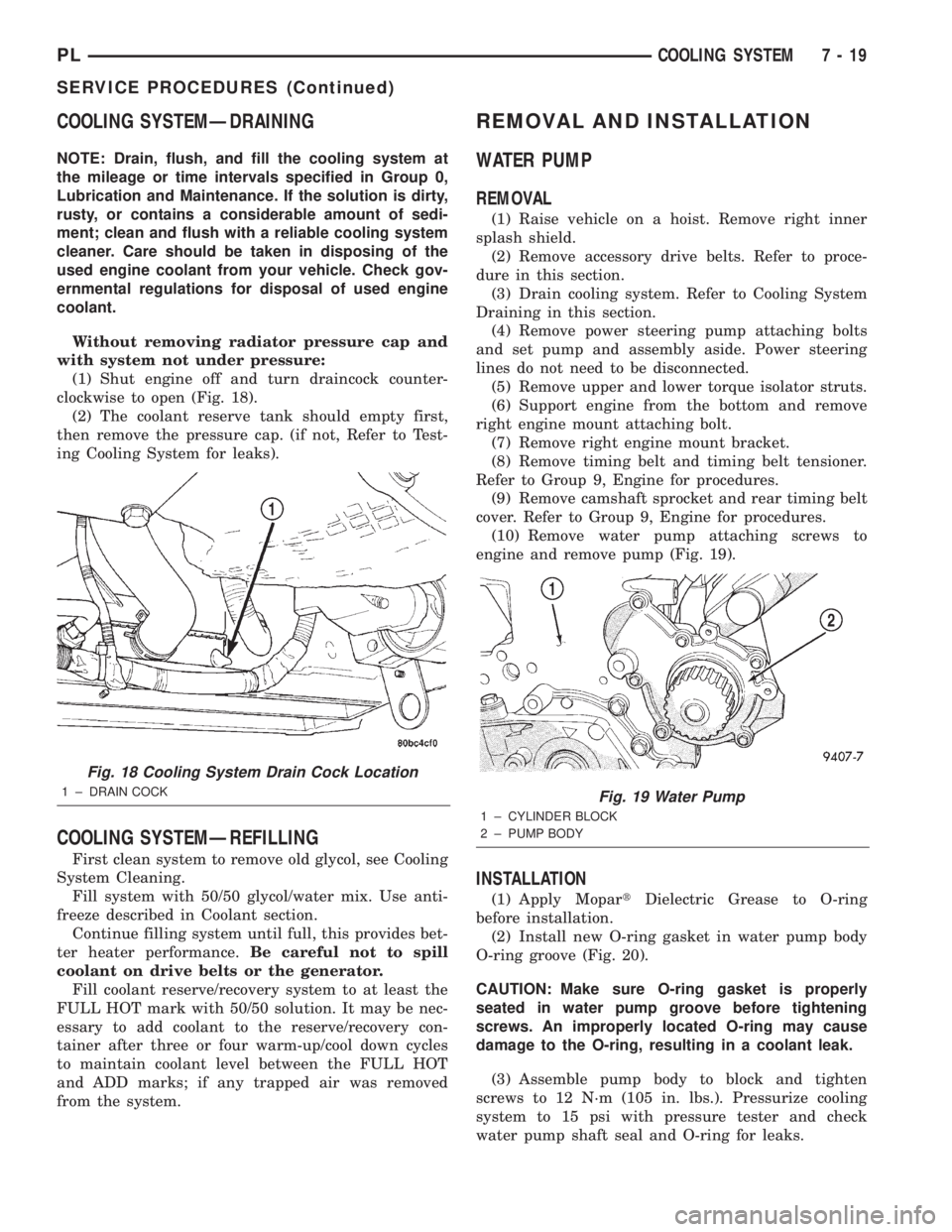
The water pump has a diecast aluminum body and
housing with a stamped steel impeller. The water
pump bolts directly to the cylinder block and is
driven by the timing belt (Fig. 8). Cylinder block to
water pump sealing is provided by a rubber O-ring.
The water pump is the ªheartº of the cooling sys-
tem. It pumps the coolant through the engine block,
cylinder head, heater core, and radiator.
NOTE: The water pump on all models can be
replaced without discharging the air conditioning
system.
Fig. 6 Spring Clamp Size Location
1 ± SPRING CLAMP SIZE LOCATION
Fig. 7 Hose Clamp Tool
1 ± HOSE CLAMP TOOL 6094
2 ± HOSE CLAMP
Fig. 8 Water Pump
1 ± CYLINDER BLOCK
2 ± PUMP BODY
PLCOOLING SYSTEM 7 - 5
DESCRIPTION AND OPERATION (Continued)
Page 198 of 1285

COOLING SYSTEMÐDRAINING
NOTE: Drain, flush, and fill the cooling system at
the mileage or time intervals specified in Group 0,
Lubrication and Maintenance. If the solution is dirty,
rusty, or contains a considerable amount of sedi-
ment; clean and flush with a reliable cooling system
cleaner. Care should be taken in disposing of the
used engine coolant from your vehicle. Check gov-
ernmental regulations for disposal of used engine
coolant.
Without removing radiator pressure cap and
with system not under pressure:
(1) Shut engine off and turn draincock counter-
clockwise to open (Fig. 18).
(2) The coolant reserve tank should empty first,
then remove the pressure cap. (if not, Refer to Test-
ing Cooling System for leaks).
COOLING SYSTEMÐREFILLING
First clean system to remove old glycol, see Cooling
System Cleaning.
Fill system with 50/50 glycol/water mix. Use anti-
freeze described in Coolant section.
Continue filling system until full, this provides bet-
ter heater performance.Be careful not to spill
coolant on drive belts or the generator.
Fill coolant reserve/recovery system to at least the
FULL HOT mark with 50/50 solution. It may be nec-
essary to add coolant to the reserve/recovery con-
tainer after three or four warm-up/cool down cycles
to maintain coolant level between the FULL HOT
and ADD marks; if any trapped air was removed
from the system.
REMOVAL AND INSTALLATION
WATER PUMP
REMOVAL
(1) Raise vehicle on a hoist. Remove right inner
splash shield.
(2) Remove accessory drive belts. Refer to proce-
dure in this section.
(3) Drain cooling system. Refer to Cooling System
Draining in this section.
(4) Remove power steering pump attaching bolts
and set pump and assembly aside. Power steering
lines do not need to be disconnected.
(5) Remove upper and lower torque isolator struts.
(6) Support engine from the bottom and remove
right engine mount attaching bolt.
(7) Remove right engine mount bracket.
(8) Remove timing belt and timing belt tensioner.
Refer to Group 9, Engine for procedures.
(9) Remove camshaft sprocket and rear timing belt
cover. Refer to Group 9, Engine for procedures.
(10) Remove water pump attaching screws to
engine and remove pump (Fig. 19).
INSTALLATION
(1) Apply MopartDielectric Grease to O-ring
before installation.
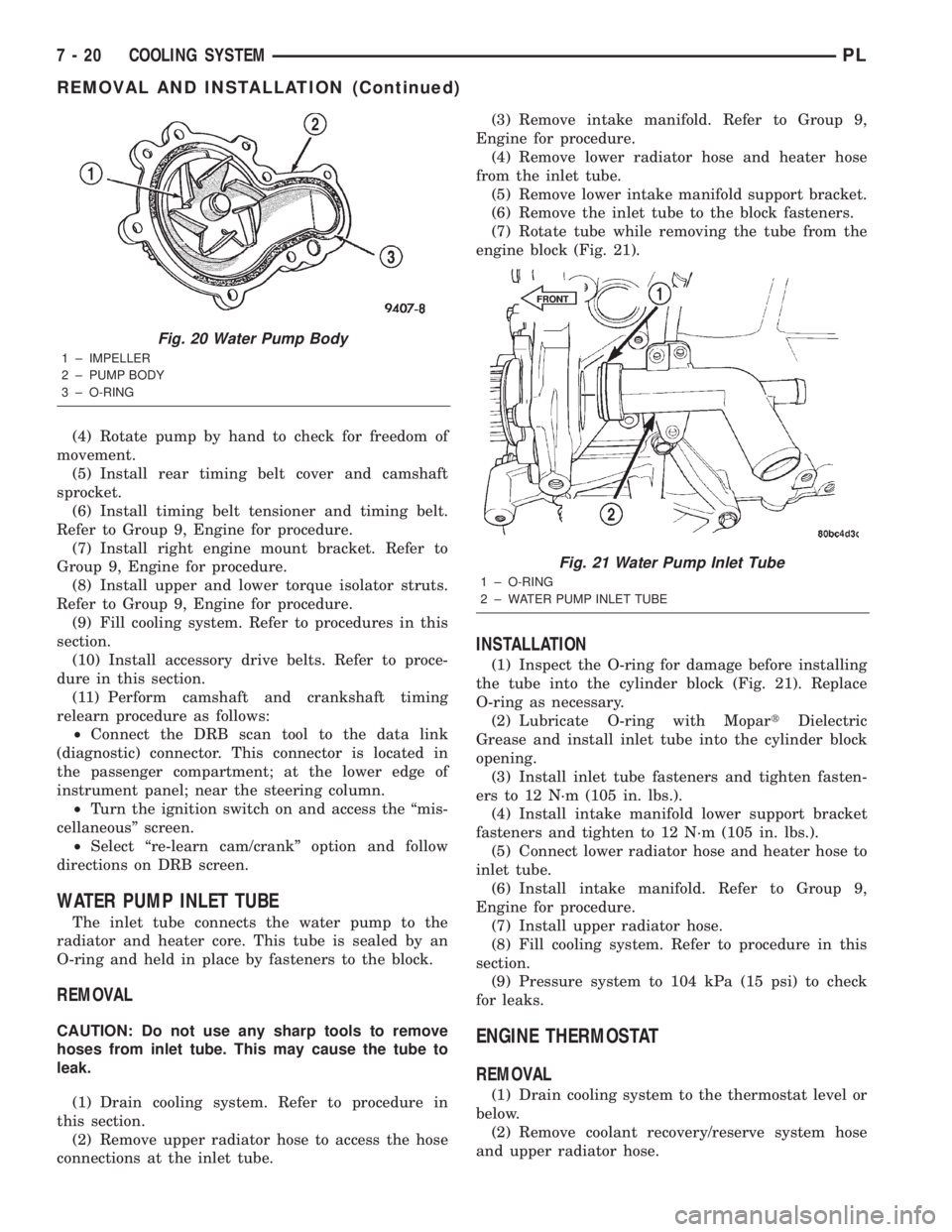
(2) Install new O-ring gasket in water pump body
O-ring groove (Fig. 20).
CAUTION: Make sure O-ring gasket is properly
seated in water pump groove before tightening
screws. An improperly located O-ring may cause
damage to the O-ring, resulting in a coolant leak.
(3) Assemble pump body to block and tighten
screws to 12 N´m (105 in. lbs.). Pressurize cooling
system to 15 psi with pressure tester and check
water pump shaft seal and O-ring for leaks.
Fig. 18 Cooling System Drain Cock Location
1 ± DRAIN COCKFig. 19 Water Pump
1 ± CYLINDER BLOCK
2 ± PUMP BODY
PLCOOLING SYSTEM 7 - 19
SERVICE PROCEDURES (Continued)
Page 199 of 1285

(4) Rotate pump by hand to check for freedom of
movement.
(5) Install rear timing belt cover and camshaft
sprocket.
(6) Install timing belt tensioner and timing belt.
Refer to Group 9, Engine for procedure.
(7) Install right engine mount bracket. Refer to
Group 9, Engine for procedure.
(8) Install upper and lower torque isolator struts.
Refer to Group 9, Engine for procedure.
(9) Fill cooling system. Refer to procedures in this
section.
(10) Install accessory drive belts. Refer to proce-
dure in this section.
(11) Perform camshaft and crankshaft timing
relearn procedure as follows:
²Connect the DRB scan tool to the data link
(diagnostic) connector. This connector is located in
the passenger compartment; at the lower edge of
instrument panel; near the steering column.
²Turn the ignition switch on and access the ªmis-
cellaneousº screen.
²Select ªre-learn cam/crankº option and follow
directions on DRB screen.
WATER PUMP INLET TUBE
The inlet tube connects the water pump to the
radiator and heater core. This tube is sealed by an
O-ring and held in place by fasteners to the block.
REMOVAL
CAUTION: Do not use any sharp tools to remove
hoses from inlet tube. This may cause the tube to
leak.
(1) Drain cooling system. Refer to procedure in
this section.
(2) Remove upper radiator hose to access the hose
connections at the inlet tube.(3) Remove intake manifold. Refer to Group 9,
Engine for procedure.
(4) Remove lower radiator hose and heater hose
from the inlet tube.
(5) Remove lower intake manifold support bracket.
(6) Remove the inlet tube to the block fasteners.
(7) Rotate tube while removing the tube from the
engine block (Fig. 21).
INSTALLATION
(1) Inspect the O-ring for damage before installing
the tube into the cylinder block (Fig. 21). Replace
O-ring as necessary.
(2) Lubricate O-ring with MopartDielectric
Grease and install inlet tube into the cylinder block
opening.
(3) Install inlet tube fasteners and tighten fasten-
ers to 12 N´m (105 in. lbs.).
(4) Install intake manifold lower support bracket
fasteners and tighten to 12 N´m (105 in. lbs.).
(5) Connect lower radiator hose and heater hose to
inlet tube.
(6) Install intake manifold. Refer to Group 9,
Engine for procedure.
(7) Install upper radiator hose.
(8) Fill cooling system. Refer to procedure in this
section.
(9) Pressure system to 104 kPa (15 psi) to check
for leaks.
ENGINE THERMOSTAT
REMOVAL
(1) Drain cooling system to the thermostat level or
below.
(2) Remove coolant recovery/reserve system hose
and upper radiator hose.
Fig. 20 Water Pump Body
1 ± IMPELLER
2 ± PUMP BODY
3 ± O-RING
Fig. 21 Water Pump Inlet Tube
1 ± O-RING
2 ± WATER PUMP INLET TUBE
FRONT
7 - 20 COOLING SYSTEMPL
REMOVAL AND INSTALLATION (Continued)
Page 238 of 1285

OPERATION
The Automatic Shutdown (ASD) relay supplies bat-
tery voltage to the fuel injectors, electronic ignition
coil and the heating elements in the oxygen sensors.
A buss bar in the Power Distribution Center (PDC)
supplies voltage to the solenoid side and contact side
of the relay. The fuse also protects the power circuit
for the fuel pump relay and pump. The fuse is
located in the PDC. Refer to the Wiring Diagrams for
circuit information.
The PCM controls the ASD relay by switching the
ground path for the solenoid side of the relay on and
off. The PCM turns the ground path off when the
ignition switch is in the Off position. When the igni-
tion switch is in On or Start, the PCM monitors the
crankshaft and camshaft position sensor signals to
determine engine speed and ignition timing (coil
dwell). If the PCM does not receive crankshaft and
camshaft position sensor signals when the ignition
switch is in the Run position, it will de-energize the
ASD relay.
CRANKSHAFT POSITION SENSORÐPCM
INPUT
DESCRIPTION
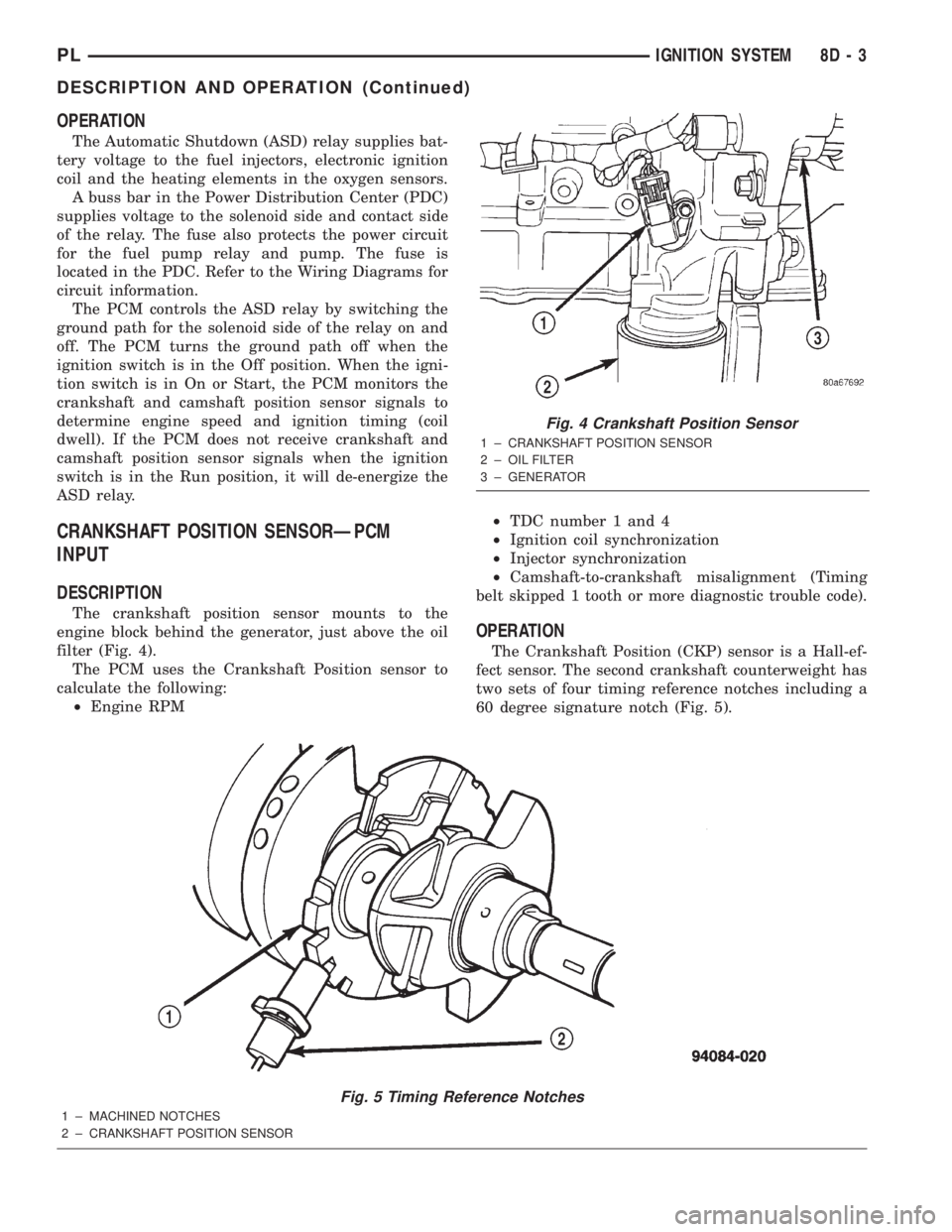
The crankshaft position sensor mounts to the
engine block behind the generator, just above the oil
filter (Fig. 4).
The PCM uses the Crankshaft Position sensor to
calculate the following:
²Engine RPM²TDC number 1 and 4
²Ignition coil synchronization
²Injector synchronization
²Camshaft-to-crankshaft misalignment (Timing
belt skipped 1 tooth or more diagnostic trouble code).
OPERATION
The Crankshaft Position (CKP) sensor is a Hall-ef-
fect sensor. The second crankshaft counterweight has
two sets of four timing reference notches including a
60 degree signature notch (Fig. 5).
Fig. 5 Timing Reference Notches
1 ± MACHINED NOTCHES
2 ± CRANKSHAFT POSITION SENSOR
Fig. 4 Crankshaft Position Sensor
1 ± CRANKSHAFT POSITION SENSOR
2 ± OIL FILTER
3 ± GENERATOR
PLIGNITION SYSTEM 8D - 3
DESCRIPTION AND OPERATION (Continued)
Page 726 of 1285

CAUTION: Do not drive cup plug into the casting
as restricted cooling can result and cause serious
engine problems.
INSTALLATION
Thoroughly clean all debris/rust from inside of cup
plug hole in cylinder block or head. Be sure to
remove old sealer. Lightly coat inside of cup plug hole
with MopartStud and Bearing Mount Adhesive.
Make certain the new plug is cleaned of all oil or
grease. Using a proper driver, drive plug into hole so
that the sharp edge of the plug is at least 0.5 mm
(0.020 inch.) inside the lead in chamfer (Fig. 3).
It is not necessary to wait for curing of the sealant.
The cooling system can be refilled and the vehicle
placed in service immediately.
ENGINE PERFORMANCE
If a loss of performance is noticed, timing belt or
chain may have skipped one or two teeth. Camshaft
and crankshaft timing should be checked. Refer to
Group 9, Engine Timing belt or chain installation.
It is important that the vehicle is operating to it's
optimum performance level to maintain fuel economy
and lowest vehicle emissions. If vehicle is not operat-ing to these standards, refer to Engine Diagnosis in
this section. The following procedures can assist in
achieving the proper engine diagnosis.
(1) Test cranking amperage draw. Refer to Group
8B, Starting.
(2) Check intake manifold for vacuum leaks.
(3) Perform cylinder compression pressure test.
Refer to Engine Diagnosis in this section.
(4) Clean or replace spark plugs as necessary and
adjust gap as specified in Group 8D, Ignition System.
Tighten to specifications.
(5) Test resistance of spark plug cables. Refer to
Group 8D, Ignition System.
(6) Test ignition coils primary and secondary resis-
tance. Replace parts as necessary. Refer to Group 8D,
Ignition System.
(7) Check fuel pump pressure at idle and different
RPM ranges. Refer to Group 14, Fuel System for
specifications.
(8) The air filter elements should be replaced as
specified in Group 0, Lubrication and Maintenance.
(9) Inspect crankcase ventilation system. Refer to
Group 25, Emission Control Systems.
(10) Road test vehicle as a final test.HONING CYLINDER BORES
(1) Used carefully, the cylinder bore resizing hone,
recommended tool C-823 or equivalent, equipped
with 220 grit stones, is the best tool for this honing
procedure. In addition to deglazing, it will reduce
taper and out-of-round as well as removing light
scuffing, scoring or scratches. Usually a few strokes
Fig. 2 Access Plug
1 ± CRANKSHAFT BOLT ACCESS PLUG
2 ± RIGHT MOUNT BOLT ACCESS PLUG
3 ± FASCIA
4 ± SPLASH SHIELD
Fig. 3 Core Hole Plug Removal
1 ± CYLINDER BLOCK
2 ± REMOVE PLUG WITH PLIERS
3 ± STRIKE HERE WITH HAMMER
4 ± DRIFT PUNCH
5 ± CUP PLUG
PLENGINE 9 - 3
GENERAL INFORMATION (Continued)
Page 734 of 1285

ENGINE DIAGNOSISÐPERFORMANCE
CONDITION POSSIBLE CAUSE CORRECTION
ENGINE WILL NOT START 1. Weak battery. 1. Test battery. Charge or replace
as necessary. Refer to Group 8A,
Battery.
2. Corroded or loose battery
connections.2. Clean and tighten battery
connections. Apply a coat of light
mineral grease to terminals.
3. Faulty starter. 3. Test starting system. Refer to
Group 8B, Starting.
4. Faulty coil(s) or control unit. 4. Test and replace as needed.
Refer to Group 8D, Ignition System.
5. Incorrect spark plug gap. 5. Set gap. Refer to Group 8D,
Ignition System.
6. Contamination in fuel system. 6. Clean system and replace fuel
filter.
7. Faulty fuel pump. 7. Test fuel pump and replace as
needed. Refer to Group 14, Fuel
System.
8. Incorrect engine timing. 8. Check for a skipped timing
belt/chain.
ENGINE STALLS OR IDLES
ROUGH1. Idle speed too low. 1. Test minimum air flow. Refer to
Group 14, Fuel System.
2. Incorrect fuel mixture. 2. Refer to Group 14, Fuel System.
3. Intake manifold leakage. 3. Inspect intake manifold, manifold
gasket, and vacuum hoses.
4. Faulty coil(s). 4. Test and replace as necessary.
Refer to Group 8D, Ignition System.
ENGINE LOSS OF POWER 1. Dirty or incorrectly gapped plugs. 1. Clean plugs and set gap. Refer to
Group 8D, Ignition System.
2. Contamination in fuel system. 2. Clean system and replace fuel
filter.
3. Faulty fuel pump. 3. Test and replace as necessary.
Refer to Group 14, Fuel System.
4. Incorrect valve timing. 4. Correct valve timing.
5. Leaking cylinder head gasket. 5. Replace cylinder head gasket.
6. Low compression. 6. Test compression of each
cylinder.
7. Burned, warped, or pitted valves. 7. Replace valves.
8. Plugged or restricted exhaust
system.8. Install new parts, as necessary.
9. Faulty coil(s). 9. Test and replace as necessary.
Refer to Group 8D, Ignition System.
PLENGINE 9 - 11
DIAGNOSIS AND TESTING (Continued)