2000 DODGE NEON compression ratio
[x] Cancel search: compression ratioPage 237 of 1285

Loose cable connections will corrode, increase resis-
tance and permit water to enter the coil towers.
These conditions can cause ignition malfunction.
Plastic clips in various locations protect the cables
from damage. When the cables are replaced the clips
must be used to prevent damage to the cables, and
should be rotated about 30É below the horizontal.
ELECTRONIC IGNITION COILS
DESCRIPTION
The coil pack consists of 2 coils molded together.
The coil pack is mounted on the valve cover (Fig. 2).
OPERATION
WARNING: THE DIRECT IGNITION SYSTEM GEN-
ERATES APPROXIMATELY 40,000 VOLTS. PER-
SONAL INJURY COULD RESULT FROM CONTACT
WITH THIS SYSTEM.
High tension leads route to each cylinder from the
coil. The coil fires two spark plugs every power
stroke. One plug is the cylinder under compression,
the other cylinder fires on the exhaust stroke. Coil
number one fires cylinders 1 and 4. Coil number two
fires cylinders 2 and 3. The PCM determines which
of the coils to charge and fire at the correct time.
The Auto Shutdown (ASD) relay provides battery
voltage to the ignition coil. The PCM provides a
ground contact (circuit) for energizing the coil. When
the PCM breaks the contact, the energy in the coil
primary transfers to the secondary causing thespark. The PCM will de-energize the ASD relay if it
does not receive the crankshaft position sensor and
camshaft position sensor inputs. Refer to Auto Shut-
down (ASD) RelayÐPCM Output, in this section for
relay operation.
AUTOMATIC SHUTDOWN RELAY
DESCRIPTION
The ASD relay is located in the PDC (Fig. 3). The
inside top of the PDC cover has label showing relay
and fuse identification.
Fig. 1 Checking Spark Plug Electrode Gap
1 ± TAPER GAUGE
Fig. 2 Ignition Coil Pack
1 ± IGNITION COILS
2 ± SPARK PLUG CABLE
3 ± SPARK PLUG INSULATOR
Fig. 3 Power Distribution Center (PDC)
8D - 2 IGNITION SYSTEMPL
DESCRIPTION AND OPERATION (Continued)
Page 739 of 1285
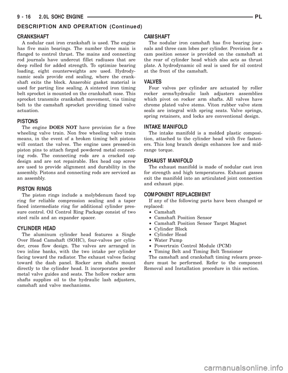
CRANKSHAFT
A nodular cast iron crankshaft is used. The engine
has five main bearings. The number three main is
flanged to control thrust. The mains and connecting
rod journals have undercut fillet radiuses that are
deep rolled for added strength. To optimize bearing
loading, eight counterweights are used. Hydrody-
namic seals provide end sealing, where the crank-
shaft exits the block. Anaerobic gasket material is
used for parting line sealing. A sintered iron timing
belt sprocket is mounted on the crankshaft nose. This
sprocket transmits crankshaft movement, via timing
belt to the camshaft sprocket providing timed valve
actuation.
PISTONS
The engineDOES NOThave provision for a free
wheeling valve train. Non free wheeling valve train
means, in the event of a broken timing belt pistons
will contact the valves. The engine uses pressed-in
piston pins to attach forged powdered metal connect-
ing rods. The connecting rods are a cracked cap
design and are not repairable. Hex head cap screw
are used to provide alignment and durability in the
assembly. Pistons and connecting rods are serviced as
an assembly.
PISTON RINGS
The piston rings include a molybdenum faced top
ring for reliable compression sealing and a taper
faced intermediate ring for additional cylinder pres-
sure control. Oil Control Ring Package consist of two
steel rails and an expander spacer.
CYLINDER HEAD
The aluminum cylinder head features a Single
Over Head Camshaft (SOHC), four-valves per cylin-
der, cross flow design. The valves are arranged in
two inline banks, with the two intake per cylinder
facing toward the radiator. The exhaust valves facing
toward the dash panel. Rocker arm shafts mount
directly to the cylinder head. It incorporates powder
metal valve guides and seats. The hollow rocker arm
shafts supplies oil to the hydraulic lash adjusters,
camshaft and valve mechanisms.
CAMSHAFT
The nodular iron camshaft has five bearing jour-
nals and three cam lobes per cylinder. Provision for a
cam position sensor is provided on the camshaft at
the rear of cylinder head which also acts as thrust
plate. A hydrodynamic oil seal is used for oil control
at the front of the camshaft.
VALVES
Four valves per cylinder are actuated by roller
rocker arms/hydraulic lash adjusters assemblies
which pivot on rocker arm shafts. All valves have
chrome plated valve stems. Viton rubber valve stem
seals are integral with spring seats. Valve springs,
spring retainers, and locks are conventional design.
INTAKE MANIFOLD
The intake manifold is a molded plastic composi-
tion, attached to the cylinder head with five fasten-
ers. This long branch design enhances low and mid-
range torque.
EXHAUST MANIFOLD
The exhaust manifold is made of nodular cast iron
for strength and high temperatures. Exhaust gasses
exit the manifold into an articulated joint connection
and exhaust pipe.
COMPONENT REPLACEMENT
If any of the following parts have been changed or
replaced:
²Camshaft
²Camshaft Position Sensor
²Camshaft Position Sensor Target Magnet
²Cylinder Block
²Cylinder Head
²Water Pump
²Powertrain Control Module (PCM)
²Timing Belt and Timing Belt Tensioner
The camshaft and crankshaft timing relearn proce-
dure must be performed. Refer to the component
Removal and Installation procedure in this section.
9 - 16 2.0L SOHC ENGINEPL
DESCRIPTION AND OPERATION (Continued)
Page 782 of 1285
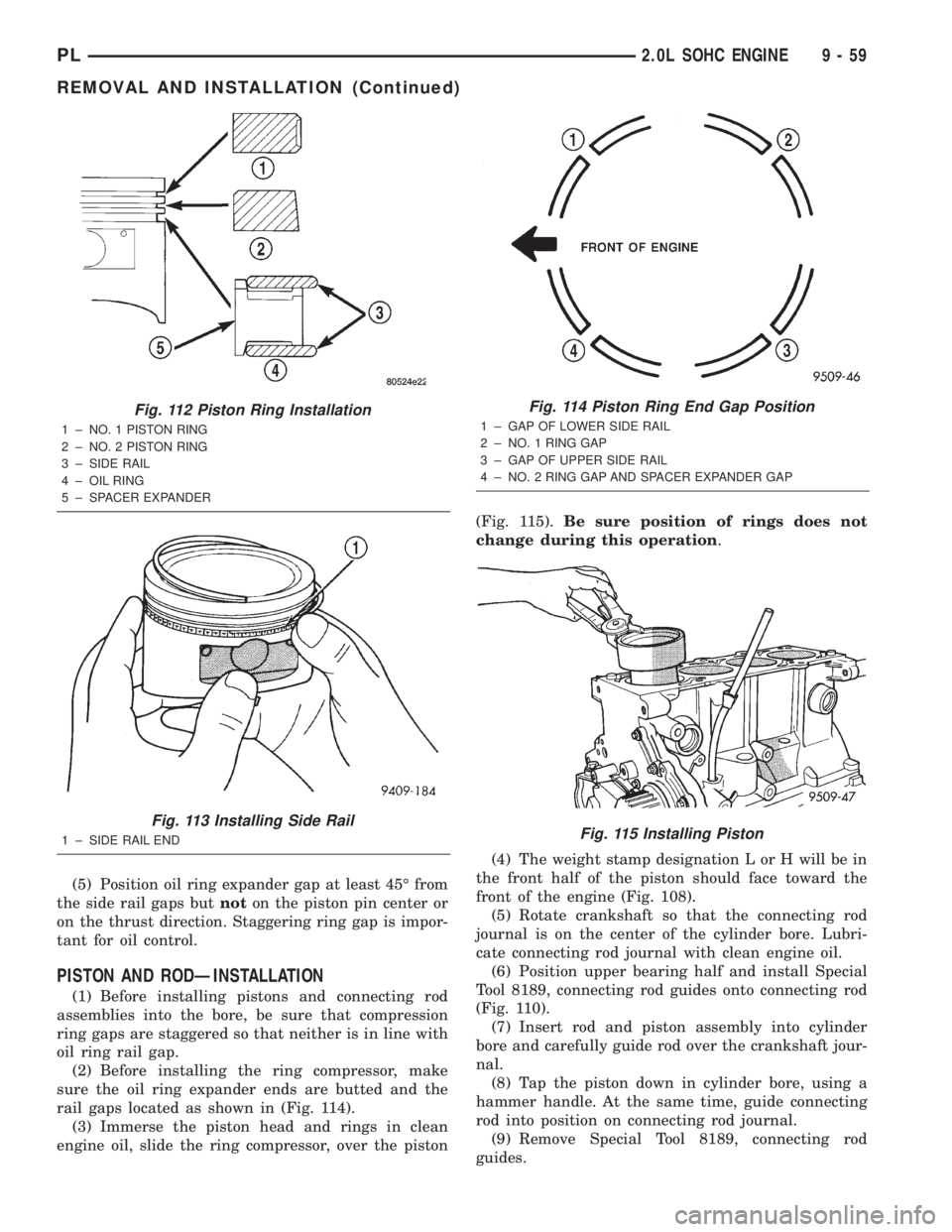
(5) Position oil ring expander gap at least 45É from
the side rail gaps butnoton the piston pin center or
on the thrust direction. Staggering ring gap is impor-
tant for oil control.
PISTON AND RODÐINSTALLATION
(1) Before installing pistons and connecting rod
assemblies into the bore, be sure that compression
ring gaps are staggered so that neither is in line with
oil ring rail gap.
(2) Before installing the ring compressor, make
sure the oil ring expander ends are butted and the
rail gaps located as shown in (Fig. 114).
(3) Immerse the piston head and rings in clean
engine oil, slide the ring compressor, over the piston(Fig. 115).Be sure position of rings does not
change during this operation.
(4) The weight stamp designation L or H will be in
the front half of the piston should face toward the
front of the engine (Fig. 108).
(5) Rotate crankshaft so that the connecting rod
journal is on the center of the cylinder bore. Lubri-
cate connecting rod journal with clean engine oil.
(6) Position upper bearing half and install Special
Tool 8189, connecting rod guides onto connecting rod
(Fig. 110).
(7) Insert rod and piston assembly into cylinder
bore and carefully guide rod over the crankshaft jour-
nal.
(8) Tap the piston down in cylinder bore, using a
hammer handle. At the same time, guide connecting
rod into position on connecting rod journal.
(9) Remove Special Tool 8189, connecting rod
guides.
Fig. 112 Piston Ring Installation
1 ± NO. 1 PISTON RING
2 ± NO. 2 PISTON RING
3 ± SIDE RAIL
4 ± OIL RING
5 ± SPACER EXPANDER
Fig. 113 Installing Side Rail
1 ± SIDE RAIL END
Fig. 114 Piston Ring End Gap Position
1 ± GAP OF LOWER SIDE RAIL
2 ± NO. 1 RING GAP
3 ± GAP OF UPPER SIDE RAIL
4 ± NO. 2 RING GAP AND SPACER EXPANDER GAP
Fig. 115 Installing Piston
PL2.0L SOHC ENGINE 9 - 59
REMOVAL AND INSTALLATION (Continued)
Page 791 of 1285
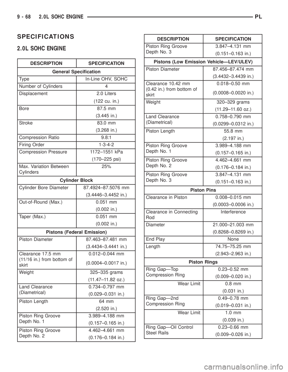
SPECIFICATIONS
2.0L SOHC ENGINE
DESCRIPTION SPECIFICATION
General Specification
Type In-Line OHV, SOHC
Number of Cylinders 4
Displacement 2.0 Liters
(122 cu. in.)
Bore 87.5 mm
(3.445 in.)
Stroke 83.0 mm
(3.268 in.)
Compression Ratio 9.8:1
Firing Order 1-3-4-2
Compression Pressure 1172±1551 kPa
(170±225 psi)
Max. Variation Between
Cylinders25%
Cylinder Block
Cylinder Bore Diameter 87.4924±87.5076 mm
(3.4446±3.4452 in.)
Out-of-Round (Max.) 0.051 mm
(0.002 in.)
Taper (Max.) 0.051 mm
(0.002 in.)
Pistons (Federal Emission)
Piston Diameter 87.463±87.481 mm
(3.4434±3.4441 in.)
Clearance 17.5 mm
(11/16 in.) from bottom of
skirt0.012±0.044 mm
(0.0004±0.0017 in.)
Weight 325±335 grams
(11.47±11.82 oz.)
Land Clearance
(Diametrical)0.734±0.797 mm
(0.029±0.031 in.)
Piston Length 64 mm
(2.520 in.)
Piston Ring Groove
Depth No. 13.989±4.188 mm
(0.157±0.165 in.)
Piston Ring Groove
Depth No. 24.462±4.661 mm
(0.176±0.184 in.)
DESCRIPTION SPECIFICATION
Piston Ring Groove
Depth No. 33.847±4.131 mm
(0.151±0.163 in.)
Pistons (Low Emission VehicleÐLEV/ULEV)
Piston Diameter 87.456±87.474 mm
(3.4432±3.4439 in.)
Clearance 10.42 mm
(0.42 in.) from bottom of
skirt0.018±0.50 mm
(0.0008±0.0020 in.)
Weight 320±329 grams
(11.29±11.60 oz.)
Land Clearance
(Diametrical)0.758±0.790 mm
(0.0299±0.0312 in.)
Piston Length 55.8 mm
(2.197 in.)
Piston Ring Groove
Depth No. 13.989±4.188 mm
(0.157±0.165 in.)
Piston Ring Groove
Depth No. 24.462±4.661 mm
(0.176±0.184 in.)
Piston Ring Groove
Depth No. 33.847±4.131 mm
(0.151±0.163 in.)
Piston Pins
Clearance in Piston 0.008±0.015 mm
(0.0003±0.0006 in.)
Clearance in Connecting
RodInterference
Diameter 21.000±21.003 mm
(0.8268±0.8269 in.)
End Play None
Length 74.75±75.25 mm
(2.943±2.963 in.)
Piston Rings
Ring GapÐTop
Compression Ring0.23±0.52 mm
(0.009±0.020 in.)
Wear Limit 0.8 mm
(0.031 in.)
Ring GapÐ2nd
Compression Ring0.49±0.78 mm
(0.019±0.031 in.)
Wear Limit 1.0 mm
(0.039 in.)
Ring GapÐOil Control
Steel Rails0.23±0.66 mm
(0.009±0.026 in.)
9 - 68 2.0L SOHC ENGINEPL
Page 792 of 1285
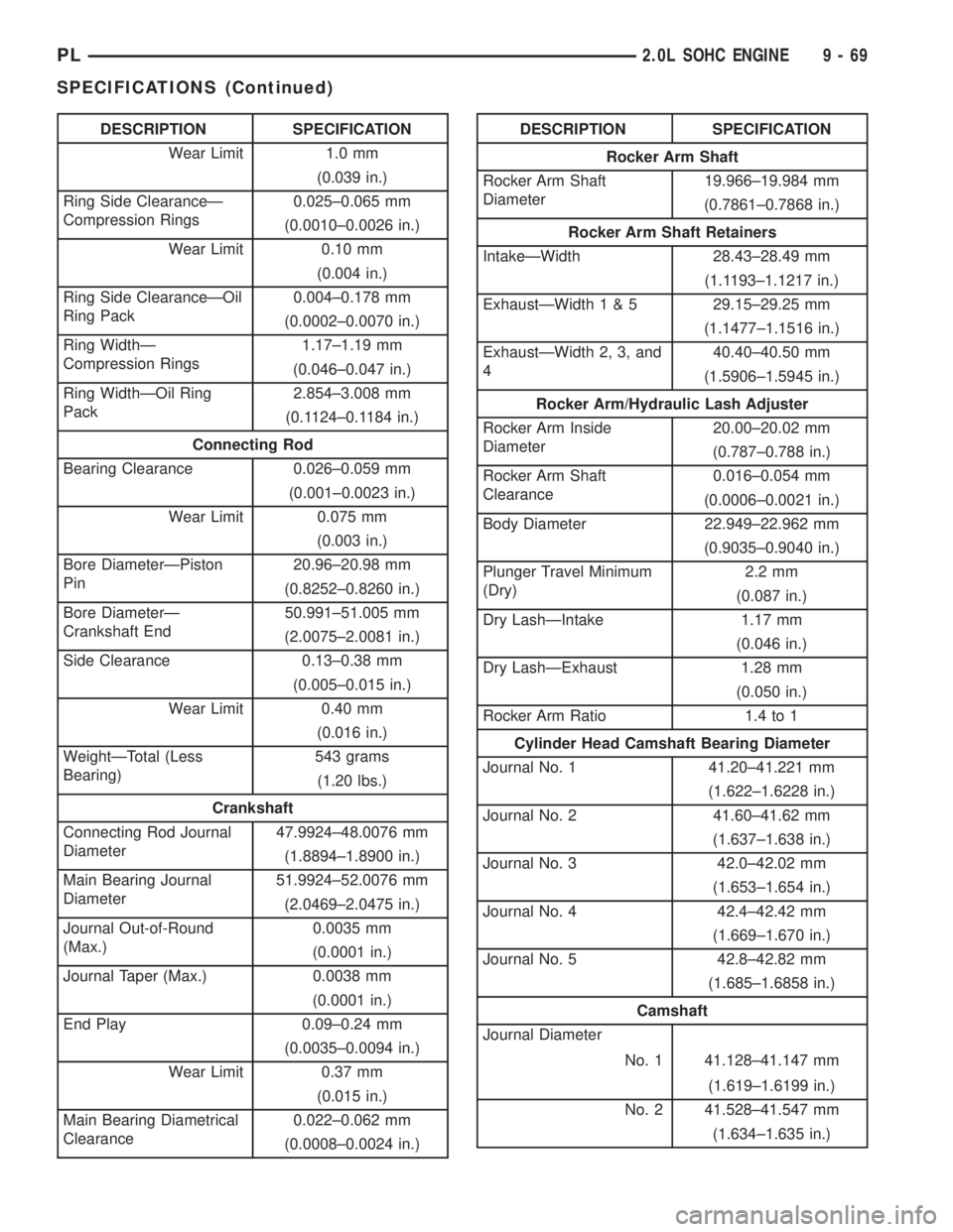
DESCRIPTION SPECIFICATION
Wear Limit 1.0 mm
(0.039 in.)
Ring Side ClearanceÐ
Compression Rings0.025±0.065 mm
(0.0010±0.0026 in.)
Wear Limit 0.10 mm
(0.004 in.)
Ring Side ClearanceÐOil
Ring Pack0.004±0.178 mm
(0.0002±0.0070 in.)
Ring WidthÐ
Compression Rings1.17±1.19 mm
(0.046±0.047 in.)
Ring WidthÐOil Ring
Pack2.854±3.008 mm
(0.1124±0.1184 in.)
Connecting Rod
Bearing Clearance 0.026±0.059 mm
(0.001±0.0023 in.)
Wear Limit 0.075 mm
(0.003 in.)
Bore DiameterÐPiston
Pin20.96±20.98 mm
(0.8252±0.8260 in.)
Bore DiameterÐ
Crankshaft End50.991±51.005 mm
(2.0075±2.0081 in.)
Side Clearance 0.13±0.38 mm
(0.005±0.015 in.)
Wear Limit 0.40 mm
(0.016 in.)
WeightÐTotal (Less
Bearing)543 grams
(1.20 lbs.)
Crankshaft
Connecting Rod Journal
Diameter47.9924±48.0076 mm
(1.8894±1.8900 in.)
Main Bearing Journal
Diameter51.9924±52.0076 mm
(2.0469±2.0475 in.)
Journal Out-of-Round
(Max.)0.0035 mm
(0.0001 in.)
Journal Taper (Max.) 0.0038 mm
(0.0001 in.)
End Play 0.09±0.24 mm
(0.0035±0.0094 in.)
Wear Limit 0.37 mm
(0.015 in.)
Main Bearing Diametrical
Clearance0.022±0.062 mm
(0.0008±0.0024 in.)DESCRIPTION SPECIFICATION
Rocker Arm Shaft
Rocker Arm Shaft
Diameter19.966±19.984 mm
(0.7861±0.7868 in.)
Rocker Arm Shaft Retainers
IntakeÐWidth 28.43±28.49 mm
(1.1193±1.1217 in.)
ExhaustÐWidth1&529.15±29.25 mm
(1.1477±1.1516 in.)
ExhaustÐWidth 2, 3, and
440.40±40.50 mm
(1.5906±1.5945 in.)
Rocker Arm/Hydraulic Lash Adjuster
Rocker Arm Inside
Diameter20.00±20.02 mm
(0.787±0.788 in.)
Rocker Arm Shaft
Clearance0.016±0.054 mm
(0.0006±0.0021 in.)
Body Diameter 22.949±22.962 mm
(0.9035±0.9040 in.)
Plunger Travel Minimum
(Dry)2.2 mm
(0.087 in.)
Dry LashÐIntake 1.17 mm
(0.046 in.)
Dry LashÐExhaust 1.28 mm
(0.050 in.)
Rocker Arm Ratio 1.4 to 1
Cylinder Head Camshaft Bearing Diameter
Journal No. 1 41.20±41.221 mm
(1.622±1.6228 in.)
Journal No. 2 41.60±41.62 mm
(1.637±1.638 in.)
Journal No. 3 42.0±42.02 mm
(1.653±1.654 in.)
Journal No. 4 42.4±42.42 mm
(1.669±1.670 in.)
Journal No. 5 42.8±42.82 mm
(1.685±1.6858 in.)
Camshaft
Journal Diameter
No. 1 41.128±41.147 mm
(1.619±1.6199 in.)
No. 2 41.528±41.547 mm
(1.634±1.635 in.)
PL2.0L SOHC ENGINE 9 - 69
SPECIFICATIONS (Continued)
Page 862 of 1285
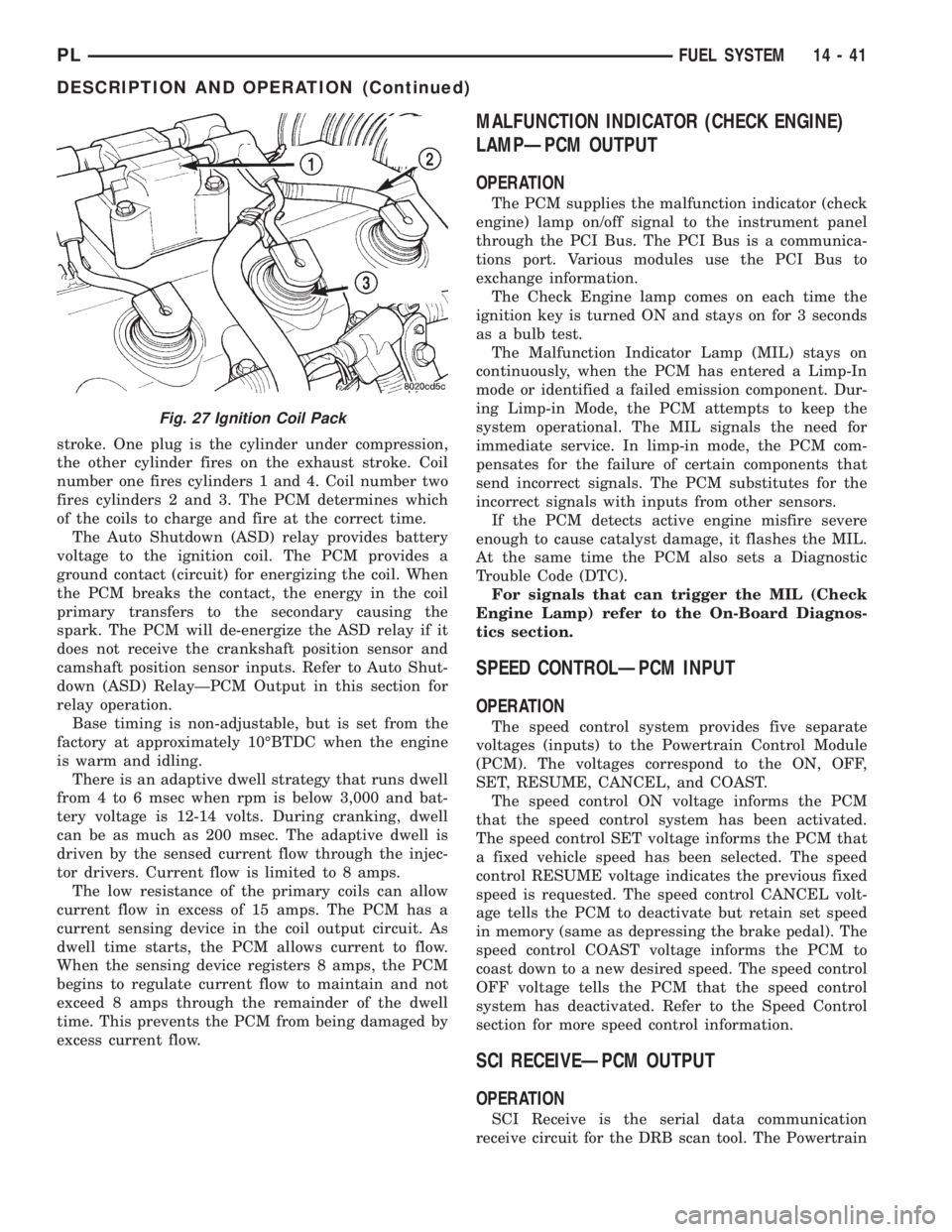
stroke. One plug is the cylinder under compression,
the other cylinder fires on the exhaust stroke. Coil
number one fires cylinders 1 and 4. Coil number two
fires cylinders 2 and 3. The PCM determines which
of the coils to charge and fire at the correct time.
The Auto Shutdown (ASD) relay provides battery
voltage to the ignition coil. The PCM provides a
ground contact (circuit) for energizing the coil. When
the PCM breaks the contact, the energy in the coil
primary transfers to the secondary causing the
spark. The PCM will de-energize the ASD relay if it
does not receive the crankshaft position sensor and
camshaft position sensor inputs. Refer to Auto Shut-
down (ASD) RelayÐPCM Output in this section for
relay operation.
Base timing is non-adjustable, but is set from the
factory at approximately 10ÉBTDC when the engine
is warm and idling.
There is an adaptive dwell strategy that runs dwell
from 4 to 6 msec when rpm is below 3,000 and bat-
tery voltage is 12-14 volts. During cranking, dwell
can be as much as 200 msec. The adaptive dwell is
driven by the sensed current flow through the injec-
tor drivers. Current flow is limited to 8 amps.
The low resistance of the primary coils can allow
current flow in excess of 15 amps. The PCM has a
current sensing device in the coil output circuit. As
dwell time starts, the PCM allows current to flow.
When the sensing device registers 8 amps, the PCM
begins to regulate current flow to maintain and not
exceed 8 amps through the remainder of the dwell
time. This prevents the PCM from being damaged by
excess current flow.
MALFUNCTION INDICATOR (CHECK ENGINE)
LAMPÐPCM OUTPUT
OPERATION
The PCM supplies the malfunction indicator (check
engine) lamp on/off signal to the instrument panel
through the PCI Bus. The PCI Bus is a communica-
tions port. Various modules use the PCI Bus to
exchange information.
The Check Engine lamp comes on each time the
ignition key is turned ON and stays on for 3 seconds
as a bulb test.
The Malfunction Indicator Lamp (MIL) stays on
continuously, when the PCM has entered a Limp-In
mode or identified a failed emission component. Dur-
ing Limp-in Mode, the PCM attempts to keep the
system operational. The MIL signals the need for
immediate service. In limp-in mode, the PCM com-
pensates for the failure of certain components that
send incorrect signals. The PCM substitutes for the
incorrect signals with inputs from other sensors.
If the PCM detects active engine misfire severe
enough to cause catalyst damage, it flashes the MIL.
At the same time the PCM also sets a Diagnostic
Trouble Code (DTC).
For signals that can trigger the MIL (Check
Engine Lamp) refer to the On-Board Diagnos-
tics section.
SPEED CONTROLÐPCM INPUT
OPERATION
The speed control system provides five separate
voltages (inputs) to the Powertrain Control Module
(PCM). The voltages correspond to the ON, OFF,
SET, RESUME, CANCEL, and COAST.
The speed control ON voltage informs the PCM
that the speed control system has been activated.
The speed control SET voltage informs the PCM that
a fixed vehicle speed has been selected. The speed
control RESUME voltage indicates the previous fixed
speed is requested. The speed control CANCEL volt-
age tells the PCM to deactivate but retain set speed
in memory (same as depressing the brake pedal). The
speed control COAST voltage informs the PCM to
coast down to a new desired speed. The speed control
OFF voltage tells the PCM that the speed control
system has deactivated. Refer to the Speed Control
section for more speed control information.
SCI RECEIVEÐPCM OUTPUT
OPERATION
SCI Receive is the serial data communication
receive circuit for the DRB scan tool. The Powertrain
Fig. 27 Ignition Coil Pack
PLFUEL SYSTEM 14 - 41
DESCRIPTION AND OPERATION (Continued)
Page 1110 of 1285
Pending ConditionsÐ
²Misfire DTC
²Front Oxygen Sensor Response
²Front Oxygen Sensor Heater Monitor
²Front Oxygen Sensor Electrical
²Rear Oxygen Sensor Rationality (middle check)
²Rear Oxygen Sensor Heater Monitor
²Rear Oxygen Sensor Electrical
²Fuel System Monitor
²All TPS faults
²All MAP faults
²All ECT sensor faults
²Purge flow solenoid functionality
²Purge flow solenoid electrical
²All PCM self test faults
²All CMP and CKP sensor faults
²All injector and ignition electrical faults
²Idle Air Control (IAC) motor functionality
²Vehicle Speed Sensor
²Brake switch
²Intake air temperature
ConflictÐThe catalyst monitor does not run if
any of the following are conditions are present:
²EGR Monitor in progress
²Fuel system rich intrusive test in progress
²EVAP Monitor in progress
²Time since start is less than 60 seconds
²Low fuel level
²Low ambient air temperature
SuspendÐThe Task Manager does not mature a
catalyst fault if any of the following are present:
²Oxygen Sensor Monitor, Priority 1
²Upstream Oxygen Sensor Heater, Priority 1
²EGR Monitor, Priority 1
²EVAP Monitor, Priority 1
²Fuel System Monitor, Priority 2
²Misfire Monitor, Priority 2
NON-MONITORED CIRCUITS
OPERATION
The PCM does not monitor all circuits, systems
and conditions that could have malfunctions causing
driveability problems. However, problems with these
systems may cause the PCM to store diagnostic trou-
ble codes for other systems or components. For exam-
ple, a fuel pressure problem will not register a fault
directly, but could cause a rich/lean condition or mis-
fire. This could cause the PCM to store an oxygen
sensor or misfire diagnostic trouble code.
The major non-monitored circuits are listed below
along with examples of failures modes that do not
directly cause the PCM to set a DTC, but for a sys-
tem that is monitored.FUEL PRESSURE
The fuel pressure regulator controls fuel system
pressure. The PCM cannot detect a clogged fuel
pump inlet filter, clogged in-line fuel filter, or a
pinched fuel supply or return line. However, these
could result in a rich or lean condition causing the
PCM to store an oxygen sensor or fuel system diag-
nostic trouble code.
SECONDARY IGNITION CIRCUIT
The PCM cannot detect an inoperative ignition coil,
fouled or worn spark plugs, ignition cross firing, or
open spark plug cables.
CYLINDER COMPRESSION
The PCM cannot detect uneven, low, or high engine
cylinder compression.
EXHAUST SYSTEM
The PCM cannot detect a plugged, restricted or
leaking exhaust system. It may set a EGR or Fuel
system fault or O2S.
FUEL INJECTOR MECHANICAL MALFUNCTIONS
The PCM cannot determine if a fuel injector is
clogged, the needle is sticking or if the wrong injector
is installed. However, these could result in a rich or
lean condition causing the PCM to store a diagnostic
trouble code for either misfire, an oxygen sensor, or
the fuel system.
EXCESSIVE OIL CONSUMPTION
Although the PCM monitors engine exhaust oxygen
content when the system is in closed loop, it cannot
determine excessive oil consumption.
THROTTLE BODY AIR FLOW
The PCM cannot detect a clogged or restricted air
cleaner inlet or filter element.
VACUUM ASSIST
The PCM cannot detect leaks or restrictions in the
vacuum circuits of vacuum assisted engine control
system devices. However, these could cause the PCM
to store a MAP sensor diagnostic trouble code and
cause a high idle condition.
PCM SYSTEM GROUND
The PCM cannot determine a poor system ground.
However, one or more diagnostic trouble codes may
be generated as a result of this condition. The mod-
ule should be mounted to the body at all times, also
during diagnostic.
PLEMISSION CONTROL SYSTEMS 25 - 23
DESCRIPTION AND OPERATION (Continued)