2000 DODGE NEON heating
[x] Cancel search: heatingPage 1 of 1285

GROUP TAB LOCATORINIntroductionINaIntroduction0Lubrication and Maintenance2Suspension3Differential and Driveline5Brakes6Clutch7Cooling8ABattery8BStarting8CCharging System8DIgnition System8EInstrument Panel and Systems8EaInstrument Panel and Systems8FAudio System8GHorns8HVehicle Speed Control System8JTurn Signal and Flashers8KWindshield Wipers and Washers8LLamps8LaLamps8MRestraint System8NElectrically Heated Systems8OPower Distribution Systems8PPower Door Locks8QImmobilizer System8SPower Windows8TPower Mirrors8TaPower Mirrors8UChime Warning/Reminder System8WWiring Diagrams - LHD and RHD9Engine11Exhaust System13Frame and Bumpers14Fuel System19Steering21Transaxle22Tires and Wheels23Body24Heating and Air Conditioning24aHeating and Air Conditioning25Emission Control Systems
Page 17 of 1285
SPECIFICATIONS in this section of this service
manual group.
(4) If the rear alignment is out of specification,
adjust it first before proceeding to the front.
CAMBER AND CASTER
Front and rear camber and caster settings on this
vehicle are determined at the time the vehicle is
designed, by the location of the vehicle's suspension
components. This is referred to as Net Build. The
result is no required adjustment of camber and
caster after the vehicle is built or when servicing the
suspension components. Thus, when performing a
wheel alignment, caster and camber are not normally
considered adjustable angles. Camber and caster
should be checked to ensure they meet vehicle speci-
fications.
If either front or rear camber is found not to meet
alignment specifications, it can be adjusted using an
available camber adjustment bolt package. Before
installing a camber adjustment bolt package on a
vehicle found to be outside the specifications, inspect
the suspension components for any signs of damage
or bending.
No adjustment can be made to the caster setting
on this vehicle. If the vehicle's caster is not within
alignment specifications, check for damaged suspen-
sion components or body parts.
CAUTION: Do not attempt to adjust the vehicles
wheel alignment by heating or bending any of the
suspension components.
CAMBER ADJUSTMENT BOLT PACKAGE INSTALLATION
NOTE: The following procedure should only be
used on vehicles without the ACR competition
package.
The camber adjustment bolt package contains new
bolts and nuts for attaching the strut clevis bracket
to the steering knuckle. The bolts contained in the
package are slightly undersize allowing for move-
ment between the strut clevis bracket and the steer-
ing knuckle. The movement allowed by the undersize
bolts provide approximately two degrees of camber
adjustment per side of the vehicle. To install and
adjust the camber adjustment bolt package, follow
the procedure below.
CAUTION: There are separate camber adjustment
bolt packages for the front and rear of the vehicle.
Be sure to use the correct package.
(1) Raise the vehicle until its tires are not support-
ing the weight of the vehicle.CAUTION: The knuckle to strut assembly attaching
bolt shanks are serrated and must not be turned
during removal. Remove the nuts while holding the
bolts stationary.
(2) Remove the original upper bolt attaching the
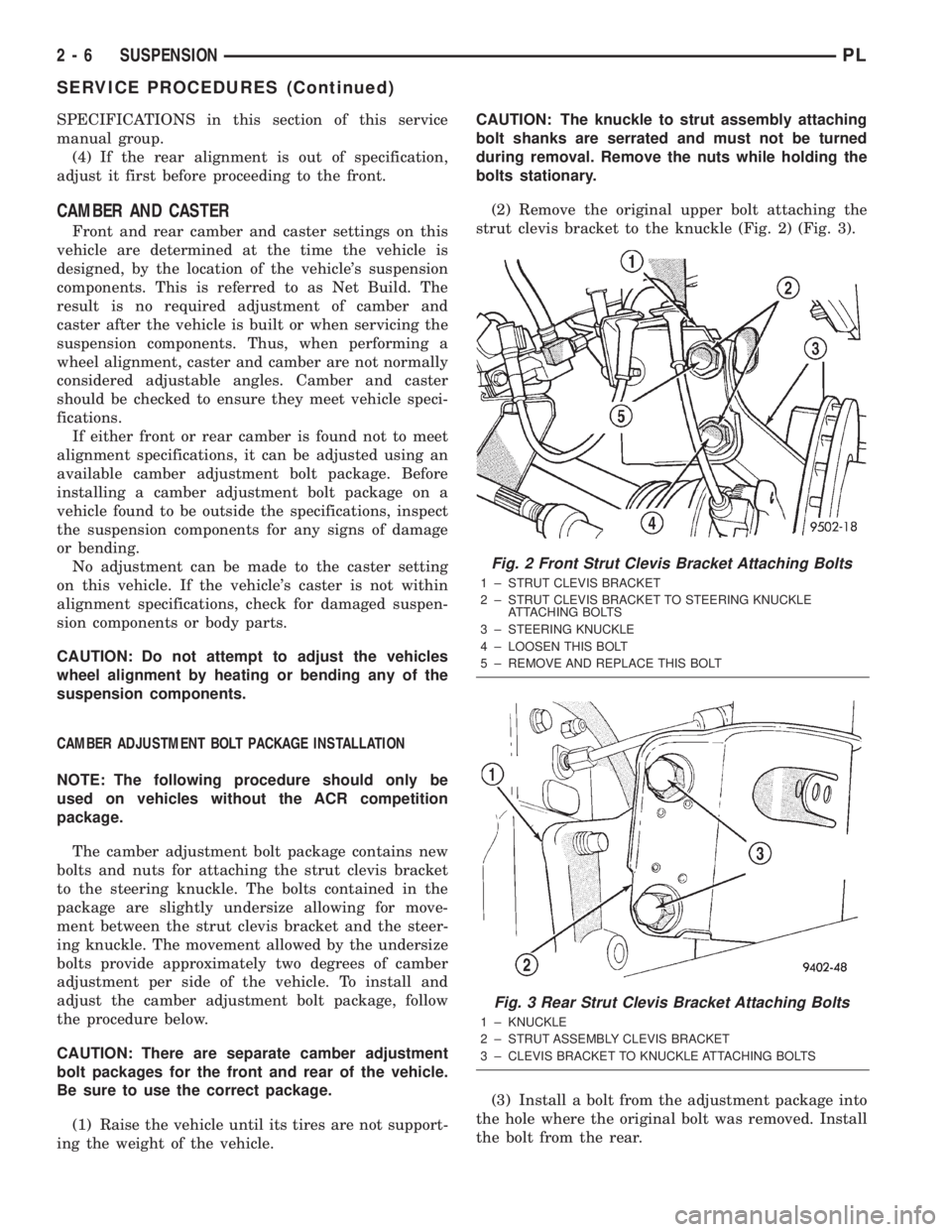
strut clevis bracket to the knuckle (Fig. 2) (Fig. 3).
(3) Install a bolt from the adjustment package into
the hole where the original bolt was removed. Install
the bolt from the rear.
Fig. 2 Front Strut Clevis Bracket Attaching Bolts
1 ± STRUT CLEVIS BRACKET
2 ± STRUT CLEVIS BRACKET TO STEERING KNUCKLE
ATTACHING BOLTS
3 ± STEERING KNUCKLE
4 ± LOOSEN THIS BOLT
5 ± REMOVE AND REPLACE THIS BOLT
Fig. 3 Rear Strut Clevis Bracket Attaching Bolts
1 ± KNUCKLE
2 ± STRUT ASSEMBLY CLEVIS BRACKET
3 ± CLEVIS BRACKET TO KNUCKLE ATTACHING BOLTS
2 - 6 SUSPENSIONPL
SERVICE PROCEDURES (Continued)
Page 139 of 1285
If the brake shoe assemblies do not require
replacement, reinstall the assemblies making sure
each brake shoe is returned to the original position.
Refer to DISC BRAKE SHOES in the REMOVAL
AND INSTALLATION section in this section of this
service manual group.
CALIPER INSPECTION
Check for brake fluid leaks in and around the boot
area. Check for any ruptures, brittleness or damage
to the piston dust boot. If the boot is damaged, or a
fluid leak is visible, disassemble the caliper assembly
and install a new seal and boot, and a piston if it is
scored. Refer to DISC BRAKE CALIPER in the DIS-
ASSEMBLY AND ASSEMBLY section in this section
of this service manual group.
Check the guide pin dust boots to determine if they
are in good condition. Replace if they are damaged,
dry, or found to be brittle. Refer to DISC BRAKE
CALIPER in the DISASSEMBLY AND ASSEMBLY
section in this section of this service manual group.
DISC BRAKES (REAR)
BRAKE SHOES
Clean the rear brake shoes and calipers with a
water-dampened cloth or with a brake cleaner. Do
not use a petroleum based product.
If a visual inspection does not adequately deter-
mine the condition of the lining, a physical check will
be necessary.
Remove the rear disc brake shoes. Refer to DISC
BRAKE SHOES in the REMOVAL AND INSTALLA-
TION section in this section of this service manual
group.
The combined brake shoe and lining material
thickness should be measured at the thinnest part of
the assembly.
When a set of brake shoes are worn to a total
thickness of approximately 7.0 mm (9/32 inch) or
less, they should be replaced.
Replace both brake shoe assemblies (inboard and
outboard). It is necessary that both front wheel sets
be replaced whenever brake shoe assemblies on
either side are replaced.
If the brake shoe assemblies do not require
replacement, reinstall the assemblies making sure
each brake shoe is returned to the original position.
Refer to DISC BRAKE SHOES in the REMOVAL
AND INSTALLATION section in this section of this
service manual group.
CALIPER INSPECTION
Check for brake fluid leaks in and around the boot
area. Check for any ruptures, brittleness or damage
to the piston dust boot. If the boot is damaged, or afluid leak is visible, disassemble the caliper assembly
and install a new seal and boot, and a piston if it is
scored. Refer to DISC BRAKE CALIPER in the DIS-
ASSEMBLY AND ASSEMBLY section in this section
of this service manual group.
Check the guide pin dust boots to determine if they
are in good condition. Replace if they are damaged,
dry, or found to be brittle. Refer to DISC BRAKE
CALIPER in the DISASSEMBLY AND ASSEMBLY
section in this section of this service manual group.
DRUM BRAKES (REAR)
BRAKE SHOES
Clean the rear brake shoes and springs with a
water-dampened cloth or with a brake cleaner. Do
not use a petroleum based product.
Rear brake shoe lining should show contact across
the entire width of the lining and also from the heel
to the toe of the lining. Replace the shoes if noted
otherwise.
Brake shoes with lack of contact at the toe or heel
of the brake shoe lining may be improperly ground.
Clean and inspect the brake support plate and
shoe adjuster screw. Apply a thin coat of Mopart
Multi-Purpose Lubricant or equivalent to the threads
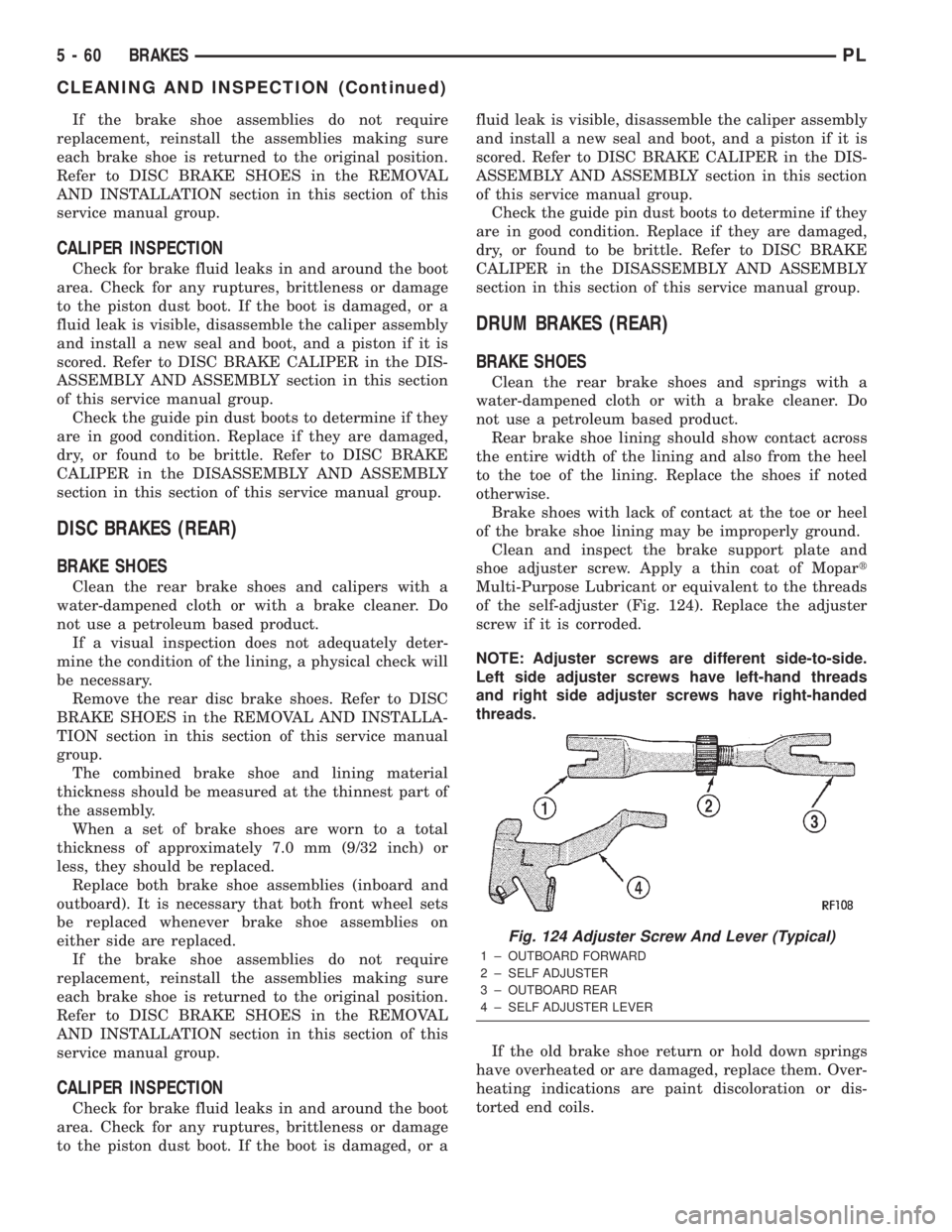
of the self-adjuster (Fig. 124). Replace the adjuster
screw if it is corroded.
NOTE: Adjuster screws are different side-to-side.
Left side adjuster screws have left-hand threads
and right side adjuster screws have right-handed
threads.
If the old brake shoe return or hold down springs
have overheated or are damaged, replace them. Over-
heating indications are paint discoloration or dis-
torted end coils.
Fig. 124 Adjuster Screw And Lever (Typical)
1 ± OUTBOARD FORWARD
2 ± SELF ADJUSTER
3 ± OUTBOARD REAR
4 ± SELF ADJUSTER LEVER
5 - 60 BRAKESPL
CLEANING AND INSPECTION (Continued)
Page 168 of 1285
SERVICE DIAGNOSISÐCLUTCH GRAB/CHATTER
CONDITION POSSIBLE CAUSES CORRECTION
CLUTCH DISC
FACING COVERED
WITH OIL OR
GREASEOil leak at engine rear main or transaxle
input shaft sealCorrect leak and replace modular clutch
assembly
Too much grease applied to splines of disc
and input shaftApply lighter coating of grease to splines
NO FAULT FOUND
WITH CLUTCH
COMPONENTSProblem actually related to suspension or
driveline componentFurther diagnosis required. Check
engine/transmission mounts, suspension
attaching parts and other driveline
components as needed.
Engine related problems Check EFI and ignition systems
PARTIAL
ENGAGEMENT OF
CLUTCH DISCClutch cover, spring, or release fingers
bent, distorted (rough handling, improper
assembly)Replace modular clutch assembly
Clutch disc damaged or distorted Replace modular clutch assembly
Clutch misalignment Check alignment and runout of flywheel,
disc, or cover. Check clutch housing to
engine dowels and dowel holes for damage.
Correct as necessary.
SERVICE DIAGNOSISÐCLUTCH SLIPS
CONDITION POSSIBLE CAUSES CORRECTION
DISC FACING
WORN OUTNormal wear. Replace modular clutch assembly.
Driver frequently rides (slips) clutch, results
in rapid wear overheating.Replace modular clutch assembly
Insufficient clutch cover diaphragm spring
tensionReplace modular clutch assembly
CLUTCH DISC
FACING
CONTAMINATED
WITH OIL OR
GREASELeak at rear main oil seal or transaxle input
shaft sealReplace leaking seals. Replace modular
clutch assembly.
Excessive amount of grease applied to
input shaft splinesApply less grease to input shaft. Replace
modular clutch assembly
Road splash, water entering housing Seal housing. Inspect clutch assembly.
CLUTCH IS
RUNNING
PARTIALLY
DISENGAGEDRelease bearing sticking or binding, does
not return to normal running position.Verify that bearing is actually binding. Then,
replace bearing and transmission front
bearing retainer if sleeve surface is
damaged.
Cable self-adjuster mechanism sticking or
binding causing high preloadVerify that self-adjuster is free to move
PLCLUTCH 6 - 3
DIAGNOSIS AND TESTING (Continued)
Page 185 of 1285
AUTOMATIC TRANSMISSION OIL COOLER
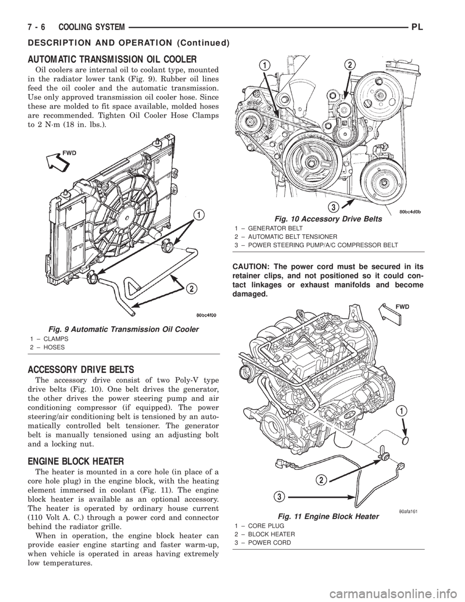
Oil coolers are internal oil to coolant type, mounted
in the radiator lower tank (Fig. 9). Rubber oil lines
feed the oil cooler and the automatic transmission.
Use only approved transmission oil cooler hose. Since
these are molded to fit space available, molded hoses
are recommended. Tighten Oil Cooler Hose Clamps
to 2 N´m (18 in. lbs.).
ACCESSORY DRIVE BELTS
The accessory drive consist of two Poly-V type
drive belts (Fig. 10). One belt drives the generator,
the other drives the power steering pump and air
conditioning compressor (if equipped). The power
steering/air conditioning belt is tensioned by an auto-
matically controlled belt tensioner. The generator
belt is manually tensioned using an adjusting bolt
and a locking nut.
ENGINE BLOCK HEATER
The heater is mounted in a core hole (in place of a
core hole plug) in the engine block, with the heating
element immersed in coolant (Fig. 11). The engine
block heater is available as an optional accessory.
The heater is operated by ordinary house current
(110 Volt A. C.) through a power cord and connector
behind the radiator grille.
When in operation, the engine block heater can
provide easier engine starting and faster warm-up,
when vehicle is operated in areas having extremely
low temperatures.CAUTION: The power cord must be secured in its
retainer clips, and not positioned so it could con-
tact linkages or exhaust manifolds and become
damaged.
Fig. 9 Automatic Transmission Oil Cooler
1 ± CLAMPS
2 ± HOSES
Fig. 10 Accessory Drive Belts
1 ± GENERATOR BELT
2 ± AUTOMATIC BELT TENSIONER
3 ± POWER STEERING PUMP/A/C COMPRESSOR BELT
Fig. 11 Engine Block Heater
1 ± CORE PLUG
2 ± BLOCK HEATER
3 ± POWER CORD
7 - 6 COOLING SYSTEMPL
DESCRIPTION AND OPERATION (Continued)
Page 186 of 1285
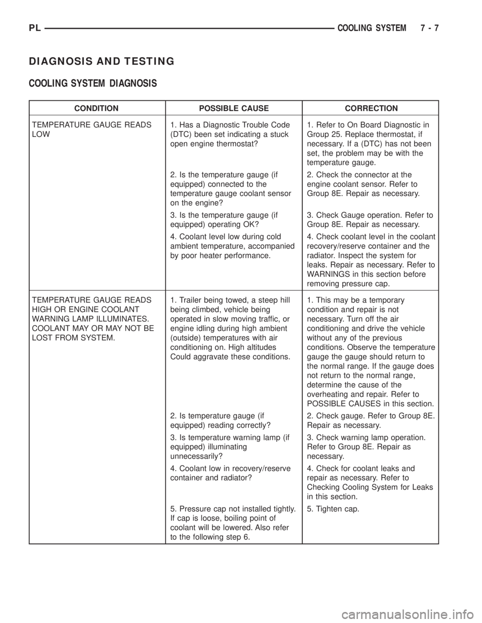
DIAGNOSIS AND TESTING
COOLING SYSTEM DIAGNOSIS
CONDITION POSSIBLE CAUSE CORRECTION
TEMPERATURE GAUGE READS
LOW1. Has a Diagnostic Trouble Code
(DTC) been set indicating a stuck
open engine thermostat?1. Refer to On Board Diagnostic in
Group 25. Replace thermostat, if
necessary. If a (DTC) has not been
set, the problem may be with the
temperature gauge.
2. Is the temperature gauge (if
equipped) connected to the
temperature gauge coolant sensor
on the engine?2. Check the connector at the
engine coolant sensor. Refer to
Group 8E. Repair as necessary.
3. Is the temperature gauge (if
equipped) operating OK?3. Check Gauge operation. Refer to
Group 8E. Repair as necessary.
4. Coolant level low during cold
ambient temperature, accompanied
by poor heater performance.4. Check coolant level in the coolant
recovery/reserve container and the
radiator. Inspect the system for
leaks. Repair as necessary. Refer to
WARNINGS in this section before
removing pressure cap.
TEMPERATURE GAUGE READS
HIGH OR ENGINE COOLANT
WARNING LAMP ILLUMINATES.
COOLANT MAY OR MAY NOT BE
LOST FROM SYSTEM.1. Trailer being towed, a steep hill
being climbed, vehicle being
operated in slow moving traffic, or
engine idling during high ambient
(outside) temperatures with air
conditioning on. High altitudes
Could aggravate these conditions.1. This may be a temporary
condition and repair is not
necessary. Turn off the air
conditioning and drive the vehicle
without any of the previous
conditions. Observe the temperature
gauge the gauge should return to
the normal range. If the gauge does
not return to the normal range,
determine the cause of the
overheating and repair. Refer to
POSSIBLE CAUSES in this section.
2. Is temperature gauge (if
equipped) reading correctly?2. Check gauge. Refer to Group 8E.
Repair as necessary.
3. Is temperature warning lamp (if
equipped) illuminating
unnecessarily?3. Check warning lamp operation.
Refer to Group 8E. Repair as
necessary.
4. Coolant low in recovery/reserve
container and radiator?4. Check for coolant leaks and
repair as necessary. Refer to
Checking Cooling System for Leaks
in this section.
5. Pressure cap not installed tightly.
If cap is loose, boiling point of
coolant will be lowered. Also refer
to the following step 6.5. Tighten cap.
PLCOOLING SYSTEM 7 - 7
Page 188 of 1285
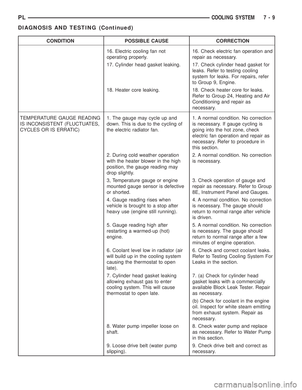
CONDITION POSSIBLE CAUSE CORRECTION
16. Electric cooling fan not
operating properly.16. Check electric fan operation and
repair as necessary.
17. Cylinder head gasket leaking. 17. Check cylinder head gasket for
leaks. Refer to testing cooling
system for leaks. For repairs, refer
to Group 9, Engine.
18. Heater core leaking. 18. Check heater core for leaks.
Refer to Group 24, Heating and Air
Conditioning and repair as
necessary.
TEMPERATURE GAUGE READING
IS INCONSISTENT (FLUCTUATES,
CYCLES OR IS ERRATIC)1. The gauge may cycle up and
down. This is due to the cycling of
the electric radiator fan.1. A normal condition. No correction
is necessary. If gauge cycling is
going into the hot zone, check
electric fan operation and repair as
necessary. Refer to procedure in
this section.
2. During cold weather operation
with the heater blower in the high
position, the gauge reading may
drop slightly.2. A normal condition. No correction
is necessary.
3, Temperature gauge or engine
mounted gauge sensor is defective
or shorted.3. Check operation of gauge and
repair as necessary. Refer to Group
8E, Instrument Panel and Gauges.
4. Gauge reading rises when
vehicle is brought to a stop after
heavy use (engine still running).4. A normal condition. No correction
is necessary. The gauge should
return to normal range after vehicle
is driven.
5. Gauge reading high after
restarting a warmed-up (hot)
engine.5. A normal condition. No correction
is necessary. The gauge should
return to normal range after a few
minutes of engine operation.
6. Coolant level low in radiator (air
will build up in the cooling system
causing the thermostat to open
late).6. Check and correct coolant leaks.
Refer to Testing Cooling System For
Leaks in the section.
7. Cylinder head gasket leaking
allowing exhaust gas to enter
cooling system. This will cause
thermostat to open late.7. (a) Check for cylinder head
gasket leaks with a commercially
available Block Leak Tester. Repair
as necessary.
(b) Check for coolant in the engine
oil. Inspect for white steam emitting
from exhaust system. Repair as
necessary.
8. Water pump impeller loose on
shaft.8. Check water pump and replace
as necessary. Refer to Water Pump
in this section.
9. Loose drive belt (water pump
slipping).9. Check drive belt and correct as
necessary.
PLCOOLING SYSTEM 7 - 9
DIAGNOSIS AND TESTING (Continued)
Page 189 of 1285
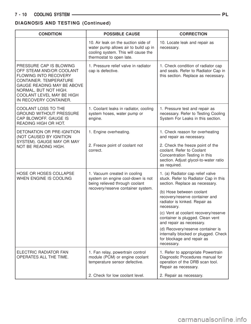
CONDITION POSSIBLE CAUSE CORRECTION
10. Air leak on the suction side of
water pump allows air to build up in
cooling system. This will cause the
thermostat to open late.10. Locate leak and repair as
necessary.
PRESSURE CAP IS BLOWING
OFF STEAM AND/OR COOLANT
FLOWING INTO RECOVERY
CONTAINER. TEMPERATURE
GAUGE READING MAY BE ABOVE
NORMAL, BUT NOT HIGH.
COOLANT LEVEL MAY BE HIGH
IN RECOVERY CONTAINER.1. Pressure relief valve in radiator
cap is defective.1. Check condition of radiator cap
and seals. Refer to Radiator Cap in
this section. Replace as necessary.
COOLANT LOSS TO THE
GROUND WITHOUT PRESSURE
CAP BLOWOFF. GAUGE IS
READING HIGH OR HOT.1. Coolant leaks in radiator, cooling
system hoses, water pump or
engine.1. Pressure test and repair as
necessary. Refer to Testing Cooling
System For Leaks in this section.
DETONATION OR PRE-IGNITION
(NOT CAUSED BY IGNITION
SYSTEM). GAUGE MAY OR MAY
NOT BE READING HIGH.1. Engine overheating. 1. Check reason for overheating
and repair as necessary.
2. Freeze point of coolant not
correct.2. Check the freeze point of the
coolant. Refer to Coolant
Concentration Testing in this
section. Adjust glycol-to-water ratio
as required.
HOSE OR HOSES COLLAPSE
WHEN ENGINE IS COOLING1. Vacuum created in cooling
system on engine cool-down is not
being relieved through coolant
recovery/reserve container system.1. (a) Radiator cap relief valve
stuck. Refer to Radiator Cap in this
section. Replace as necessary.
(b) Hose between coolant
recovery/reserve container and
radiator is kinked. Repair as
necessary.
(c) Vent at coolant recovery/reserve
container is plugged. Clean vent
and repair as necessary.
(d) Recovery/reserve container is
internally blocked or plugged. Check
for blockage and repair as
necessary.
ELECTRIC RADIATOR FAN
OPERATES ALL THE TIME.1. Fan relay, powertrain control
module (PCM) or engine coolant
temperature sensor defective.1. Refer to appropriate Powertrain
Diagnostic Procedures manual for
operation of the DRB scan tool.
Repair as necessary.
2. Check for low coolant level. 2. Repair as necessary.
7 - 10 COOLING SYSTEMPL
DIAGNOSIS AND TESTING (Continued)