2000 DODGE NEON remove seats
[x] Cancel search: remove seatsPage 22 of 1285
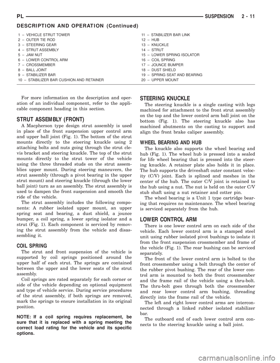
For more information on the description and oper-
ation of an individual component, refer to the appli-
cable component heading in this section.
STRUT ASSEMBLY (FRONT)
A Macpherson type design strut assembly is used
in place of the front suspension upper control arm
and upper ball joint (Fig. 1). The bottom of the strut
mounts directly to the steering knuckle using 2
attaching bolts and nuts going through the strut cle-
vis bracket and steering knuckle. The top of the strut
mounts directly to the strut tower of the vehicle
using the three threaded studs on the strut assem-
blies upper mount. During steering maneuvers, the
strut assembly (through a pivot bearing in the upper
strut mount) and steering knuckle (through the lower
ball joint) turn as an assembly. The strut assembly is
used to dampen the front suspension and smooth the
ride of the vehicle.
The strut assembly includes the following compo-
nents: A rubber isolated upper mount, an upper
spring seat and bearing, a dust shield, a jounce
bumper, a coil spring, a lower spring isolator and a
strut (Fig. 1). Each component is serviced by remov-
ing the strut assembly from the vehicle and disas-
sembling it.
COIL SPRING
The strut and front suspension of the vehicle is
supported by coil springs positioned around the
upper half of each strut. The springs are contained
between the upper and the lower seats of the strut
assembly.
Coil springs are rated separately for each corner or
side of the vehicle depending on optional equipment
and type of vehicle service. During service procedures
of the strut assembly, if both springs are removed,
mark the springs to ensure installation in its original
position.
NOTE: If a coil spring requires replacement, be
sure that it is replaced with a spring meeting the
correct load rating for the vehicle and its specific
options.
STEERING KNUCKLE
The steering knuckle is a single casting with legs
machined for attachment to the front strut assembly
on the top and the lower control arm ball joint on the
bottom (Fig. 1). The steering knuckle also has
machined abutments on the casting to support and
align the front brake caliper assembly.
WHEEL BEARING AND HUB
The knuckle also supports the wheel bearing and
hub (Fig. 1). The wheel hub is pressed into a sealed
for life wheel bearing that is pressed into the steer-
ing knuckle. A retainer plate also holds it in place.
The hub supports the driveshaft outer constant veloc-
ity (C/V) joint. Each is splined and meshes in the
center of the hub. The outer C/V joint is retained to
the hub using a nut. The nut is held on the outer C/V
stub shaft using a nut retainer and cotter pin.
The wheel bearing is a Unit 1 type cartridge bear-
ing that requires no maintenance. The wheel bearing
is serviced separately from the hub.
LOWER CONTROL ARM
There is one lower control arm on each side of the
vehicle. Each lower control arm is a stamped steel
unit using rubber isolated pivot bushings to isolate it
from the front suspension crossmember and frame of
the vehicle (Fig. 1). The rear bushing can be serviced
separately.
The front of the lower control arm is bolted to the
front crossmember using a bolt through the center of
the rubber pivot bushing. The rear of the lower con-
trol arm is mounted to both the front crossmember
and the frame rail of the vehicle using a thru-bolt.
The thru-bolt goes through both the crossmember
and rear lower control arm bushing, threading
directly into the frame rail of the vehicle.
The left and right lower control arms are intercon-
nected through a linked rubber isolated stabilizer
bar.
The outboard end of each lower control arm con-
nects to the steering knuckle using a ball joint.
1 ± VEHICLE STRUT TOWER
2 ± OUTER TIE ROD
3 ± STEERING GEAR
4 ± STRUT ASSEMBLY
5 ± JAM NUT
6 ± LOWER CONTROL ARM
7 ± CROSSMEMBER
8 ± BALL JOINT
9 ± STABILIZER BAR
10 ± STABILIZER BAR CUSHION AND RETAINER11 ± STABILIZER BAR LINK
12 ± HUB
13 ± KNUCKLE
14 ± STRUT
15 ± LOWER SPRING ISOLATOR
16 ± COIL SPRING
17 ± JOUNCE BUMPER
18 ± DUST SHIELD
19 ± SPRING SEAT AND BEARING
20 ± UPPER MOUNT
PLSUSPENSION 2 - 11
DESCRIPTION AND OPERATION (Continued)
Page 175 of 1285
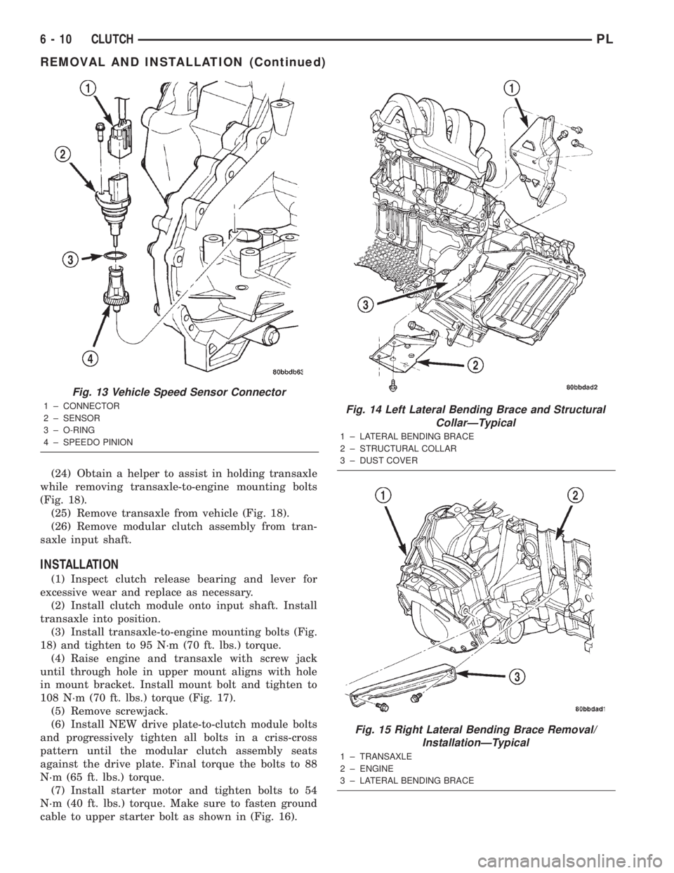
(24) Obtain a helper to assist in holding transaxle
while removing transaxle-to-engine mounting bolts
(Fig. 18).
(25) Remove transaxle from vehicle (Fig. 18).
(26) Remove modular clutch assembly from tran-
saxle input shaft.
INSTALLATION
(1) Inspect clutch release bearing and lever for
excessive wear and replace as necessary.
(2) Install clutch module onto input shaft. Install
transaxle into position.
(3) Install transaxle-to-engine mounting bolts (Fig.
18) and tighten to 95 N´m (70 ft. lbs.) torque.
(4) Raise engine and transaxle with screw jack
until through hole in upper mount aligns with hole
in mount bracket. Install mount bolt and tighten to
108 N´m (70 ft. lbs.) torque (Fig. 17).
(5) Remove screwjack.
(6) Install NEW drive plate-to-clutch module bolts
and progressively tighten all bolts in a criss-cross
pattern until the modular clutch assembly seats
against the drive plate. Final torque the bolts to 88
N´m (65 ft. lbs.) torque.
(7) Install starter motor and tighten bolts to 54
N´m (40 ft. lbs.) torque. Make sure to fasten ground
cable to upper starter bolt as shown in (Fig. 16).
Fig. 13 Vehicle Speed Sensor Connector
1 ± CONNECTOR
2 ± SENSOR
3 ± O-RING
4 ± SPEEDO PINIONFig. 14 Left Lateral Bending Brace and Structural
CollarÐTypical
1 ± LATERAL BENDING BRACE
2 ± STRUCTURAL COLLAR
3 ± DUST COVER
Fig. 15 Right Lateral Bending Brace Removal/
InstallationÐTypical
1 ± TRANSAXLE
2 ± ENGINE
3 ± LATERAL BENDING BRACE
6 - 10 CLUTCHPL
REMOVAL AND INSTALLATION (Continued)
Page 254 of 1285

INSTRUMENT CLUSTER LAMPS
WARNINGS/INDICATORS
The instrument cluster warning/indicator lamps
are all serviceable Light Emitting Diodes (LED's).
The instrument cluster must first be removed, refer
to Instrument Cluster Removal and Installation in
this section, and then the defective LED just turns
out with needle nose pliers.
ILLUMINATION LAMPS
The high beam indicator, turn signals, and illumi-
nation bulbs are also serviceable. The instrument
cluster must first be removed, refer to Instrument
Cluster Removal and Installation in this section, and
then the defective bulb and socket turns out. The
bulb locations are printed on the back cover of the
instrument cluster.
INSTRUMENT PANEL ASSEMBLY
REMOVAL
(1) Disconnect and isolate the battery negative
cable (Fig. 6).
(2) Push seats back to their full back position.
(3) Using a trim stick (special tool #C-4755), gently
pry out on left and right A-pillar trim moldings and
remove.
(4) Remove top cover. Refer to Top Cover Removal
and Installation in this section.
(5) Gently pull up on cluster bezel and remove
from vehicle.
(6) Gently pull rearward on left lower instrument
panel cover and remove from vehicle.
CAUTION: Lock the steering wheel in the straight
ahead position. This will prevent clockspring dam-
age when the steering wheel rotates freely.
(7) Remove steering column. Refer to Group 19
Steering, Steering Column Removal and Installation.
(8) Remove left and right instrument panel end-
caps.
(9) Remove left and right cowl side panels.
(10) Remove center console. Refer to Group 23
Body, Center Console Removal and Installation.
(11) Depress the sides of the Data Link Connector
(DLC) and remove from instrument panel reinforce-
ment.
(12) Remove four bulkhead instrument panel
retaining screws.
(13) Remove two bolts on top of the brake pedal
support bracket.
(14) Remove two center support mounting bolts.
(15) Remove left and right A-pillar mounting bolts,
two on each side.(16) Disconnect right side antenna connector.
(17) Remove left and right A-pillar door harness
connectors (Fig. 10).
(18) Disconnect two harness connectors to hvac at
right top instrument panel (Fig. 11).
Fig. 10 A-Pillar Door Harness Connector
1 ± INSTRUMENT PANEL HARNESS CONNECTOR
2 ± DOOR CHECK STRAP
3 ± DOOR HARNESS CONNECTOR
Fig. 11 Instrument Panel to HVAC Harness Connectors
1 ± HVAC HARNESS CONNECTORS
PLINSTRUMENT PANEL SYSTEMS 8E - 7
REMOVAL AND INSTALLATION (Continued)
Page 1082 of 1285
METHOD 2 (RELOCATE TIRE ON WHEEL)
Rotating tire on wheel is particularly effective
when there is run out in both tire and wheel.
Remove tire from wheel and remount wheel on hub
in former position.
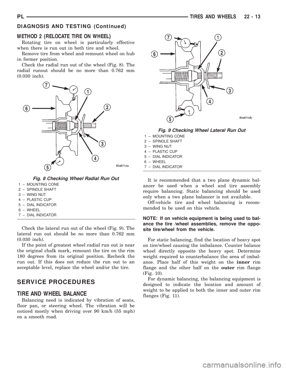
Check the radial run out of the wheel (Fig. 8). The
radial runout should be no more than 0.762 mm
(0.030 inch).
Check the lateral run out of the wheel (Fig. 9). The
lateral run out should be no more than 0.762 mm
(0.030 inch).
If the point of greatest wheel radial run out is near
the original chalk mark, remount the tire on the rim
180 degrees from its original position. Recheck the
run out. If this does not reduce the run out to an
acceptable level, replace the wheel and/or the tire.
SERVICE PROCEDURES
TIRE AND WHEEL BALANCE
Balancing need is indicated by vibration of seats,
floor pan, or steering wheel. The vibration will be
noticed mostly when driving over 90 km/h (55 mph)
on a smooth road.It is recommended that a two plane dynamic bal-
ancer be used when a wheel and tire assembly
require balancing. Static balancing should be used
only when a two plane balancer is not available.
Off-vehicle tire and wheel balancing is recom-
mended to be used on this vehicle.
NOTE: If on vehicle equipment is being used to bal-
ance the tire /wheel assemblies, remove the oppo-
site tire/wheel from the vehicle.
For static balancing, find the location of heavy spot
on tire/wheel causing the imbalance. Counter balance
wheel directly opposite the heavy spot. Determine
weight required to counterbalance the area of imbal-
ance. Place half of this weight on theinnerrim
flange and the other half on theouterrim flange
(Fig. 10).
For dynamic balancing, the balancing equipment is
designed to indicate the location and amount of
weight to be applied to both the inner and outer rim
flanges (Fig. 11).
Fig. 8 Checking Wheel Radial Run Out
1 ± MOUNTING CONE
2 ± SPINDLE SHAFT
3 ± WING NUT
4 ± PLASTIC CUP
5 ± DIAL INDICATOR
6 ± WHEEL
7 ± DIAL INDICATOR
Fig. 9 Checking Wheel Lateral Run Out
1 ± MOUNTING CONE
2 ± SPINDLE SHAFT
3 ± WING NUT
4 ± PLASTIC CUP
5 ± DIAL INDICATOR
6 ± WHEEL
7 ± DIAL INDICATOR
PLTIRES AND WHEELS 22 - 13
DIAGNOSIS AND TESTING (Continued)
Page 1118 of 1285
BODY
TABLE OF CONTENTS
page page
PAINT................................... 1
STATIONARY GLASS........................ 4
SEATS ................................... 8BODY COMPONENTS...................... 12
SPECIFICATIONS......................... 60
PAINT
TABLE OF CONTENTS
page page
DESCRIPTION AND OPERATION
PAINT CODE.............................1
BASE COAT/CLEAR COAT FINISH.............1
WET SANDING, BUFFING, AND POLISHING.....1PAINTED SURFACE TOUCH-UP..............1
SPECIFICATIONS
AFTERMARKET PAINT REPAIR PRODUCTS.....2
DESCRIPTION AND OPERATION
PAINT CODE
A paint code is provided on the body code plate
located in the engine compartment. Refer to the
Introduction section at the front of this manual for
body code plate description. The paint and trim codes
are also included on the Vehicle Safety Label located
on the driver's door end frame.
BASE COAT/CLEAR COAT FINISH
On most vehicles a two-part paint application (base
coat/clear coat) is used. Color paint that is applied to
primer is called base coat. The clear coat protects the
base coat from ultraviolet light and provides a dura-
ble high-gloss finish.
CAUTION: Do not use abrasive chemicals or com-
pounds on painted surfaces. Damage to finish can
result.
Do not use harsh alkaline based cleaning sol-
vents on painted surfaces. Damage to finish or
color can result.
WET SANDING, BUFFING, AND POLISHING
Minor acid etching, orange peel, or smudging in
clear coat or single-stage finishes can be reduced
with light wet sanding, hand buffing, and polishing.
If the finish has been wet sanded in the past, itcannot be repeated. Wet sanding operation
should be performed by a trained automotive
paint technician.
CAUTION: Do not remove clear coat finish, if
equipped. Base coat paint must retain clear coat for
durability.
PAINTED SURFACE TOUCH-UP
When a painted metal surface has been scratched
or chipped, it should be touched-up as soon as possi-
ble to avoid corrosion. For best results, use Mopart
Scratch Filler/Primer, Touch-Up Paints and Clear Top
Coat. Refer to Introduction group of this manual for
Body Code Plate information.
CAUTION: USE A OSHA APPROVED BREATHING
FILTER WHEN SPRAYING PAINT OR SOLVENTS IN
A CONFINED AREA. PERSONAL INJURY CAN
RESULT.
TOUCH-UP PROCEDURE
(1) Scrape loose paint and corrosion from inside
scratch or chip.
(2) Clean affected area with MopartTar/Road Oil
Remover, and allow to dry.
(3) Fill the inside of the scratch or chip with a coat
of filler/primer. Do not overlap primer onto good sur-
PLBODY 23 - 1
Page 1125 of 1285
SEATS
TABLE OF CONTENTS
page page
REMOVAL AND INSTALLATION
FRONT SEAT.............................8
FRONT SEAT BACK........................8
FRONT SEAT BACK COVER.................9FRONT SEAT CUSHION COVER..............9
FRONT SEAT CUSHION....................9
REAR SEAT BACK........................10
REAR SEAT CUSHION.....................11
REMOVAL AND INSTALLATION
FRONT SEAT
REMOVAL
(1) Move seat to forward position.
(2) Remove bolts attaching rear of seat track to
floor.
(3) Move seat to rearward position.
(4) Remove bolts attaching front of seat track to
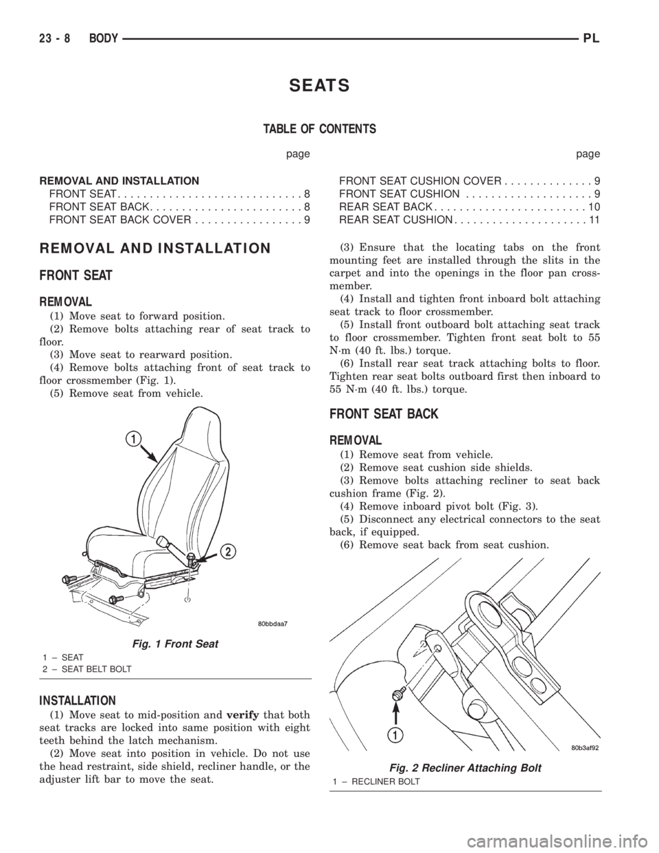
floor crossmember (Fig. 1).
(5) Remove seat from vehicle.
INSTALLATION
(1) Move seat to mid-position andverifythat both
seat tracks are locked into same position with eight
teeth behind the latch mechanism.
(2) Move seat into position in vehicle. Do not use
the head restraint, side shield, recliner handle, or the
adjuster lift bar to move the seat.(3) Ensure that the locating tabs on the front
mounting feet are installed through the slits in the
carpet and into the openings in the floor pan cross-
member.
(4) Install and tighten front inboard bolt attaching
seat track to floor crossmember.
(5) Install front outboard bolt attaching seat track
to floor crossmember. Tighten front seat bolt to 55
N´m (40 ft. lbs.) torque.
(6) Install rear seat track attaching bolts to floor.
Tighten rear seat bolts outboard first then inboard to
55 N´m (40 ft. lbs.) torque.
FRONT SEAT BACK
REMOVAL
(1) Remove seat from vehicle.
(2) Remove seat cushion side shields.
(3) Remove bolts attaching recliner to seat back
cushion frame (Fig. 2).
(4) Remove inboard pivot bolt (Fig. 3).
(5) Disconnect any electrical connectors to the seat
back, if equipped.
(6) Remove seat back from seat cushion.
Fig. 1 Front Seat
1 ± SEAT
2 ± SEAT BELT BOLT
Fig. 2 Recliner Attaching Bolt
1 ± RECLINER BOLT
23 - 8 BODYPL
Page 1173 of 1285
(3) Remove rear seat closure panel silencer pad as
necessary to gain access to retractor.
(4) Remove bolt attaching seat belt lower anchor to
floor.
(5) Remove bolt attaching retractor to rear seat
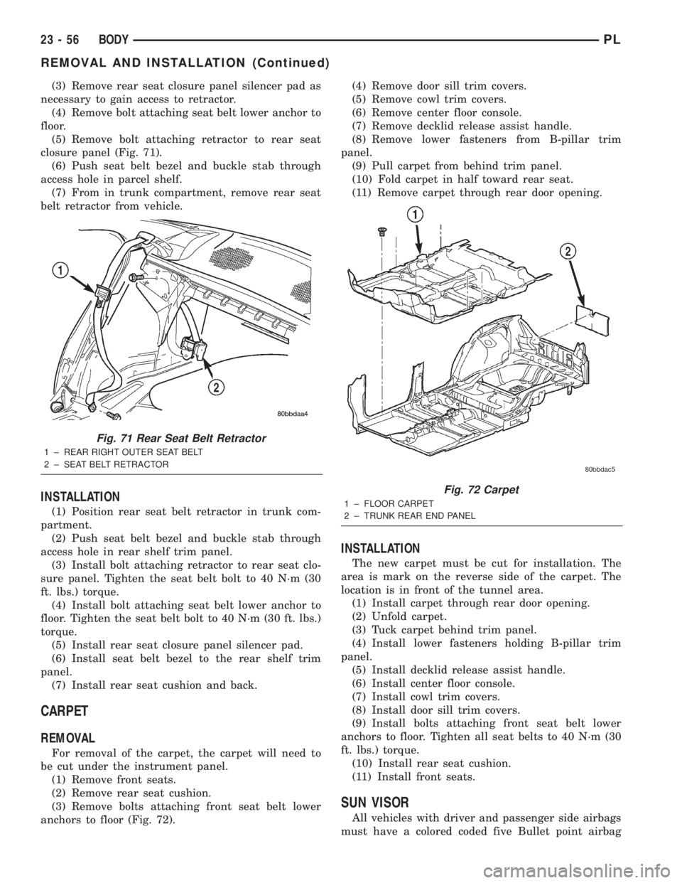
closure panel (Fig. 71).
(6) Push seat belt bezel and buckle stab through
access hole in parcel shelf.
(7) From in trunk compartment, remove rear seat
belt retractor from vehicle.
INSTALLATION
(1) Position rear seat belt retractor in trunk com-
partment.
(2) Push seat belt bezel and buckle stab through
access hole in rear shelf trim panel.
(3) Install bolt attaching retractor to rear seat clo-
sure panel. Tighten the seat belt bolt to 40 N´m (30
ft. lbs.) torque.
(4) Install bolt attaching seat belt lower anchor to
floor. Tighten the seat belt bolt to 40 N´m (30 ft. lbs.)
torque.
(5) Install rear seat closure panel silencer pad.
(6) Install seat belt bezel to the rear shelf trim
panel.
(7) Install rear seat cushion and back.
CARPET
REMOVAL
For removal of the carpet, the carpet will need to
be cut under the instrument panel.
(1) Remove front seats.
(2) Remove rear seat cushion.
(3) Remove bolts attaching front seat belt lower
anchors to floor (Fig. 72).(4) Remove door sill trim covers.
(5) Remove cowl trim covers.
(6) Remove center floor console.
(7) Remove decklid release assist handle.
(8) Remove lower fasteners from B-pillar trim
panel.
(9) Pull carpet from behind trim panel.
(10) Fold carpet in half toward rear seat.
(11) Remove carpet through rear door opening.
INSTALLATION
The new carpet must be cut for installation. The
area is mark on the reverse side of the carpet. The
location is in front of the tunnel area.
(1) Install carpet through rear door opening.
(2) Unfold carpet.
(3) Tuck carpet behind trim panel.
(4) Install lower fasteners holding B-pillar trim
panel.
(5) Install decklid release assist handle.
(6) Install center floor console.
(7) Install cowl trim covers.
(8) Install door sill trim covers.
(9) Install bolts attaching front seat belt lower
anchors to floor. Tighten all seat belts to 40 N´m (30
ft. lbs.) torque.
(10) Install rear seat cushion.
(11) Install front seats.
SUN VISOR
All vehicles with driver and passenger side airbags
must have a colored coded five Bullet point airbag
Fig. 71 Rear Seat Belt Retractor
1 ± REAR RIGHT OUTER SEAT BELT
2 ± SEAT BELT RETRACTOR
Fig. 72 Carpet
1 ± FLOOR CARPET
2 ± TRUNK REAR END PANEL
23 - 56 BODYPL
REMOVAL AND INSTALLATION (Continued)