2000 DODGE NEON engine mounts
[x] Cancel search: engine mountsPage 82 of 1285
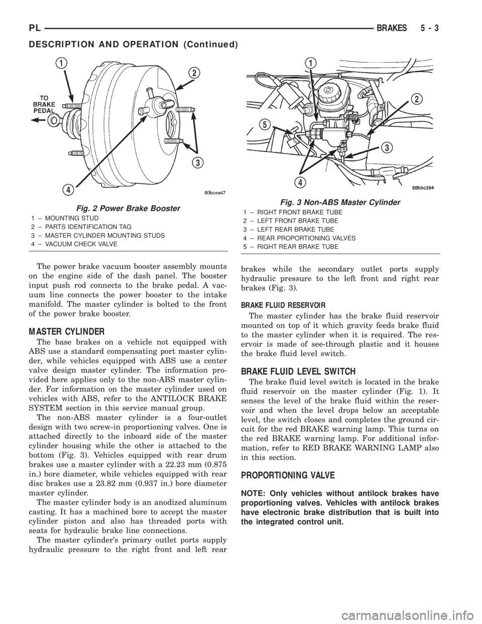
The power brake vacuum booster assembly mounts
on the engine side of the dash panel. The booster
input push rod connects to the brake pedal. A vac-
uum line connects the power booster to the intake
manifold. The master cylinder is bolted to the front
of the power brake booster.
MASTER CYLINDER
The base brakes on a vehicle not equipped with
ABS use a standard compensating port master cylin-
der, while vehicles equipped with ABS use a center
valve design master cylinder. The information pro-
vided here applies only to the non-ABS master cylin-
der. For information on the master cylinder used on
vehicles with ABS, refer to the ANTILOCK BRAKE
SYSTEM section in this service manual group.
The non-ABS master cylinder is a four-outlet
design with two screw-in proportioning valves. One is
attached directly to the inboard side of the master
cylinder housing while the other is attached to the
bottom (Fig. 3). Vehicles equipped with rear drum
brakes use a master cylinder with a 22.23 mm (0.875
in.) bore diameter, while vehicles equipped with rear
disc brakes use a 23.82 mm (0.937 in.) bore diameter
master cylinder.
The master cylinder body is an anodized aluminum
casting. It has a machined bore to accept the master
cylinder piston and also has threaded ports with
seats for hydraulic brake line connections.
The master cylinder's primary outlet ports supply
hydraulic pressure to the right front and left rearbrakes while the secondary outlet ports supply
hydraulic pressure to the left front and right rear
brakes (Fig. 3).
BRAKE FLUID RESERVOIR
The master cylinder has the brake fluid reservoir
mounted on top of it which gravity feeds brake fluid
to the master cylinder when it is required. The res-
ervoir is made of see-through plastic and it houses
the brake fluid level switch.
BRAKE FLUID LEVEL SWITCH
The brake fluid level switch is located in the brake
fluid reservoir on the master cylinder (Fig. 1). It
senses the level of the brake fluid within the reser-
voir and when the level drops below an acceptable
level, the switch closes and completes the ground cir-
cuit for the red BRAKE warning lamp. This turns on
the red BRAKE warning lamp. For additional infor-
mation, refer to RED BRAKE WARNING LAMP also
in this section.
PROPORTIONING VALVE
NOTE: Only vehicles without antilock brakes have
proportioning valves. Vehicles with antilock brakes
have electronic brake distribution that is built into
the integrated control unit.
Fig. 2 Power Brake Booster
1 ± MOUNTING STUD
2 ± PARTS IDENTIFICATION TAG
3 ± MASTER CYLINDER MOUNTING STUDS
4 ± VACUUM CHECK VALVE
Fig. 3 Non-ABS Master Cylinder
1 ± RIGHT FRONT BRAKE TUBE
2 ± LEFT FRONT BRAKE TUBE
3 ± LEFT REAR BRAKE TUBE
4 ± REAR PROPORTIONING VALVES
5 ± RIGHT REAR BRAKE TUBE
PLBRAKES 5 - 3
DESCRIPTION AND OPERATION (Continued)
Page 168 of 1285
SERVICE DIAGNOSISÐCLUTCH GRAB/CHATTER
CONDITION POSSIBLE CAUSES CORRECTION
CLUTCH DISC
FACING COVERED
WITH OIL OR
GREASEOil leak at engine rear main or transaxle
input shaft sealCorrect leak and replace modular clutch
assembly
Too much grease applied to splines of disc
and input shaftApply lighter coating of grease to splines
NO FAULT FOUND
WITH CLUTCH
COMPONENTSProblem actually related to suspension or
driveline componentFurther diagnosis required. Check
engine/transmission mounts, suspension
attaching parts and other driveline
components as needed.
Engine related problems Check EFI and ignition systems
PARTIAL
ENGAGEMENT OF
CLUTCH DISCClutch cover, spring, or release fingers
bent, distorted (rough handling, improper
assembly)Replace modular clutch assembly
Clutch disc damaged or distorted Replace modular clutch assembly
Clutch misalignment Check alignment and runout of flywheel,
disc, or cover. Check clutch housing to
engine dowels and dowel holes for damage.
Correct as necessary.
SERVICE DIAGNOSISÐCLUTCH SLIPS
CONDITION POSSIBLE CAUSES CORRECTION
DISC FACING
WORN OUTNormal wear. Replace modular clutch assembly.
Driver frequently rides (slips) clutch, results
in rapid wear overheating.Replace modular clutch assembly
Insufficient clutch cover diaphragm spring
tensionReplace modular clutch assembly
CLUTCH DISC
FACING
CONTAMINATED
WITH OIL OR
GREASELeak at rear main oil seal or transaxle input
shaft sealReplace leaking seals. Replace modular
clutch assembly.
Excessive amount of grease applied to
input shaft splinesApply less grease to input shaft. Replace
modular clutch assembly
Road splash, water entering housing Seal housing. Inspect clutch assembly.
CLUTCH IS
RUNNING
PARTIALLY
DISENGAGEDRelease bearing sticking or binding, does
not return to normal running position.Verify that bearing is actually binding. Then,
replace bearing and transmission front
bearing retainer if sleeve surface is
damaged.
Cable self-adjuster mechanism sticking or
binding causing high preloadVerify that self-adjuster is free to move
PLCLUTCH 6 - 3
DIAGNOSIS AND TESTING (Continued)
Page 170 of 1285
DRIVE PLATE MISALIGNMENT
Common causes of misalignment are:
²Heat warping
²Mounting drive plate on a dirty crankshaft
flange
²Incorrect bolt tightening
²Improper seating on the crankshaft shoulder
²Loose crankshaft bolts
Clean the crankshaft flange before mounting the
drive plate. Dirt and grease on the flange surface
may misalign the flywheel, causing excessive runout.
Use new bolts when mounting drive plate to crank-
shaft. Tighten drive plate bolts to specified torque
only. Over-tightening can distort the drive plate hub
causing excessive runout.
CLUTCH CHATTER COMPLAINTS
For all clutch chatter complaints, do the following:
(1) Check for loose, misaligned, or broken engine
and transmission mounts. If present, they should be
corrected at this time. Test vehicle for chatter. If
chatter is gone, there is no need to go any further. If
chatter persists:
(2) Check to see if clutch cable routing is correct
and operates smoothly.
(3) Check for loose connections in drive train. Cor-
rect any problems and determine if clutch chatter
complaints have been satisfied. If not:
(4) Remove transaxle. See Group 21, Manual Tran-
saxle for procedure.
(5) Check to see if the release bearing is sticky or
binding. Replace bearing, if needed.
(6) Check linkage for excessive wear on the pivot
stud and fork fingers. Replace all worn parts.
(7) Check clutch assembly for contamination (dirt,
oil). Replace clutch assembly, if required.
(8) Check to see if the clutch disc hub splines are
damaged. Replace with new clutch assembly, if nec-
essary.
(9) Check input shaft splines for damage. Replace,
if necessary.
(10) Check for uneven wear on clutch fingers.
(11) Check for broken clutch cover diaphragm
spring fingers. Replace with new clutch assembly, if
necessary.
CLASH±INTO±REVERSE COMPLAINTS
Certain NV T350 (A-578) manual transaxles are
equipped with a reverse brake. It prevents clash
when shifting into reverse, but only if the vehicle is
not moving. See Group 21, Transaxle for further
diagnosis.
(1) Depress clutch pedal to floor and hold. After
three seconds, shift to reverse. If clash is present,
clutch has excessive spin time, and the reverse brake
may not be functioning.(2) Remove transaxle. See Group 21, Manual Tran-
saxle for procedure.
(3) Check the input shaft spline, clutch disc
splines, and release bearing for dry rust. If present,
clean rust off and apply a light coat of bearing grease
to the input shaft splines. Apply grease on the input
shaft splines only where the clutch disc slides. Verify
that the clutch disc slides freely along the input shaft
spline.
(4) Check to see if the clutch disc hub splines are
damaged, and replace with new clutch assembly if
required.
(5) Check the input shaft for damaged splines.
Replace as necessary.
(6) Check for broken clutch cover diaphragm
spring fingers.
(7) Install clutch assembly and transaxle.
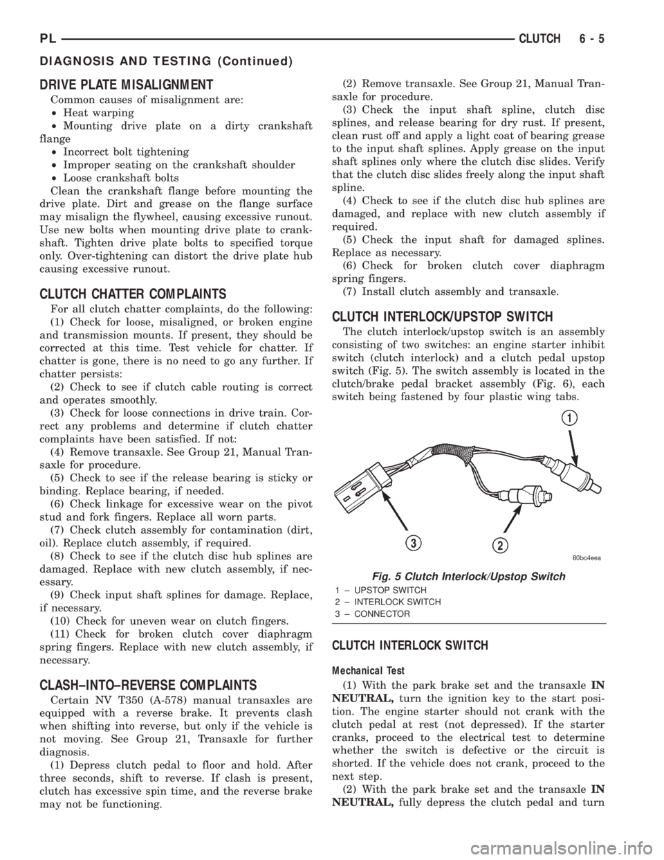
CLUTCH INTERLOCK/UPSTOP SWITCH
The clutch interlock/upstop switch is an assembly
consisting of two switches: an engine starter inhibit
switch (clutch interlock) and a clutch pedal upstop
switch (Fig. 5). The switch assembly is located in the
clutch/brake pedal bracket assembly (Fig. 6), each
switch being fastened by four plastic wing tabs.
CLUTCH INTERLOCK SWITCH
Mechanical Test
(1) With the park brake set and the transaxleIN
NEUTRAL,turn the ignition key to the start posi-
tion. The engine starter should not crank with the
clutch pedal at rest (not depressed). If the starter
cranks, proceed to the electrical test to determine
whether the switch is defective or the circuit is
shorted. If the vehicle does not crank, proceed to the
next step.
(2) With the park brake set and the transaxleIN
NEUTRAL,fully depress the clutch pedal and turn
Fig. 5 Clutch Interlock/Upstop Switch
1 ± UPSTOP SWITCH
2 ± INTERLOCK SWITCH
3 ± CONNECTOR
PLCLUTCH 6 - 5
DIAGNOSIS AND TESTING (Continued)
Page 182 of 1285
protection. MopartAntifreeze or the equivalent is
recommended for best engine cooling without corro-
sion. When mixed only to a freeze point of -37ÉC
(-35ÉF) to -59ÉC (-50ÉF). If it looses color or becomes
contaminated, drain, flush, and replace with fresh
properly mixed solution.
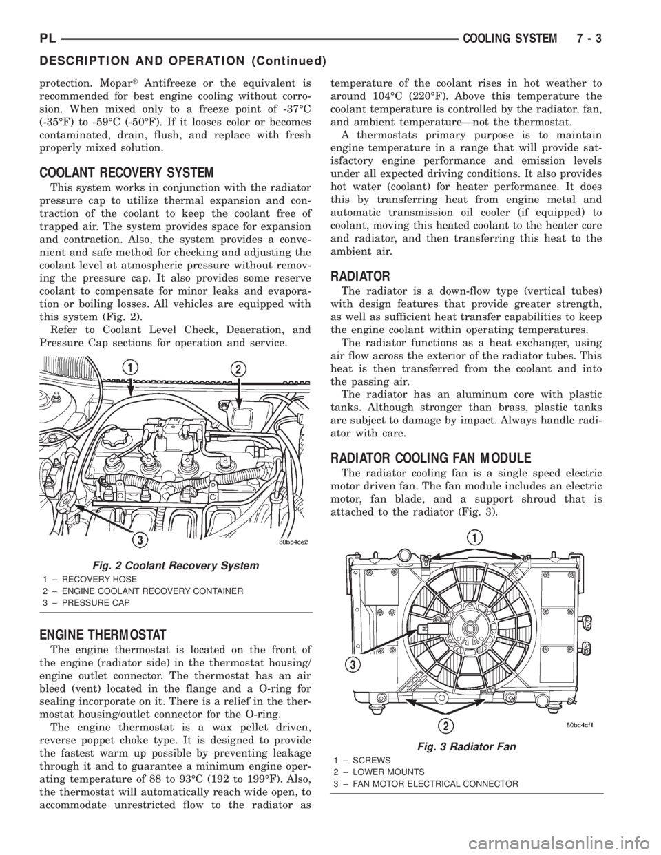
COOLANT RECOVERY SYSTEM
This system works in conjunction with the radiator
pressure cap to utilize thermal expansion and con-
traction of the coolant to keep the coolant free of
trapped air. The system provides space for expansion
and contraction. Also, the system provides a conve-
nient and safe method for checking and adjusting the
coolant level at atmospheric pressure without remov-
ing the pressure cap. It also provides some reserve
coolant to compensate for minor leaks and evapora-
tion or boiling losses. All vehicles are equipped with
this system (Fig. 2).
Refer to Coolant Level Check, Deaeration, and
Pressure Cap sections for operation and service.
ENGINE THERMOSTAT
The engine thermostat is located on the front of
the engine (radiator side) in the thermostat housing/
engine outlet connector. The thermostat has an air
bleed (vent) located in the flange and a O-ring for
sealing incorporate on it. There is a relief in the ther-
mostat housing/outlet connector for the O-ring.
The engine thermostat is a wax pellet driven,
reverse poppet choke type. It is designed to provide
the fastest warm up possible by preventing leakage
through it and to guarantee a minimum engine oper-
ating temperature of 88 to 93ÉC (192 to 199ÉF). Also,
the thermostat will automatically reach wide open, to
accommodate unrestricted flow to the radiator astemperature of the coolant rises in hot weather to
around 104ÉC (220ÉF). Above this temperature the
coolant temperature is controlled by the radiator, fan,
and ambient temperatureÐnot the thermostat.
A thermostats primary purpose is to maintain
engine temperature in a range that will provide sat-
isfactory engine performance and emission levels
under all expected driving conditions. It also provides
hot water (coolant) for heater performance. It does
this by transferring heat from engine metal and
automatic transmission oil cooler (if equipped) to
coolant, moving this heated coolant to the heater core
and radiator, and then transferring this heat to the
ambient air.
RADIATOR
The radiator is a down-flow type (vertical tubes)
with design features that provide greater strength,
as well as sufficient heat transfer capabilities to keep
the engine coolant within operating temperatures.
The radiator functions as a heat exchanger, using
air flow across the exterior of the radiator tubes. This
heat is then transferred from the coolant and into
the passing air.
The radiator has an aluminum core with plastic
tanks. Although stronger than brass, plastic tanks
are subject to damage by impact. Always handle radi-
ator with care.
RADIATOR COOLING FAN MODULE
The radiator cooling fan is a single speed electric
motor driven fan. The fan module includes an electric
motor, fan blade, and a support shroud that is
attached to the radiator (Fig. 3).
Fig. 2 Coolant Recovery System
1 ± RECOVERY HOSE
2 ± ENGINE COOLANT RECOVERY CONTAINER
3 ± PRESSURE CAP
Fig. 3 Radiator Fan
1 ± SCREWS
2 ± LOWER MOUNTS
3 ± FAN MOTOR ELECTRICAL CONNECTOR
PLCOOLING SYSTEM 7 - 3
DESCRIPTION AND OPERATION (Continued)
Page 200 of 1285
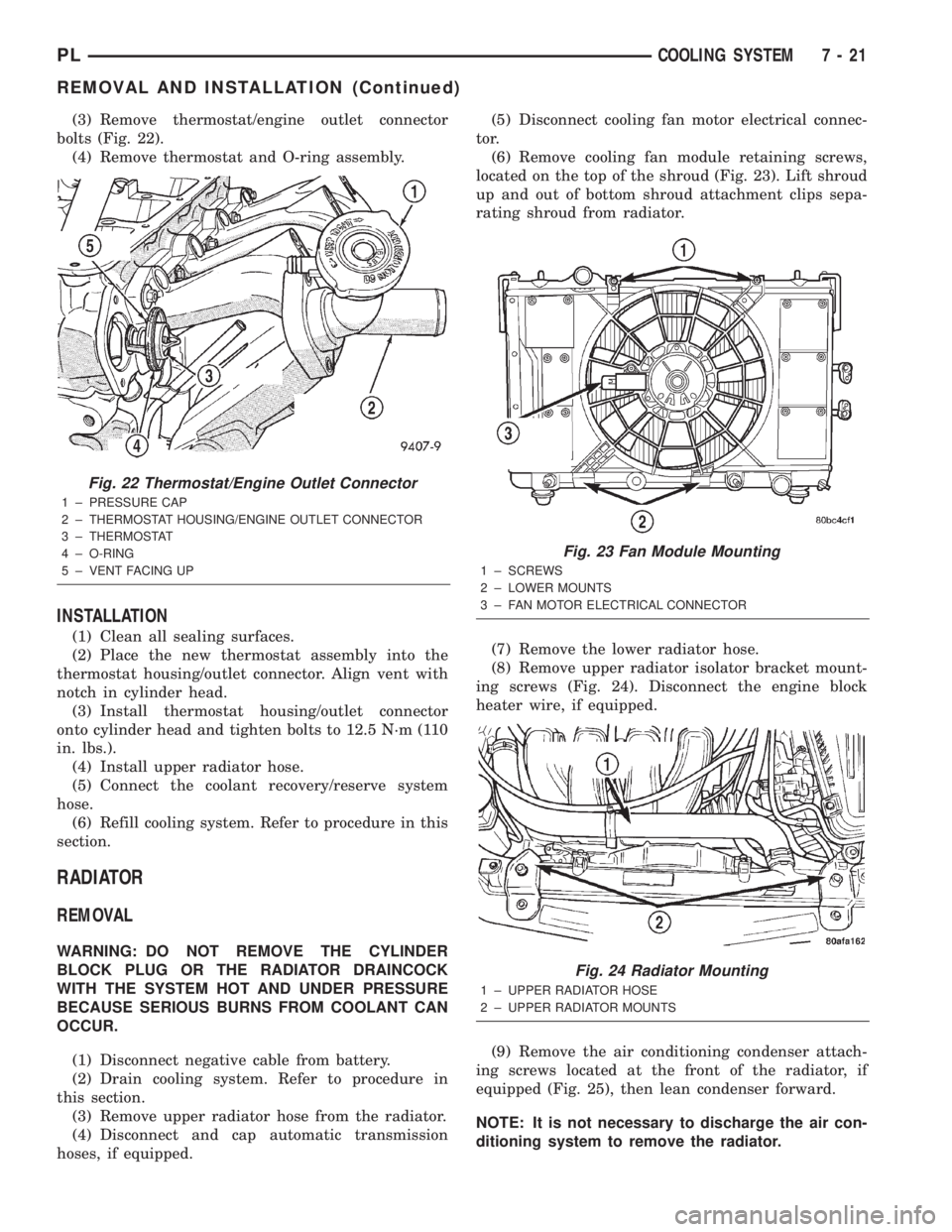
(3) Remove thermostat/engine outlet connector
bolts (Fig. 22).
(4) Remove thermostat and O-ring assembly.
INSTALLATION
(1) Clean all sealing surfaces.
(2) Place the new thermostat assembly into the
thermostat housing/outlet connector. Align vent with
notch in cylinder head.
(3) Install thermostat housing/outlet connector
onto cylinder head and tighten bolts to 12.5 N´m (110
in. lbs.).
(4) Install upper radiator hose.
(5) Connect the coolant recovery/reserve system
hose.
(6) Refill cooling system. Refer to procedure in this
section.
RADIATOR
REMOVAL
WARNING: DO NOT REMOVE THE CYLINDER
BLOCK PLUG OR THE RADIATOR DRAINCOCK
WITH THE SYSTEM HOT AND UNDER PRESSURE
BECAUSE SERIOUS BURNS FROM COOLANT CAN
OCCUR.
(1) Disconnect negative cable from battery.
(2) Drain cooling system. Refer to procedure in
this section.
(3) Remove upper radiator hose from the radiator.
(4) Disconnect and cap automatic transmission
hoses, if equipped.(5) Disconnect cooling fan motor electrical connec-
tor.
(6) Remove cooling fan module retaining screws,
located on the top of the shroud (Fig. 23). Lift shroud
up and out of bottom shroud attachment clips sepa-
rating shroud from radiator.
(7) Remove the lower radiator hose.
(8) Remove upper radiator isolator bracket mount-
ing screws (Fig. 24). Disconnect the engine block
heater wire, if equipped.
(9) Remove the air conditioning condenser attach-
ing screws located at the front of the radiator, if
equipped (Fig. 25), then lean condenser forward.
NOTE: It is not necessary to discharge the air con-
ditioning system to remove the radiator.
Fig. 22 Thermostat/Engine Outlet Connector
1 ± PRESSURE CAP
2 ± THERMOSTAT HOUSING/ENGINE OUTLET CONNECTOR
3 ± THERMOSTAT
4 ± O-RING
5 ± VENT FACING UP
Fig. 23 Fan Module Mounting
1 ± SCREWS
2 ± LOWER MOUNTS
3 ± FAN MOTOR ELECTRICAL CONNECTOR
Fig. 24 Radiator Mounting
1 ± UPPER RADIATOR HOSE
2 ± UPPER RADIATOR MOUNTS
PLCOOLING SYSTEM 7 - 21
REMOVAL AND INSTALLATION (Continued)
Page 201 of 1285
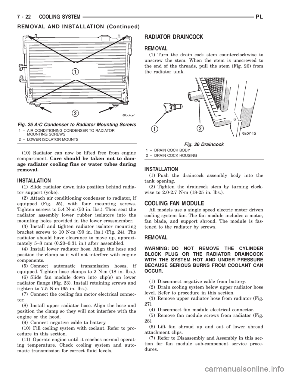
(10) Radiator can now be lifted free from engine
compartment.Care should be taken not to dam-
age radiator cooling fins or water tubes during
removal.
INSTALLATION
(1) Slide radiator down into position behind radia-
tor support (yoke).
(2) Attach air conditioning condenser to radiator, if
equipped (Fig. 25), with four mounting screws.
Tighten screws to 5.4 N´m (50 in. lbs.). Then seat the
radiator assembly lower rubber isolators into the
mounting holes provided in the lower crossmember.
(3) Install and tighten radiator isolator mounting
bracket screws to 10 N´m (90 in. lbs.) (Fig. 24). The
radiator should have clearance to move up, approxi-
mately 5±8 mm (0.20±0.31 in.) after assembled.
(4) Install lower radiator hose. Align the hose and
position the clamp so it will not interfere with engine
components.
(5) Connect automatic transmission hoses, if
equipped. Tighten hose clamps to 2 N´m (18 in. lbs.).
(6) Slide fan module down into clip(s) on lower
radiator flange (Fig. 23). Install retaining screws and
tighten to 7.5 N´m (65 in. lbs.).
(7) Connect the cooling fan motor electrical connec-
tor.
(8) Install upper radiator hose. Align the hose and
position the clamp so they will not interfere with the
engine or the hood.
(9) Connect negative cable to battery.
(10) Fill cooling system with coolant. Refer to pro-
cedure in this section.
(11) Operate engine until it reaches normal operat-
ing temperature. Check cooling system and auto-
matic transmission for correct fluid levels.
RADIATOR DRAINCOCK
REMOVAL
(1) Turn the drain cock stem counterclockwise to
unscrew the stem. When the stem is unscrewed to
the end of the threads, pull the stem (Fig. 26) from
the radiator tank.
INSTALLATION
(1) Push the draincock assembly body into the
tank opening.
(2) Tighten the draincock stem by turning clock-
wise to 2.0-2.7 N´m (18-25 in. lbs.).
COOLING FAN MODULE
All models use a single speed electric motor driven
cooling system fan. The fan module includes a motor,
fan blade, and support shroud. The module is fas-
tened to the radiator by screws.
REMOVAL
WARNING: DO NOT REMOVE THE CYLINDER
BLOCK PLUG OR THE RADIATOR DRAINCOCK
WITH THE SYSTEM HOT AND UNDER PRESSURE
BECAUSE SERIOUS BURNS FROM COOLANT CAN
OCCUR.
(1) Disconnect negative cable from battery.
(2) Drain cooling system below upper radiator hose
level. Refer to procedure in this section.
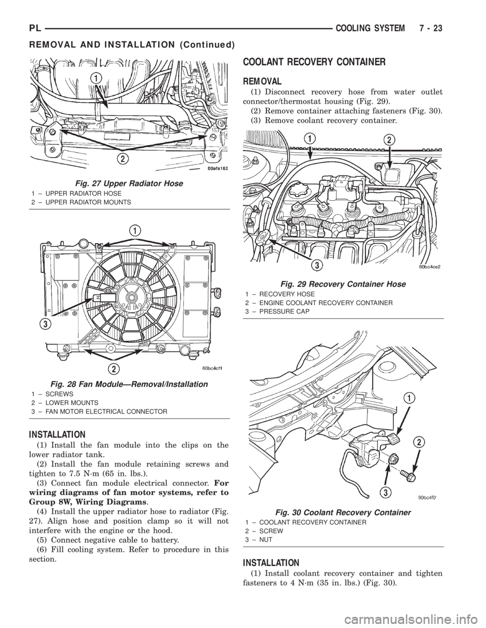
(3) Remove upper radiator hose from radiator (Fig.
27).
(4) Disconnect fan module electrical connector.
(5) Remove fan module screws from radiator (Fig.
28).
(6) Lift fan shroud up and out of lower shroud
attachment clips.
(7) Refer to Disassembly and Assembly in this sec-
tion for fan module sub-component service proce-
dures.
Fig. 25 A/C Condenser to Radiator Mounting Screws
1 ± AIR CONDITIONING CONDENSER TO RADIATOR
MOUNTING SCREWS
2 ± LOWER ISOLATOR MOUNTS
Fig. 26 Draincock
1 ± DRAIN COCK BODY
2 ± DRAIN COCK HOUSING
7 - 22 COOLING SYSTEMPL
REMOVAL AND INSTALLATION (Continued)
Page 202 of 1285
INSTALLATION
(1) Install the fan module into the clips on the
lower radiator tank.
(2) Install the fan module retaining screws and
tighten to 7.5 N´m (65 in. lbs.).
(3) Connect fan module electrical connector.For
wiring diagrams of fan motor systems, refer to
Group 8W, Wiring Diagrams.
(4) Install the upper radiator hose to radiator (Fig.
27). Align hose and position clamp so it will not
interfere with the engine or the hood.
(5) Connect negative cable to battery.
(6) Fill cooling system. Refer to procedure in this
section.
COOLANT RECOVERY CONTAINER
REMOVAL
(1) Disconnect recovery hose from water outlet
connector/thermostat housing (Fig. 29).
(2) Remove container attaching fasteners (Fig. 30).
(3) Remove coolant recovery container.
INSTALLATION
(1) Install coolant recovery container and tighten
fasteners to 4 N´m (35 in. lbs.) (Fig. 30).
Fig. 27 Upper Radiator Hose
1 ± UPPER RADIATOR HOSE
2 ± UPPER RADIATOR MOUNTS
Fig. 28 Fan ModuleÐRemoval/Installation
1 ± SCREWS
2 ± LOWER MOUNTS
3 ± FAN MOTOR ELECTRICAL CONNECTOR
Fig. 29 Recovery Container Hose
1 ± RECOVERY HOSE
2 ± ENGINE COOLANT RECOVERY CONTAINER
3 ± PRESSURE CAP
Fig. 30 Coolant Recovery Container
1 ± COOLANT RECOVERY CONTAINER
2 ± SCREW
3 ± NUT
PLCOOLING SYSTEM 7 - 23
REMOVAL AND INSTALLATION (Continued)
Page 238 of 1285
OPERATION
The Automatic Shutdown (ASD) relay supplies bat-
tery voltage to the fuel injectors, electronic ignition
coil and the heating elements in the oxygen sensors.
A buss bar in the Power Distribution Center (PDC)
supplies voltage to the solenoid side and contact side
of the relay. The fuse also protects the power circuit
for the fuel pump relay and pump. The fuse is
located in the PDC. Refer to the Wiring Diagrams for
circuit information.
The PCM controls the ASD relay by switching the
ground path for the solenoid side of the relay on and
off. The PCM turns the ground path off when the
ignition switch is in the Off position. When the igni-
tion switch is in On or Start, the PCM monitors the
crankshaft and camshaft position sensor signals to
determine engine speed and ignition timing (coil
dwell). If the PCM does not receive crankshaft and
camshaft position sensor signals when the ignition
switch is in the Run position, it will de-energize the
ASD relay.
CRANKSHAFT POSITION SENSORÐPCM
INPUT
DESCRIPTION
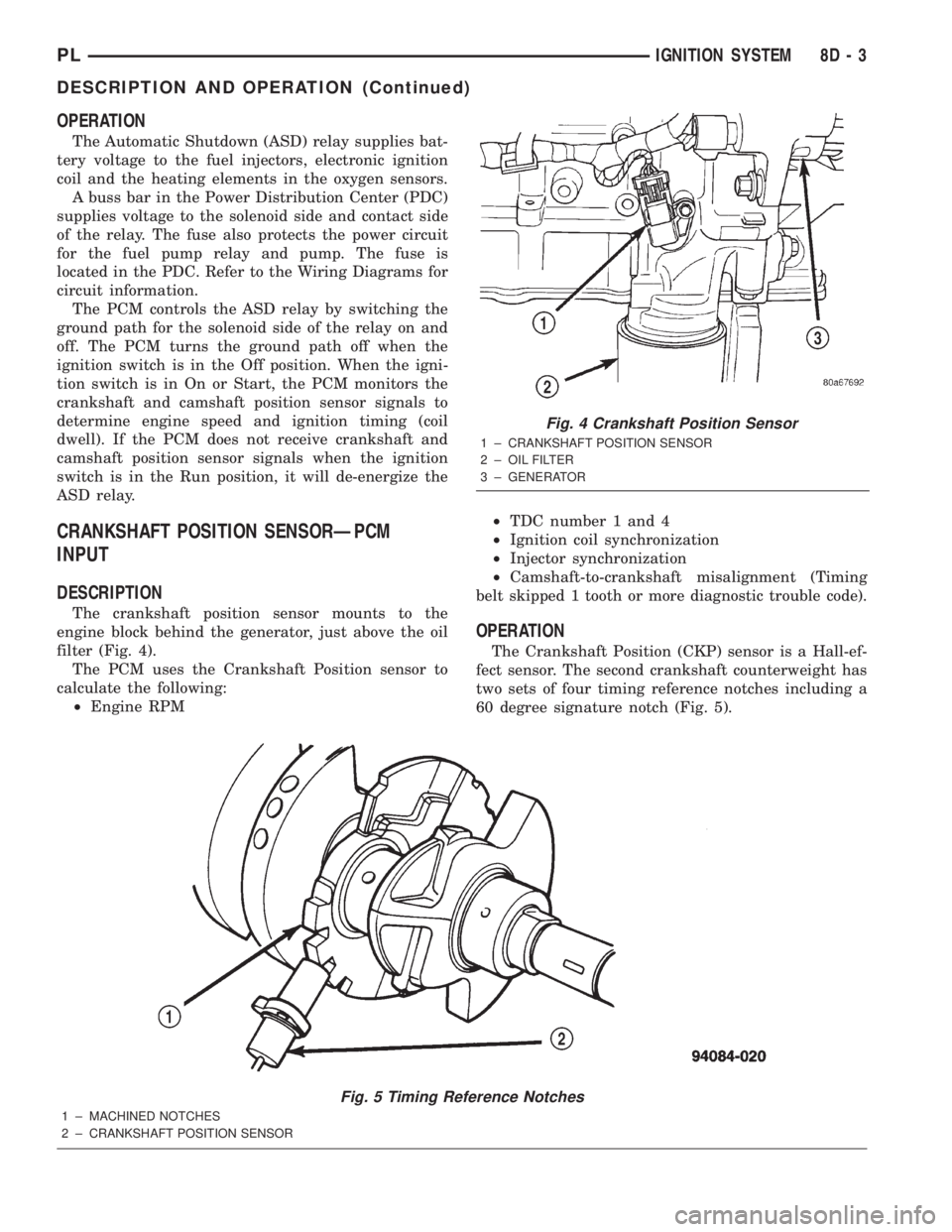
The crankshaft position sensor mounts to the
engine block behind the generator, just above the oil
filter (Fig. 4).
The PCM uses the Crankshaft Position sensor to
calculate the following:
²Engine RPM²TDC number 1 and 4
²Ignition coil synchronization
²Injector synchronization
²Camshaft-to-crankshaft misalignment (Timing
belt skipped 1 tooth or more diagnostic trouble code).
OPERATION
The Crankshaft Position (CKP) sensor is a Hall-ef-
fect sensor. The second crankshaft counterweight has
two sets of four timing reference notches including a
60 degree signature notch (Fig. 5).
Fig. 5 Timing Reference Notches
1 ± MACHINED NOTCHES
2 ± CRANKSHAFT POSITION SENSOR
Fig. 4 Crankshaft Position Sensor
1 ± CRANKSHAFT POSITION SENSOR
2 ± OIL FILTER
3 ± GENERATOR
PLIGNITION SYSTEM 8D - 3
DESCRIPTION AND OPERATION (Continued)