2000 DODGE NEON refrigerant type
[x] Cancel search: refrigerant typePage 1233 of 1285
GENERAL INFORMATION
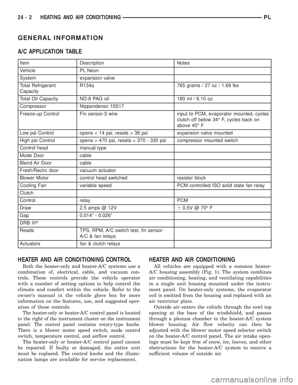
A/C APPLICATION TABLE
Item Description Notes
Vehicle PL Neon
System expansion valve
Total Refrigerant
CapacityR134a 765 grams / 27 oz / 1.69 lbs
Total Oil Capacity ND-8 PAG oil 180 ml / 6.10 oz
Compressor Nippondenso 10S17
Freeze-up Control Fin sensor-3 wire input to PCM, evaporator mounted, cycles
clutch off below 34É F, cycles back on
above 45É F
Low psi Control opens < 14 psi, resets > 38 psi expansion valve mounted
High psi Control opens > 470 psi, resets < 370 - 330 psi compressor mounted switch
Control head manual type
Mode Door cable
Blend Air Door cable
Fresh/Recirc door vacuum actuator
Blower Motor control head switched resistor block
Cooling Fan variable speed PCM controlled ISO solid state fan relay
Clutch
Control relay PCM
Draw 2.5 amps @ 12V60.5V @ 70É F
Gap 0.014º - 0.0269
DRB IIIT
Reads TPS, RPM, A/C switch test, fin sensor
A/C & fan relays
Actuators fan & clutch relays
HEATER AND AIR CONDITIONING CONTROL
Both the heater-only and heater-A/C systems use a
combination of, electrical, cable, and vacuum con-
trols. These controls provide the vehicle operator
with a number of setting options to help control the
climate and comfort within the vehicle. Refer to the
owner's manual in the vehicle glove box for more
information on the features, use, and suggested oper-
ation of these controls.
The heater-only or heater-A/C control panel is located
to the right of the instrument cluster on the instrument
panel. The control panel contains rotary-type knobs.
There is a blower motor speed switch, mode control
switch, temperature control, and airflow control.
The heater-only or heater-A/C control panel cannot
be repaired. If faulty or damaged, the entire unit
must be replaced. The control knobs and the illumi-
nation lamps are available for service replacement.
HEATER AND AIR CONDITIONING
All vehicles are equipped with a common heater-
A/C housing assembly (Fig. 1). The system combines
air conditioning, heating, and ventilating capabilities
in a single unit housing mounted under the instru-
ment panel. On heater-only systems, the evaporator
coil is omitted from the housing and replaced with an
air restrictor plate.
Outside air enters the vehicle through the cowl top
opening at the base of the windshield, and passes
through a plenum chamber to the heater-A/C system
blower housing. Air flow velocity can then be
adjusted with the blower motor speed selector switch
on the heater-A/C control panel. The air intake open-
ings must be kept free of snow, ice, leaves, and other
obstructions for the heater-A/C system to receive a
sufficient volume of outside air.
24 - 2 HEATING AND AIR CONDITIONINGPL
Page 1234 of 1285
It is also important to keep the air intake openings
clear of debris because leaf particles and other debris
that is small enough to pass through the cowl ple-
num screen can accumulate within the heater-A/C
housing. The closed, warm, damp and dark environ-
ment created within the heater-A/C housing is ideal
for the growth of certain molds, mildews and other
fungi. Any accumulation of decaying plant matter
provides an additional food source for fungal spores,
which enter the housing with the fresh air. Excess
debris, as well as objectionable odors created by
decaying plant matter and growing fungi can be dis-
charged into the passenger compartment during
heater-A/C system operation.
The heater and optional air conditioner are blend-
air type systems. In a blend-air system, a blend-air
door controls the amount of unconditioned air (or
cooled air from the evaporator on models with air
conditioning) that is allowed to flow through, or
around, the heater core. A temperature control knob
on the heater-A/C control panel determines the dis-
charge air temperature by moving a cable, which
operates the blend-air door. This allows an almost
immediate manual control of the output air tempera-
ture of the system.
The mode control knob on the heater-only or heat-
er-A/C control panel is used to direct the conditioned
air to the selected system outlets. The mode control
switch uses a cable to control the mode door, while
the recirculation air door is operated by a vacuum
actuator motor.On air conditioned vehicles, the outside air intake
can be shut off by selecting the recirculation mode
(Recirc) with the mode control knob. This will oper-
ate a vacuum actuated recirculating air door that
closes off the outside fresh air intake and recirculates
the air that is already inside the vehicle.
The optional air conditioner for all models is
designed for the use of non-CFC, R-134a refrigerant.
The air conditioning system has an evaporator to cool
and dehumidify the incoming air prior to blending it
with the heated air. This air conditioning system
uses an evaporator probe to maintain minimum
evaporator temperature and prevent evaporator
freezing, and cycles the compressor clutch.
INTRODUCTION
Both the heater and the heater/air conditioning
systems share many of the same functioning compo-
nents. This group will deal with both systems
together when component function is common, and
separately when they are not.
For proper operation of the instrument panel con-
trols, refer to the Owner's Manual provided with the
vehicle.
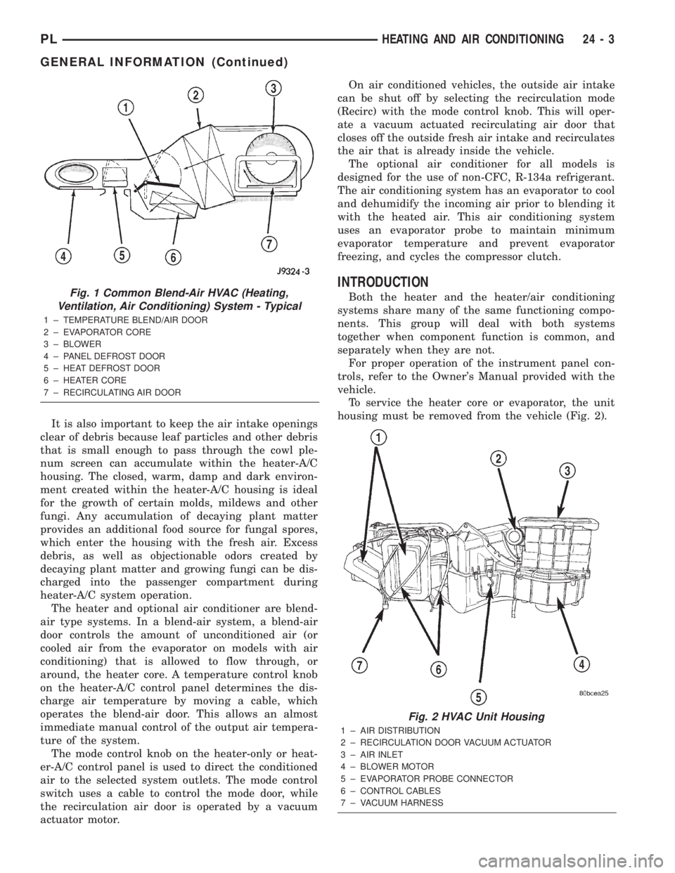
To service the heater core or evaporator, the unit
housing must be removed from the vehicle (Fig. 2).Fig. 1 Common Blend-Air HVAC (Heating,
Ventilation, Air Conditioning) System - Typical
1 ± TEMPERATURE BLEND/AIR DOOR
2 ± EVAPORATOR CORE
3 ± BLOWER
4 ± PANEL DEFROST DOOR
5 ± HEAT DEFROST DOOR
6 ± HEATER CORE
7 ± RECIRCULATING AIR DOOR
Fig. 2 HVAC Unit Housing
1 ± AIR DISTRIBUTION
2 ± RECIRCULATION DOOR VACUUM ACTUATOR
3 ± AIR INLET
4 ± BLOWER MOTOR
5 ± EVAPORATOR PROBE CONNECTOR
6 ± CONTROL CABLES
7 ± VACUUM HARNESS
PLHEATING AND AIR CONDITIONING 24 - 3
GENERAL INFORMATION (Continued)
Page 1235 of 1285
SAFETY PRECAUTIONS AND WARNINGS
WARNING: WEAR EYE PROTECTION WHEN SER-
VICING THE AIR CONDITIONING REFRIGERANT
SYSTEM. SERIOUS EYE INJURY CAN RESULT
FROM EYE CONTACT WITH REFRIGERANT. IF EYE
CONTACT IS MADE, SEEK MEDICAL ATTENTION
IMMEDIATELY.
DO NOT EXPOSE REFRIGERANT TO OPEN
FLAME. POISONOUS GAS IS CREATED WHEN
REFRIGERANT IS BURNED. AN ELECTRONIC TYPE
LEAK DETECTOR IS RECOMMENDED.
LARGE AMOUNTS OF REFRIGERANT RELEASED
IN A CLOSED WORK AREA WILL DISPLACE THE
OXYGEN AND CAUSE SUFFOCATION.
THE EVAPORATION RATE OF REFRIGERANT AT
AVERAGE TEMPERATURE AND ALTITUDE IS
EXTREMELY HIGH. AS A RESULT, ANYTHING THAT
COMES IN CONTACT WITH THE REFRIGERANT
WILL FREEZE. ALWAYS PROTECT SKIN OR DELI-
CATE OBJECTS FROM DIRECT CONTACT WITH
REFRIGERANT. R-134a SERVICE EQUIPMENT OR
VEHICLE A/C SYSTEM SHOULD NOT BE PRES-
SURE TESTED OR LEAK TESTED WITH COM-
PRESSED AIR.
SOME MIXTURES OF AIR and R-134a HAVE BEEN
SHOWN TO BE COMBUSTIBLE AT ELEVATED
PRESSURES. THESE MIXTURES ARE POTENTIALLY
DANGEROUS AND MAY RESULT IN FIRE OR
EXPLOSION CAUSING INJURY OR PROPERTY
DAMAGE.
ANTIFREEZE IS AN ETHYLENE GLYCOL BASE
COOLANT AND IS HARMFUL IF SWALLOWED OR
INHALED. SEEK MEDICAL ATTENTION IMMEDI-
ATELY IF SWALLOWED OR INHALED. DO NOT
STORE IN OPEN OR UNMARKED CONTAINERS.
WASH SKIN AND CLOTHING THOROUGHLY AFTER
COMING IN CONTACT WITH ETHYLENE GLYCOL.
KEEP OUT OF REACH OF CHILDREN AND PETS.
DO NOT OPEN A COOLING SYSTEM WHEN THE
ENGINE IS AT RUNNING TEMPERATURE. PER-
SONAL INJURY CAN RESULT.
CAUTION: The engine cooling system is designed
to develop internal pressure of 97 to 123 kPa (14 to
18 psi). Allow the vehicle to cool a minimum of 15
minutes before opening the cooling system. Refer
to Group 7, Cooling System.
DESCRIPTION AND OPERATION
A/C REFRIGERANT LINES
DISCHARGE LINE
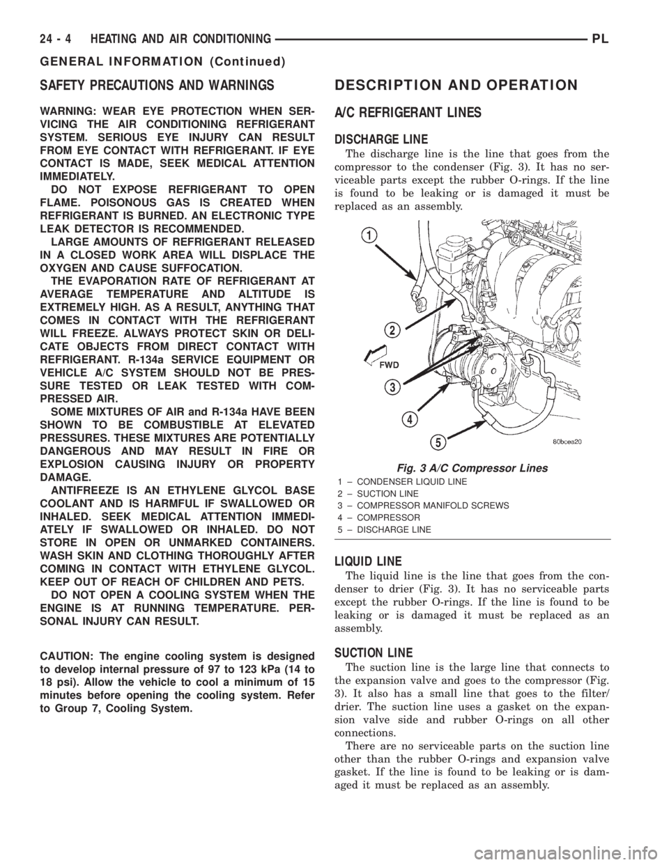
The discharge line is the line that goes from the
compressor to the condenser (Fig. 3). It has no ser-
viceable parts except the rubber O-rings. If the line
is found to be leaking or is damaged it must be
replaced as an assembly.
LIQUID LINE
The liquid line is the line that goes from the con-
denser to drier (Fig. 3). It has no serviceable parts
except the rubber O-rings. If the line is found to be
leaking or is damaged it must be replaced as an
assembly.
SUCTION LINE
The suction line is the large line that connects to
the expansion valve and goes to the compressor (Fig.
3). It also has a small line that goes to the filter/
drier. The suction line uses a gasket on the expan-
sion valve side and rubber O-rings on all other
connections.
There are no serviceable parts on the suction line
other than the rubber O-rings and expansion valve
gasket. If the line is found to be leaking or is dam-
aged it must be replaced as an assembly.
Fig. 3 A/C Compressor Lines
1 ± CONDENSER LIQUID LINE
2 ± SUCTION LINE
3 ± COMPRESSOR MANIFOLD SCREWS
4 ± COMPRESSOR
5 ± DISCHARGE LINE
24 - 4 HEATING AND AIR CONDITIONINGPL
GENERAL INFORMATION (Continued)
Page 1239 of 1285
NOTE: The oil used in the compressor is ND8 PAG
R-134a refrigerant oil. Only refrigerant oil of the
same type should be used to service the system.
Do not use any other oil. The oil container should
be kept tightly capped until it is ready for use.
Tightly cap afterwards to prevent contamination
from dirt and moisture. Refrigerant oil will quickly
absorb any moisture it comes in contact with. Spe-
cial effort must be used to keep all R-134a system
components moisture-free. Moisture in the oil is
very difficult to remove and will cause a reliability
problem with the compressor.
It will not be necessary to check oil level in the
compressor or to add oil unless there has been an oil
loss. Oil loss at a leak point will be evident by the
presence of a wet, shiny surface around the leak.
REFRIGERANT OIL LEVEL CHECK
When an air conditioning system is first assem-
bled, all components (except the compressor) are
refrigerant oil free. After the system has been
charged with R-134a refrigerant and operated, the oil
in the compressor is dispersed through the lines and
components. The evaporator, condenser, and filter-
drier will retain a significant amount of oil, refer to
the Refrigerant Oil Capacities chart. When a compo-
nent is replaced, the specified amount of refrigerant
oil must be added. When the compressor is replaced,
the amount of oil that is retained in the rest of the
system must be drained from the replacement com-
pressor. When a line or component has ruptured and
oil has escaped, the compressor should be removed
and drained. The filter-drier must be replaced along
with the ruptured part. The oil capacity of the sys-
tem, minus the amount of oil still in the remaining
components, can be measured and poured into the
suction port of the compressor.
VACUUM CONTROL SYSTEM
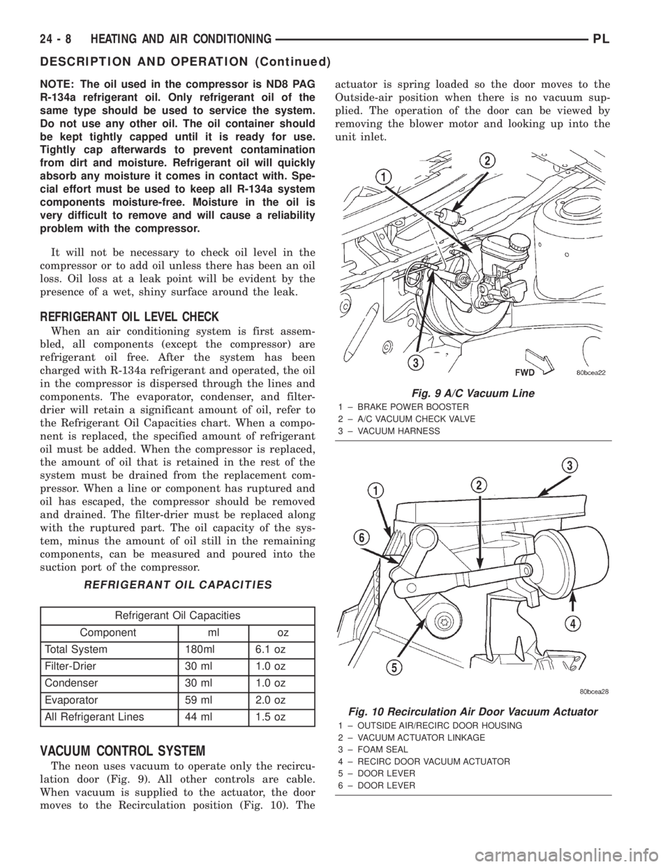
The neon uses vacuum to operate only the recircu-
lation door (Fig. 9). All other controls are cable.
When vacuum is supplied to the actuator, the door
moves to the Recirculation position (Fig. 10). Theactuator is spring loaded so the door moves to the
Outside-air position when there is no vacuum sup-
plied. The operation of the door can be viewed by
removing the blower motor and looking up into the
unit inlet.
REFRIGERANT OIL CAPACITIES
Refrigerant Oil Capacities
Component ml oz
Total System 180ml 6.1 oz
Filter-Drier 30 ml 1.0 oz
Condenser 30 ml 1.0 oz
Evaporator 59 ml 2.0 oz
All Refrigerant Lines 44 ml 1.5 oz
Fig. 9 A/C Vacuum Line
1 ± BRAKE POWER BOOSTER
2 ± A/C VACUUM CHECK VALVE
3 ± VACUUM HARNESS
Fig. 10 Recirculation Air Door Vacuum Actuator
1 ± OUTSIDE AIR/RECIRC DOOR HOUSING
2 ± VACUUM ACTUATOR LINKAGE
3 ± FOAM SEAL
4 ± RECIRC DOOR VACUUM ACTUATOR
5 ± DOOR LEVER
6 ± DOOR LEVER
24 - 8 HEATING AND AIR CONDITIONINGPL
DESCRIPTION AND OPERATION (Continued)
Page 1250 of 1285
Then allow the system to evacuate an additional 10
minutes.
(3) Close all valves. Turn off and disconnect the
vacuum pump.
(4) The refrigerant system is prepared to be
charged with refrigerant.
R-134a REFRIGERANT
This vehicle uses a refrigerant called R-134a. It is
a non-toxic, non-flammable, clear colorless liquefied
gas.
R-134a refrigerant is not compatible with R-12
refrigerant in an air conditioning system. Even a
small amount of R-12 in a R-134a system could cause
compressor failure, refrigerant oil to sludge and/or
poor performance.Never add any other type of
refrigerant to a system designed to use R-134a
refrigerant. System failure will occur.
The high pressure service port is located on the
ffilter/drier. The low pressure service port is located
on the suction line near the strut tower.
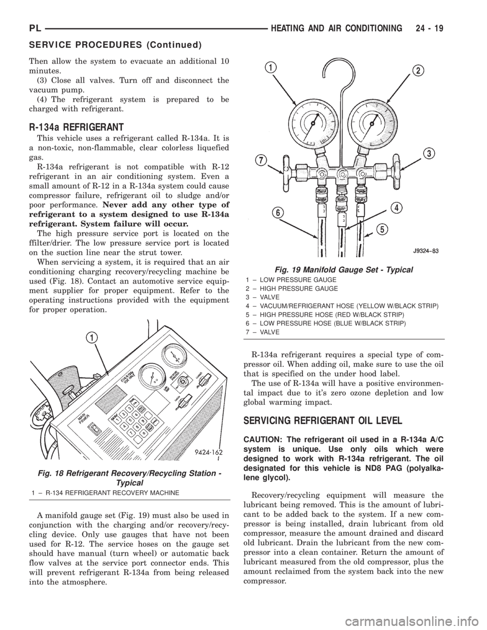
When servicing a system, it is required that an air
conditioning charging recovery/recycling machine be
used (Fig. 18). Contact an automotive service equip-
ment supplier for proper equipment. Refer to the
operating instructions provided with the equipment
for proper operation.
A manifold gauge set (Fig. 19) must also be used in
conjunction with the charging and/or recovery/recy-
cling device. Only use gauges that have not been
used for R-12. The service hoses on the gauge set
should have manual (turn wheel) or automatic back
flow valves at the service port connector ends. This
will prevent refrigerant R-134a from being released
into the atmosphere.R-134a refrigerant requires a special type of com-
pressor oil. When adding oil, make sure to use the oil
that is specified on the under hood label.
The use of R-134a will have a positive environmen-
tal impact due to it's zero ozone depletion and low
global warming impact.
SERVICING REFRIGERANT OIL LEVEL
CAUTION: The refrigerant oil used in a R-134a A/C
system is unique. Use only oils which were
designed to work with R-134a refrigerant. The oil
designated for this vehicle is ND8 PAG (polyalka-
lene glycol).
Recovery/recycling equipment will measure the
lubricant being removed. This is the amount of lubri-
cant to be added back to the system. If a new com-
pressor is being installed, drain lubricant from old
compressor, measure the amount drained and discard
old lubricant. Drain the lubricant from the new com-
pressor into a clean container. Return the amount of
lubricant measured from the old compressor, plus the
amount reclaimed from the system back into the new
compressor.
Fig. 18 Refrigerant Recovery/Recycling Station -
Typical
1 ± R-134 REFRIGERANT RECOVERY MACHINE
Fig. 19 Manifold Gauge Set - Typical
1 ± LOW PRESSURE GAUGE
2 ± HIGH PRESSURE GAUGE
3 ± VALVE
4 ± VACUUM/REFRIGERANT HOSE (YELLOW W/BLACK STRIP)
5 ± HIGH PRESSURE HOSE (RED W/BLACK STRIP)
6 ± LOW PRESSURE HOSE (BLUE W/BLACK STRIP)
7 ± VALVE
PLHEATING AND AIR CONDITIONING 24 - 19
SERVICE PROCEDURES (Continued)
Page 1251 of 1285
(1) Discharge refrigerant system using recovery/re-
cycling equipment if charge is present.
(2) Disconnect refrigerant lines from A/C compres-
sor. Cap the open lines to prevent moisture from
entering system.
(3) Remove compressor from vehicle.
(4) From suction port on top of compressor, drain
lubricant from compressor.
(5) Add system capacity minus the capacity of
components that have not been replaced. Refer to the
Lubricant Capacity Chart. Add lubricant through the
suction port on compressor. This is not to exceed 180
ml (6.10 oz.) in total.
(6) Install compressor and connect refrigerant
lines. Then evacuate and charge refrigerant system.
SYSTEM LEAK CHECKING
WARNING: R-134a SERVICE EQUIPMENT OR VEHI-
CLE A/C SYSTEM SHOULD NOT BE PRESSURE
TESTED OR LEAK TESTED WITH COMPRESSED
AIR. MIXTURE OF AIR and R-134a CAN BE COM-
BUSTIBLE AT ELEVATED PRESSURES. THESE MIX-
TURES ARE POTENTIALLY DANGEROUS AND MAY
RESULT IN FIRE OR EXPLOSION CAUSING INJURY
OR PROPERTY DAMAGE.
AVOID BREATHING A/C REFRIGERANT AND
LUBRICANT VAPOR OR MIST. EXPOSURE MAY
IRRITATE EYES, NOSE AND THROAT. USE ONLY
APPROVED SERVICE EQUIPMENT MEETING SAE
REQUIREMENTS TO DISCHARGE R-134a SYSTEM.
IF ACCIDENTAL SYSTEM DISCHARGE OCCURS,
VENTILATE WORK AREA BEFORE RESUMING SER-
VICE.
If the A/C system is not cooling properly, determine
if the refrigerant system is fully charged with
R-134a. This is accomplished by performing a system
Charge Level-Check or Fill. If while performing this
test A/C liquid line pressure is less than 345 kPa (50
psi) proceed to Empty Refrigerant System Leak Test.
If liquid line pressure is greater than 345 kPa (50
psi) proceed to low refrigerant level leak test. If the
refrigerant system is empty or low in refrigerant
charge, a leak at any line fitting or component seal is
likely. A review of the fittings, lines and components
for oily residue is an indication of the leak location.
To detect a leak in the refrigerant system, perform
one of the following procedures as indicated by the
symptoms.
EMPTY REFRIGERANT SYSTEM LEAK TEST
(1) Evacuate the refrigerant system to the lowest
degree of vacuum possible (approx. 28 in Hg.). Deter-
mine if the system holds a vacuum for 15 minutes. If
vacuum is held, a leak is probably not present. If sys-tem will not maintain vacuum level, proceed with
this procedure.
(2) Prepare a.284 Kg. (10 oz.) refrigerant charge to
be injected into the system.
(3) Connect and dispense.284 Kg. (10 oz.) of refrig-
erant into the evacuated refrigerant system.
(4) Proceed to Step 2 of Low Refrigerant Level
Leak Test.
LOW REFRIGERANT LEVEL LEAK TEST
(1) Determine if there is any (R-134a) refrigerant
in the system.
(2) Position the vehicle in a wind free work area.
This will aid in detecting small leaks.
(3) Bring the refrigerant system up to operating
temperature and pressure. This is done by allowing
the engine to run for five minutes with the system
set to the following:
²Transaxle in Park
²Engine Idling at 700 rpm
²A/C Controls Set in 100 percent outside air
²Blower switch in the high A/C position
²A/C in the ON position
²Open all windows
CAUTION: A leak detector designed for R-12 refrig-
erant (only) will not detect leaks in a R-134a refrig-
erant system.
(4) Shut off the vehicle and wait 2 to 7 minutes.
Then use an Electronic Leak Detector that is
designed to detect R-134a type refrigerant and search
for leaks. Fittings, lines, or components that appear
to be oily usually indicates a refrigerant leak. To
inspect the evaporator core for leaks, insert the leak
detector probe into the drain tube opening or a heat
duct. A R-134a dye is available to aid in leak detec-
tion, use only Chrysler approved refrigerant dye.
If a thorough leak check has been completed with-
out indication of a leak, proceed to System Charge
Level.
REMOVAL AND INSTALLATION
A/C FILTER/DRIER
The filter/drier is mounted in a rubber grommet on
the right side of the engine compartment. The refrig-
erant must be recovered from the A/C system before
replacing the filter/drier assembly.
WARNING: THE REFRIGERATION SYSTEM MUST
BE COMPLETELY RECOVERED BEFORE PRO-
CEEDING WITH THIS OPERATION.
24 - 20 HEATING AND AIR CONDITIONINGPL
SERVICE PROCEDURES (Continued)
Page 1254 of 1285
(8) Remove compressor. If refrigerant lines were
not removed, lift compressor/clutch assembly and tie
it to a suitable component.
INSTALLATION
For installation, reverse the above procedures.
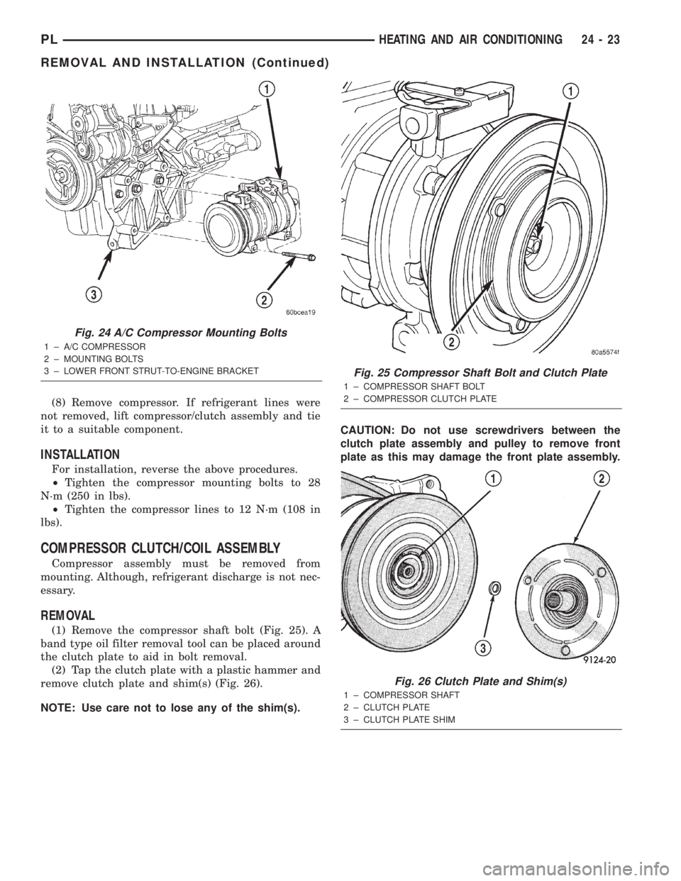
²Tighten the compressor mounting bolts to 28
N´m (250 in lbs).
²Tighten the compressor lines to 12 N´m (108 in
lbs).
COMPRESSOR CLUTCH/COIL ASSEMBLY
Compressor assembly must be removed from
mounting. Although, refrigerant discharge is not nec-
essary.
REMOVAL
(1) Remove the compressor shaft bolt (Fig. 25). A
band type oil filter removal tool can be placed around
the clutch plate to aid in bolt removal.
(2) Tap the clutch plate with a plastic hammer and
remove clutch plate and shim(s) (Fig. 26).
NOTE: Use care not to lose any of the shim(s).CAUTION: Do not use screwdrivers between the
clutch plate assembly and pulley to remove front
plate as this may damage the front plate assembly.
Fig. 24 A/C Compressor Mounting Bolts
1 ± A/C COMPRESSOR
2 ± MOUNTING BOLTS
3 ± LOWER FRONT STRUT-TO-ENGINE BRACKET
Fig. 25 Compressor Shaft Bolt and Clutch Plate
1 ± COMPRESSOR SHAFT BOLT
2 ± COMPRESSOR CLUTCH PLATE
Fig. 26 Clutch Plate and Shim(s)
1 ± COMPRESSOR SHAFT
2 ± CLUTCH PLATE
3 ± CLUTCH PLATE SHIM
PLHEATING AND AIR CONDITIONING 24 - 23
REMOVAL AND INSTALLATION (Continued)