2000 DODGE NEON transmission
[x] Cancel search: transmissionPage 4 of 1285
MAINTENANCE SCHEDULES
TABLE OF CONTENTS
page page
DESCRIPTION AND OPERATION
MAINTENANCE SCHEDULES................3
SPECIFICATIONS
UNSCHEDULED INSPECTION................3SCHEDULE ± A...........................3
SCHEDULE ± B...........................4
DESCRIPTION AND OPERATION
MAINTENANCE SCHEDULES
There are two maintenance schedules that show
proper service for your vehicle.
First is Schedule ±A. It lists all the scheduled
maintenance to be performed under ªnormalº operat-
ing conditions.
Second is Schedule ±B. It is a schedule for vehi-
cles that are operated under the following conditions:
²Frequent short trip driving less than 5 miles (8
km)
²Frequent driving in dusty conditions
²Extensive idling
²More than 50% of the driving is at sustained
high speeds during hot weather, above 90É F (32É C)
SPECIFICATIONS
UNSCHEDULED INSPECTION
At Each Stop For Fuel
²Check engine oil level and add as required.
²Check windshield washer solvent and add as
required.
Once A Month
²Check tire pressure and look for unusual wear
or damage.
²Inspect the battery and clean and tighten termi-
nals as required.
²Check fluid levels of coolant reservoir, brake
master cylinder, power steering and transmission.
Add fluid as required.
²Check all lights and all other electrical items for
correct operation.
At Each Oil Change
²Inspect the exhaust system.
²Inspect brake hoses.
²Inspect the CV joints and front suspension com-
ponent boots and seals.²Rotate the tires at each oil change interval
shown on Schedule ± A (7,500 miles - 12 000 km) or
every other interval on Schedule ± B (6,000 miles -
10 000 km).
²Check the engine coolant level, hoses, and
clamps.
If mileage is less than 7,500 miles (12 000 km)
yearly, replace the engine oil filter at each oil change.
EMISSION CONTROL SYSTEM MAINTENANCE
The scheduled emission maintenance listed inbold
typeon the Maintenance Schedules, must be done at
the mileage specified to assure the continued proper
functioning of the emission control system. These,
and all other maintenance services included in this
manual, should be done to provide the best vehicle
performance and reliability. More frequent mainte-
nance may be needed for vehicles in severe operating
conditions such as dusty areas and very short trip
driving.
FLUID FILL POINTS AND LUBRICATION
LOCATIONS
The fluid fill/check locations and lubrication loca-
tions are located in each applicable group.
SCHEDULE ± A
7,500 Miles (12 000 km) or at 6 months
²Change the engine oil.
²Replace the engine oil filter.
15,000 Miles (24 000 km) or at 12 months
²Change the engine oil.
²Replace the engine oil filter.
²Adjust the drive belt tension.
22,500 Miles (36 000 km) or at 18 months
²Change the engine oil.
²Replace the engine oil filter.
²Inspect the front brake pads and rear brake lin-
ings.
PLLUBRICATION AND MAINTENANCE 0 - 3
Page 8 of 1285

JUMP STARTING, TOWING, AND HOISTING
TABLE OF CONTENTS
page page
DESCRIPTION AND OPERATION
JUMP STARTING PROCEDURE...............7
TOWING RECOMMENDATIONS...............7
HOISTING RECOMMENDATIONS.............7SERVICE PROCEDURES
JUMP STARTING PROCEDURE...............7
TOWING RECOMMENDATIONS...............8
HOISTING RECOMMENDATIONS.............9
DESCRIPTION AND OPERATION
JUMP STARTING PROCEDURE
Describes the procedure for starting a disable vehi-
cle.
TOWING RECOMMENDATIONS
Describes the recommended towing procedures.
HOISTING RECOMMENDATIONS
Describes the location of hoisting and jacking
points so that the vehicle can be lifted by a floor jack
or hoist.
SERVICE PROCEDURES
JUMP STARTING PROCEDURE
WARNING: REVIEW ALL SAFETY PRECAUTIONS
AND WARNINGS IN GROUP 8A, BATTERY/START-
ING/CHARGING SYSTEMS DIAGNOSTICS. DO NOT
JUMP START A FROZEN BATTERY, PERSONAL
INJURY CAN RESULT. DO NOT JUMP START WHEN
MAINTENANCE FREE BATTERY INDICATOR DOT IS
YELLOW OR BRIGHT COLOR. DO NOT JUMP
START A VEHICLE WHEN THE BATTERY FLUID IS
BELOW THE TOP OF LEAD PLATES. DO NOT
ALLOW JUMPER CABLE CLAMPS TO TOUCH
EACH OTHER WHEN CONNECTED TO A BOOSTER
SOURCE. DO NOT USE OPEN FLAME NEAR BAT-
TERY. REMOVE METALLIC JEWELRY WORN ON
HANDS OR WRISTS TO AVOID INJURY BY ACCI-
DENTAL ARCING OF BATTERY CURRENT. WHEN
USING A HIGH OUTPUT BOOSTING DEVICE, DO
NOT ALLOW BATTERY VOLTAGE TO EXCEED 16
VOLTS. REFER TO INSTRUCTIONS PROVIDED
WITH DEVICE BEING USED.
CAUTION: When using another vehicle as a
booster, do not allow vehicles to touch. Electrical
systems can be damaged on either vehicle.
TO JUMP START A DISABLED VEHICLE:
(1) Raise hood on disabled vehicle and visually
inspect engine compartment for:
²Battery cable clamp condition, clean if necessary.
²Frozen battery.
²Yellow or bright color test indicator, if equipped.
²Low battery fluid level.
²Generator drive belt condition and tension.
²Fuel fumes or leakage, correct if necessary.
CAUTION: If the cause of starting problem on dis-
abled vehicle is severe, damage to booster vehicle
charging system can result.
(2) When using another vehicle as a booster
source, park the booster vehicle within cable reach.
Turn off all accessories, set the parking brake, place
the automatic transmission in PARK or the manual
transmission in NEUTRAL and turn the ignition
OFF.
(3) On disabled vehicle, place gear selector in park
or neutral and set park brake. Turn off all accesso-
ries.
(4) Connect jumper cables to booster battery. RED
clamp to positive terminal (+). BLACK clamp to neg-
ative terminal (-). DO NOT allow clamps at opposite
end of cables to touch, electrical arc will result.
Review all warnings in this procedure.
(5) On disabled vehicle, connect RED jumper cable
clamp to positive (+) terminal. Connect BLACK
jumper cable clamp to engine ground as close to the
ground cable attaching point as possible (Fig. 1).
(6) Start the engine in the vehicle which has the
booster battery, let the engine idle a few minutes,
then start the engine in the vehicle with the dis-
charged battery.
CAUTION: Do not crank starter motor on disabled
vehicle for more than 15 seconds, starter will over-
heat and could fail.
(7) Allow battery in disabled vehicle to charge to
at least 12.4 volts (75% charge) before attempting to
start engine. If engine does not start within 15 sec-
PLLUBRICATION AND MAINTENANCE 0 - 7
Page 62 of 1285
DIFFERENTIAL AND DRIVELINE
TABLE OF CONTENTS
page page
DESCRIPTION AND OPERATION
FRONT DRIVESHAFTS.....................1
DIAGNOSIS AND TESTING
DRIVESHAFT DIAGNOSIS...................2
REMOVAL AND INSTALLATION
DRIVESHAFTS...........................3
DISASSEMBLY AND ASSEMBLY
DRIVESHAFT RECONDITION................7INNER TRIPOD JOINT SEAL BOOT...........7
OUTER C/V JOINT SEAL BOOT.............13
SPECIFICATIONS
TORQUE...............................17
SPECIAL TOOLS
DRIVESHAFT............................17
DESCRIPTION AND OPERATION
FRONT DRIVESHAFTS
Vehicles equipped with either an automatic or
manual transmission use an unequal±length drive-
shaft system.The system incorporates two driveshaft assemblies
(left and right) that consist of an inner and outer
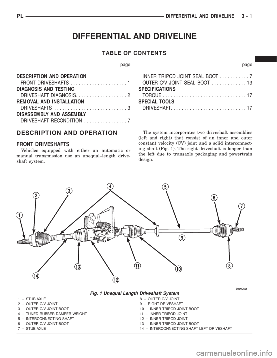
constant velocity (CV) joint and a solid interconnect-
ing shaft (Fig. 1). The right driveshaft is longer than
the left due to transaxle packaging and powertrain
design.
Fig. 1 Unequal Length Driveshaft System
1 ± STUB AXLE
2 ± OUTER C/V JOINT
3 ± OUTER C/V JOINT BOOT
4 ± TUNED RUBBER DAMPER WEIGHT
5 ± INTERCONNECTING SHAFT
6 ± OUTER C/V JOINT BOOT
7 ± STUB AXLE8 ± OUTER C/V JOINT
9 ± RIGHT DRIVESHAFT
10 ± INNER TRIPOD JOINT BOOT
11 ± INNER TRIPOD JOINT
12 ± INNER TRIPOD JOINT
13 ± INNER TRIPOD JOINT BOOT
14 ± INTERCONNECTING SHAFT LEFT DRIVESHAFT
PLDIFFERENTIAL AND DRIVELINE 3 - 1
Page 101 of 1285
BRAKE ROTOR LIMITS
Braking Rotor Rotor ThicknessMinimum
Rotor
ThicknessRotor
Thickness
VariationRotor Run
Out*Rotor Micro
Finish
Front Rotor21.87±22.13 mm
0.861-0.871 in.20.4 mm
0.803 in.0.013 mm
0.0005 in.0.08 mm
0.003 in.15-80 RMS
Rear Rotor8.75±9.25 mm
0.344 -0.364 in.7.25 mm
0.285 in.0.013 mm
0.0005 in.0.08 mm
0.003 in.15-80 RMS
* TIR Total Indicator Reading (Measured On Vehicle)
BRAKE DRUM MACHINING
If a brake drum is deeply scored or warped, it can
be machined on a brake lathe equipped to machine
brake drums. Follow the manufacturers instructions
on the machining procedure.
Measure the brake drum diameter before machin-
ing. If machining the drum will cause the drum to
exceed maximum allowable diameter, do not machine
the brake drum. It needs to be replaced.
CAUTION: Do not machine the brake drum if it will
cause the drum to exceed maximum allowable
diameter.
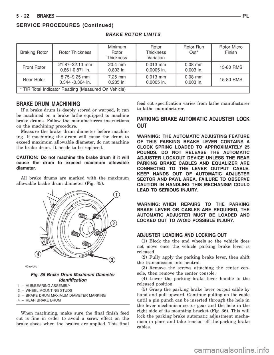
All brake drums are marked with the maximum
allowable brake drum diameter (Fig. 35).
When machining, make sure the final finish feed
cut is fine in order to avoid a screw effect on the
brake shoes when the brakes are applied. This finalfeed cut specification varies from lathe manufacturer
to lathe manufacturer.
PARKING BRAKE AUTOMATIC ADJUSTER LOCK
OUT
WARNING: THE AUTOMATIC ADJUSTING FEATURE
OF THIS PARKING BRAKE LEVER CONTAINS A
CLOCK SPRING LOADED TO APPROXIMATELY 25
POUNDS. DO NOT RELEASE THE AUTOMATIC
ADJUSTER LOCKOUT DEVICE UNLESS THE REAR
PARKING BRAKE CABLES AND EQUALIZER ARE
CONNECTED TO THE LEVER OUTPUT CABLE.
KEEP HANDS OUT OF AUTOMATIC ADJUSTER
SECTOR AND PAWL AREA. FAILURE TO OBSERVE
CAUTION IN HANDLING THIS MECHANISM COULD
LEAD TO SERIOUS INJURY.
WARNING: WHEN REPAIRS TO THE PARKING
BRAKE LEVER OR CABLES ARE REQUIRED, THE
AUTOMATIC ADJUSTER MUST BE LOADED AND
LOCKED OUT TO AVOID POSSIBLE INJURY.
ADJUSTER LOADING AND LOCKING OUT
(1) Block the tire and wheels so the vehicle does
not move once the vehicle parking brake lever is
released.
(2) Fully apply the parking brake lever, then shift
the transmission into neutral.
(3) Remove the screws attaching the center con-
sole, then remove the center console.
(4) Lower the parking brake lever handle to the
released position.
(5) Grasp the parking brake lever output cable by
hand and pull upward. Continue pulling on the cable
until a pin punch can be inserted through the hole in
the lever mechanism sector gear and the hole in the
right side of its mounting bracket (Fig. 36). This will
lock the parking brake automatic adjustment mecha-
nism in place and take tension off the parking brake
cables.
Fig. 35 Brake Drum Maximum Diameter
Identification
1 ± HUB/BEARING ASSEMBLY
2 ± WHEEL MOUNTING STUDS
3 ± BRAKE DRUM MAXIMUM DIAMETER MARKING
4 ± REAR BRAKE DRUM
5 - 22 BRAKESPL
SERVICE PROCEDURES (Continued)
Page 127 of 1285
PARKING BRAKE LEVER
WARNING: THE AUTOMATIC ADJUSTING FEATURE
OF THIS PARKING BRAKE LEVER CONTAINS A
CLOCK SPRING LOADED TO APPROXIMATELY 25
POUNDS. DO NOT RELEASE THE AUTOMATIC
ADJUSTER LOCKOUT DEVICE UNLESS THE REAR
PARKING BRAKE CABLES AND EQUALIZER ARE
CONNECTED TO THE LEVER OUTPUT CABLE.
KEEP HANDS OUT OF AUTOMATIC ADJUSTER
SECTOR AND PAWL AREA. FAILURE TO OBSERVE
CAUTION IN HANDLING THIS MECHANISM COULD
LEAD TO SERIOUS INJURY.
WARNING: WHEN REPAIRS TO THE PARKING
BRAKE LEVER OR CABLES ARE REQUIRED, THE
AUTOMATIC ADJUSTER MUST BE LOADED AND
LOCKED OUT TO AVOID POSSIBLE INJURY. THE
LEVER ADJUSTMENT MECHANISM CAN BE
LOADED AND LOCKED OUT AS OUTLINED IN THIS
PROCEDURE.
REMOVAL
(1) Block the tire and wheels so the vehicle does
not move once the vehicle parking brake lever is
released.
(2) Fully apply the parking brake lever, then shift
the transmission into neutral.
(3) Remove the screws attaching the center con-
sole, then remove the center console.
(4) Lower the parking brake lever handle to the
released position.
(5) Grasp the parking brake lever output cable by
hand and pull upward. Continue pulling on the cable
until a pin punch can be inserted through the hole in
the lever mechanism sector gear and the hole in the
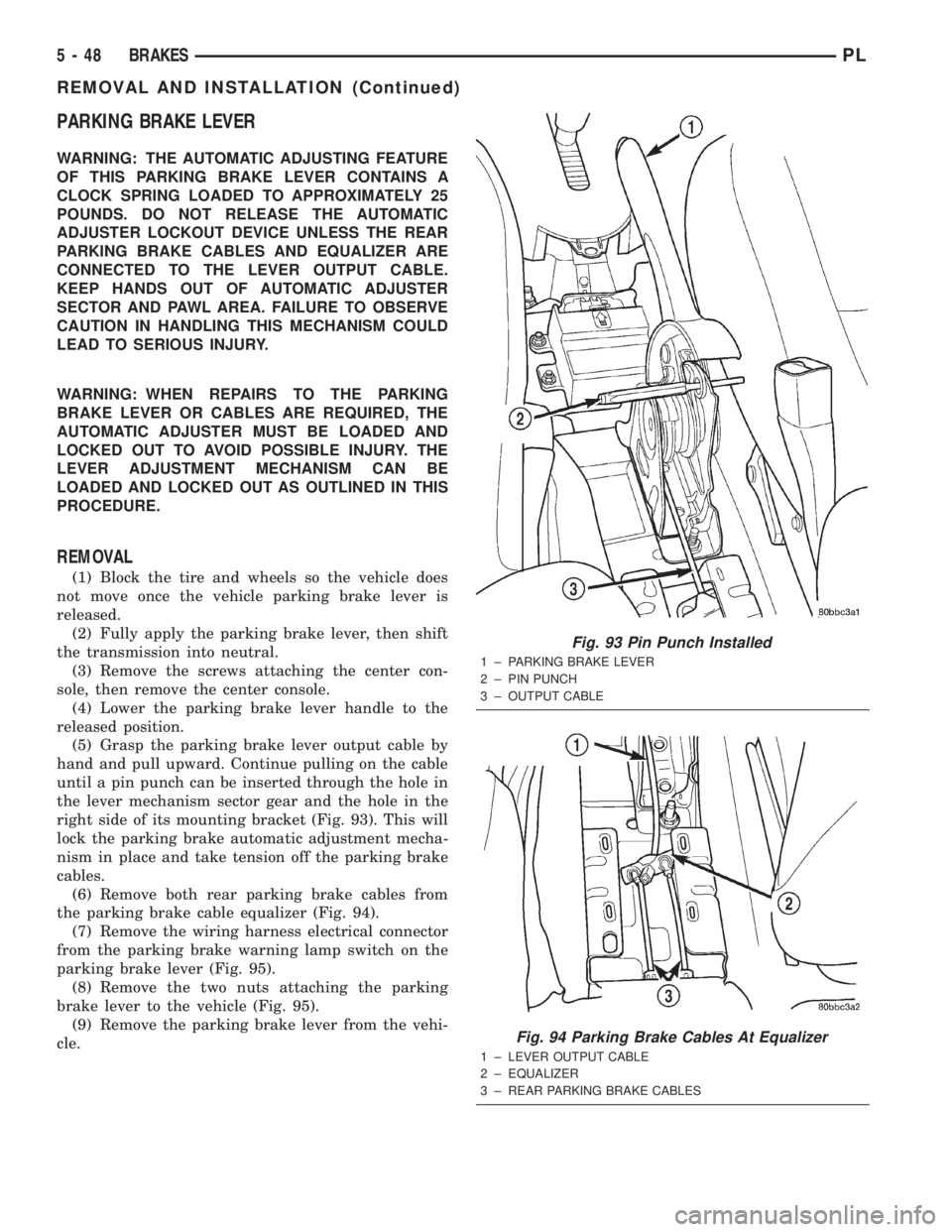
right side of its mounting bracket (Fig. 93). This will
lock the parking brake automatic adjustment mecha-
nism in place and take tension off the parking brake
cables.
(6) Remove both rear parking brake cables from
the parking brake cable equalizer (Fig. 94).
(7) Remove the wiring harness electrical connector
from the parking brake warning lamp switch on the
parking brake lever (Fig. 95).
(8) Remove the two nuts attaching the parking
brake lever to the vehicle (Fig. 95).
(9) Remove the parking brake lever from the vehi-
cle.
Fig. 93 Pin Punch Installed
1 ± PARKING BRAKE LEVER
2 ± PIN PUNCH
3 ± OUTPUT CABLE
Fig. 94 Parking Brake Cables At Equalizer
1 ± LEVER OUTPUT CABLE
2 ± EQUALIZER
3 ± REAR PARKING BRAKE CABLES
5 - 48 BRAKESPL
REMOVAL AND INSTALLATION (Continued)
Page 128 of 1285
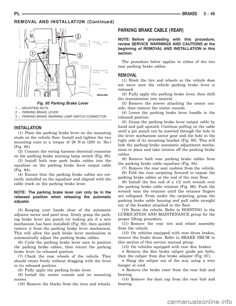
INSTALLATION
(1) Place the parking brake lever on the mounting
studs on the vehicle floor. Install and tighten the two
mounting nuts to a torque of 28 N´m (250 in. lbs.)
(Fig. 95).
(2) Connect the wiring harness electrical connector
on the parking brake warning lamp switch (Fig. 95).
(3) Install both rear park brake cables into the
equalizer on the parking brake lever output cable
(Fig. 94).
(4) Ensure that the parking brake cables are cor-
rectly installed on the equalizer and aligned with the
cable track on the parking brake lever.
NOTE: The parking brake lever can only be in the
released position when releasing the automatic
adjuster.
(5) Keeping your hands clear of the automatic
adjuster sector and pawl area, firmly grasp the park-
ing brake lever pin punch (or locking pin if a new
mechanism has been installed) (Fig. 93), then quickly
remove it from the parking brake lever mechanism.
This will allow the park brake lever mechanism to
automatically adjust the parking brake cables.
(6) Cycle the parking brake lever once to position
the parking brake cables, then return the parking
brake lever its released position.
(7) Check the rear wheels of the vehicle. They
should rotate freely without dragging with the lever
in its released position.
(8) Fully apply the parking brake lever.
(9) Install the center console and its mounting
screws.
(10) Remove the blocks from the tires and wheels.
PARKING BRAKE CABLE (REAR)
NOTE: Before proceeding with this procedure,
review SERVICE WARNINGS AND CAUTIONS at the
beginning of REMOVAL AND INSTALLATION in this
section.
The procedure below applies to either of the two
rear parking brake cables.
REMOVAL
(1) Block the tire and wheels so the vehicle does
not move once the vehicle parking brake lever is
released.
(2) Fully apply the parking brake lever, then shift
the transmission into neutral.
(3) Remove the screws attaching the center con-
sole, then remove the center console.
(4) Lower the parking brake lever handle to the
released position.
(5) Grasp the parking brake lever output cable by
hand and pull upward. Continue pulling on the cable
until a pin punch can be inserted through the hole in
the lever mechanism sector gear and the hole in the
right side of its mounting bracket (Fig. 93). This will
lock the parking brake automatic adjustment mecha-
nism in place and take tension off the parking brake
cables.
(6) Remove both rear parking brake cables from
the parking brake cable equalizer (Fig. 94).
(7) Remove the rear seat cushion from the vehicle.
(8) Fold the rear carpeting forward to expose the
parking brake cables at the end of the rear floor.
(9) Install the box end of a 1/2 inch wrench over
the parking brake cable retainer (Fig. 96). Push the
wrench onto the retainer until the retainer fingers
are collapsed. From under the carpeting, grasp the
parking brake cable housing and pull cable straight
out of the bracket attached to the floor.
(10) Raise the vehicle. Refer to HOISTING in the
LUBRICATION AND MAINTENANCE group for the
proper lifting procedure.
(11) Remove the rear tire and wheel assembly
from the vehicle.
(12) On vehicles equipped with rear drum brakes,
remove the brake drum. Refer to BRAKE DRUM in
this section of this service manual group.
(13) On vehicles equipped with rear disc brakes:
²Remove the disc brake caliper guide pin bolts,
then the caliper from disc brake adapter (Fig. 97).
²Hang the caliper out of the way using a wire
hanger or cord.
²Remove the brake rotor from the rear hub and
bearing.
(14) Remove the dust cap from the rear hub and
bearing.
Fig. 95 Parking Brake Lever
1 ± MOUNTING NUTS
2 ± PARKING BRAKE LEVER
3 ± PARKING BRAKE WARNING LAMP SWITCH CONNECTOR
PLBRAKES 5 - 49
REMOVAL AND INSTALLATION (Continued)
Page 142 of 1285
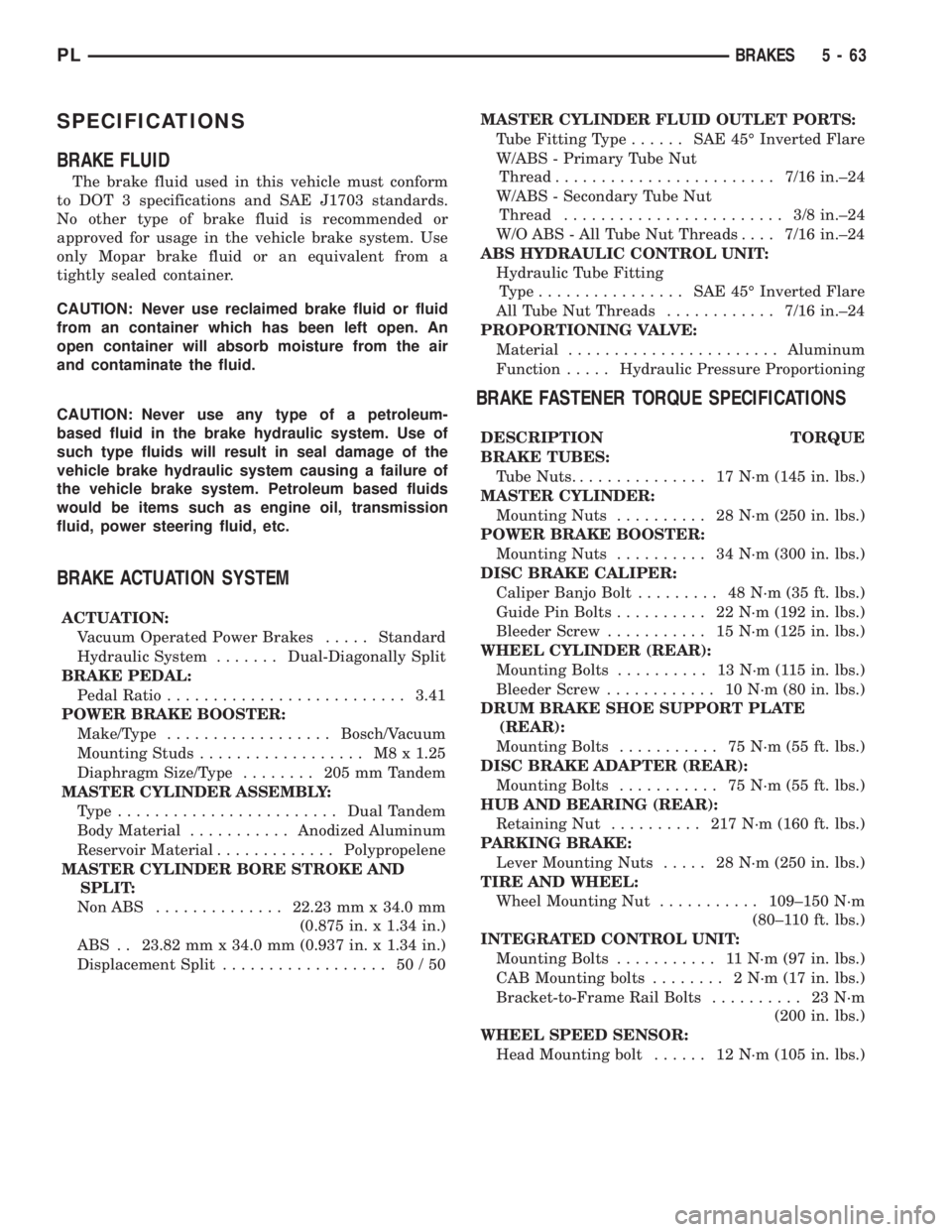
SPECIFICATIONS
BRAKE FLUID
The brake fluid used in this vehicle must conform
to DOT 3 specifications and SAE J1703 standards.
No other type of brake fluid is recommended or
approved for usage in the vehicle brake system. Use
only Mopar brake fluid or an equivalent from a
tightly sealed container.
CAUTION: Never use reclaimed brake fluid or fluid
from an container which has been left open. An
open container will absorb moisture from the air
and contaminate the fluid.
CAUTION: Never use any type of a petroleum-
based fluid in the brake hydraulic system. Use of
such type fluids will result in seal damage of the
vehicle brake hydraulic system causing a failure of
the vehicle brake system. Petroleum based fluids
would be items such as engine oil, transmission
fluid, power steering fluid, etc.
BRAKE ACTUATION SYSTEM
ACTUATION:
Vacuum Operated Power Brakes.....Standard
Hydraulic System.......Dual-Diagonally Split
BRAKE PEDAL:
Pedal Ratio..........................3.41
POWER BRAKE BOOSTER:
Make/Type..................Bosch/Vacuum
Mounting Studs.................. M8x1.25
Diaphragm Size/Type........ 205mmTandem
MASTER CYLINDER ASSEMBLY:
Type ........................Dual Tandem
Body Material...........Anodized Aluminum
Reservoir Material.............Polypropelene
MASTER CYLINDER BORE STROKE AND
SPLIT:
NonABS ..............22.23 mm x 34.0 mm
(0.875 in. x 1.34 in.)
ABS . . 23.82 mm x 34.0 mm (0.937 in. x 1.34 in.)
Displacement Split.................. 50/50MASTER CYLINDER FLUID OUTLET PORTS:
Tube Fitting Type...... SAE45ÉInverted Flare
W/ABS - Primary Tube Nut
Thread........................7/16 in.±24
W/ABS - Secondary Tube Nut
Thread........................ 3/8in.±24
W/O ABS - All Tube Nut Threads....7/16 in.±24
ABS HYDRAULIC CONTROL UNIT:
Hydraulic Tube Fitting
Type................ SAE45ÉInverted Flare
All Tube Nut Threads............7/16 in.±24
PROPORTIONING VALVE:
Material.......................Aluminum
Function.....Hydraulic Pressure Proportioning
BRAKE FASTENER TORQUE SPECIFICATIONS
DESCRIPTION TORQUE
BRAKE TUBES:
Tube Nuts............... 17N´m(145 in. lbs.)
MASTER CYLINDER:
Mounting Nuts.......... 28N´m(250 in. lbs.)
POWER BRAKE BOOSTER:
Mounting Nuts.......... 34N´m(300 in. lbs.)
DISC BRAKE CALIPER:
Caliper Banjo Bolt......... 48N´m(35ft.lbs.)
Guide Pin Bolts.......... 22N´m(192 in. lbs.)
Bleeder Screw........... 15N´m(125 in. lbs.)
WHEEL CYLINDER (REAR):
Mounting Bolts.......... 13N´m(115in.lbs.)
Bleeder Screw............ 10N´m(80in.lbs.)
DRUM BRAKE SHOE SUPPORT PLATE
(REAR):
Mounting Bolts........... 75N´m(55ft.lbs.)
DISC BRAKE ADAPTER (REAR):
Mounting Bolts........... 75N´m(55ft.lbs.)
HUB AND BEARING (REAR):
Retaining Nut.......... 217N´m(160 ft. lbs.)
PARKING BRAKE:
Lever Mounting Nuts..... 28N´m(250 in. lbs.)
TIRE AND WHEEL:
Wheel Mounting Nut...........109±150 N´m
(80±110 ft. lbs.)
INTEGRATED CONTROL UNIT:
Mounting Bolts........... 11N´m(97in.lbs.)
CAB Mounting bolts........ 2N´m(17in.lbs.)
Bracket-to-Frame Rail Bolts.......... 23N´m
(200 in. lbs.)
WHEEL SPEED SENSOR:
Head Mounting bolt...... 12N´m(105 in. lbs.)
PLBRAKES 5 - 63
Page 168 of 1285
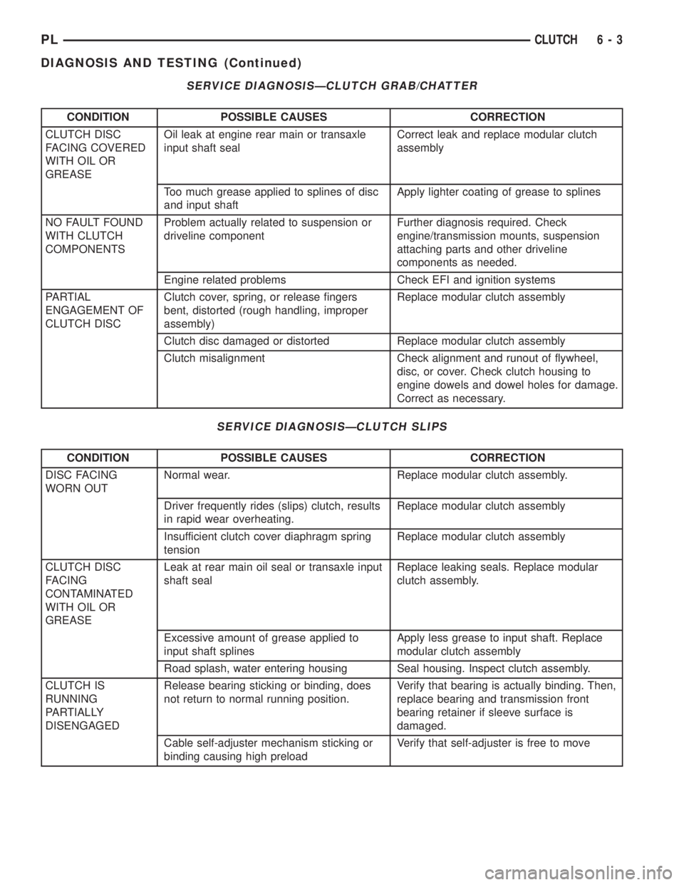
SERVICE DIAGNOSISÐCLUTCH GRAB/CHATTER
CONDITION POSSIBLE CAUSES CORRECTION
CLUTCH DISC
FACING COVERED
WITH OIL OR
GREASEOil leak at engine rear main or transaxle
input shaft sealCorrect leak and replace modular clutch
assembly
Too much grease applied to splines of disc
and input shaftApply lighter coating of grease to splines
NO FAULT FOUND
WITH CLUTCH
COMPONENTSProblem actually related to suspension or
driveline componentFurther diagnosis required. Check
engine/transmission mounts, suspension
attaching parts and other driveline
components as needed.
Engine related problems Check EFI and ignition systems
PARTIAL
ENGAGEMENT OF
CLUTCH DISCClutch cover, spring, or release fingers
bent, distorted (rough handling, improper
assembly)Replace modular clutch assembly
Clutch disc damaged or distorted Replace modular clutch assembly
Clutch misalignment Check alignment and runout of flywheel,
disc, or cover. Check clutch housing to
engine dowels and dowel holes for damage.
Correct as necessary.
SERVICE DIAGNOSISÐCLUTCH SLIPS
CONDITION POSSIBLE CAUSES CORRECTION
DISC FACING
WORN OUTNormal wear. Replace modular clutch assembly.
Driver frequently rides (slips) clutch, results
in rapid wear overheating.Replace modular clutch assembly
Insufficient clutch cover diaphragm spring
tensionReplace modular clutch assembly
CLUTCH DISC
FACING
CONTAMINATED
WITH OIL OR
GREASELeak at rear main oil seal or transaxle input
shaft sealReplace leaking seals. Replace modular
clutch assembly.
Excessive amount of grease applied to
input shaft splinesApply less grease to input shaft. Replace
modular clutch assembly
Road splash, water entering housing Seal housing. Inspect clutch assembly.
CLUTCH IS
RUNNING
PARTIALLY
DISENGAGEDRelease bearing sticking or binding, does
not return to normal running position.Verify that bearing is actually binding. Then,
replace bearing and transmission front
bearing retainer if sleeve surface is
damaged.
Cable self-adjuster mechanism sticking or
binding causing high preloadVerify that self-adjuster is free to move
PLCLUTCH 6 - 3
DIAGNOSIS AND TESTING (Continued)