2000 DODGE NEON fuel
[x] Cancel search: fuelPage 1 of 1285

GROUP TAB LOCATORINIntroductionINaIntroduction0Lubrication and Maintenance2Suspension3Differential and Driveline5Brakes6Clutch7Cooling8ABattery8BStarting8CCharging System8DIgnition System8EInstrument Panel and Systems8EaInstrument Panel and Systems8FAudio System8GHorns8HVehicle Speed Control System8JTurn Signal and Flashers8KWindshield Wipers and Washers8LLamps8LaLamps8MRestraint System8NElectrically Heated Systems8OPower Distribution Systems8PPower Door Locks8QImmobilizer System8SPower Windows8TPower Mirrors8TaPower Mirrors8UChime Warning/Reminder System8WWiring Diagrams - LHD and RHD9Engine11Exhaust System13Frame and Bumpers14Fuel System19Steering21Transaxle22Tires and Wheels23Body24Heating and Air Conditioning24aHeating and Air Conditioning25Emission Control Systems
Page 3 of 1285
LUBRICANTS AND GREASES
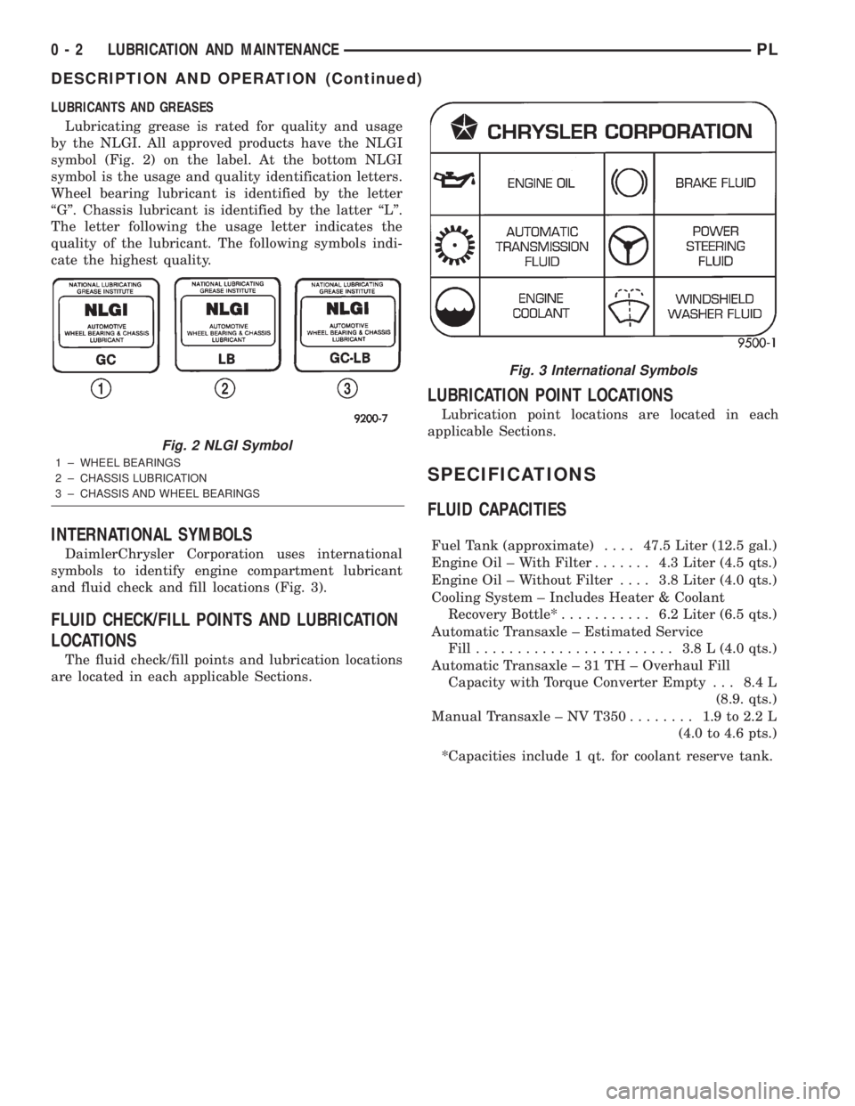
Lubricating grease is rated for quality and usage
by the NLGI. All approved products have the NLGI
symbol (Fig. 2) on the label. At the bottom NLGI
symbol is the usage and quality identification letters.
Wheel bearing lubricant is identified by the letter
ªGº. Chassis lubricant is identified by the latter ªLº.
The letter following the usage letter indicates the
quality of the lubricant. The following symbols indi-
cate the highest quality.
INTERNATIONAL SYMBOLS
DaimlerChrysler Corporation uses international
symbols to identify engine compartment lubricant
and fluid check and fill locations (Fig. 3).
FLUID CHECK/FILL POINTS AND LUBRICATION
LOCATIONS
The fluid check/fill points and lubrication locations
are located in each applicable Sections.
LUBRICATION POINT LOCATIONS
Lubrication point locations are located in each
applicable Sections.
SPECIFICATIONS
FLUID CAPACITIES
Fuel Tank (approximate)....47.5 Liter (12.5 gal.)
Engine Oil ± With Filter....... 4.3Liter (4.5 qts.)
Engine Oil ± Without Filter.... 3.8Liter (4.0 qts.)
Cooling System ± Includes Heater & Coolant
Recovery Bottle*........... 6.2Liter (6.5 qts.)
Automatic Transaxle ± Estimated Service
Fill........................ 3.8L(4.0 qts.)
Automatic Transaxle ± 31 TH ± Overhaul Fill
Capacity with Torque Converter Empty . . . 8.4 L
(8.9. qts.)
Manual Transaxle ± NV T350........ 1.9to2.2L
(4.0 to 4.6 pts.)
*Capacities include 1 qt. for coolant reserve tank.
Fig. 2 NLGI Symbol
1 ± WHEEL BEARINGS
2 ± CHASSIS LUBRICATION
3 ± CHASSIS AND WHEEL BEARINGS
Fig. 3 International Symbols
0 - 2 LUBRICATION AND MAINTENANCEPL
DESCRIPTION AND OPERATION (Continued)
Page 4 of 1285
MAINTENANCE SCHEDULES
TABLE OF CONTENTS
page page
DESCRIPTION AND OPERATION
MAINTENANCE SCHEDULES................3
SPECIFICATIONS
UNSCHEDULED INSPECTION................3SCHEDULE ± A...........................3
SCHEDULE ± B...........................4
DESCRIPTION AND OPERATION
MAINTENANCE SCHEDULES
There are two maintenance schedules that show
proper service for your vehicle.
First is Schedule ±A. It lists all the scheduled
maintenance to be performed under ªnormalº operat-
ing conditions.
Second is Schedule ±B. It is a schedule for vehi-
cles that are operated under the following conditions:
²Frequent short trip driving less than 5 miles (8
km)
²Frequent driving in dusty conditions
²Extensive idling
²More than 50% of the driving is at sustained
high speeds during hot weather, above 90É F (32É C)
SPECIFICATIONS
UNSCHEDULED INSPECTION
At Each Stop For Fuel
²Check engine oil level and add as required.
²Check windshield washer solvent and add as
required.
Once A Month
²Check tire pressure and look for unusual wear
or damage.
²Inspect the battery and clean and tighten termi-
nals as required.
²Check fluid levels of coolant reservoir, brake
master cylinder, power steering and transmission.
Add fluid as required.
²Check all lights and all other electrical items for
correct operation.
At Each Oil Change
²Inspect the exhaust system.
²Inspect brake hoses.
²Inspect the CV joints and front suspension com-
ponent boots and seals.²Rotate the tires at each oil change interval
shown on Schedule ± A (7,500 miles - 12 000 km) or
every other interval on Schedule ± B (6,000 miles -
10 000 km).
²Check the engine coolant level, hoses, and
clamps.
If mileage is less than 7,500 miles (12 000 km)
yearly, replace the engine oil filter at each oil change.
EMISSION CONTROL SYSTEM MAINTENANCE
The scheduled emission maintenance listed inbold
typeon the Maintenance Schedules, must be done at
the mileage specified to assure the continued proper
functioning of the emission control system. These,
and all other maintenance services included in this
manual, should be done to provide the best vehicle
performance and reliability. More frequent mainte-
nance may be needed for vehicles in severe operating
conditions such as dusty areas and very short trip
driving.
FLUID FILL POINTS AND LUBRICATION
LOCATIONS
The fluid fill/check locations and lubrication loca-
tions are located in each applicable group.
SCHEDULE ± A
7,500 Miles (12 000 km) or at 6 months
²Change the engine oil.
²Replace the engine oil filter.
15,000 Miles (24 000 km) or at 12 months
²Change the engine oil.
²Replace the engine oil filter.
²Adjust the drive belt tension.
22,500 Miles (36 000 km) or at 18 months
²Change the engine oil.
²Replace the engine oil filter.
²Inspect the front brake pads and rear brake lin-
ings.
PLLUBRICATION AND MAINTENANCE 0 - 3
Page 8 of 1285

JUMP STARTING, TOWING, AND HOISTING
TABLE OF CONTENTS
page page
DESCRIPTION AND OPERATION
JUMP STARTING PROCEDURE...............7
TOWING RECOMMENDATIONS...............7
HOISTING RECOMMENDATIONS.............7SERVICE PROCEDURES
JUMP STARTING PROCEDURE...............7
TOWING RECOMMENDATIONS...............8
HOISTING RECOMMENDATIONS.............9
DESCRIPTION AND OPERATION
JUMP STARTING PROCEDURE
Describes the procedure for starting a disable vehi-
cle.
TOWING RECOMMENDATIONS
Describes the recommended towing procedures.
HOISTING RECOMMENDATIONS
Describes the location of hoisting and jacking
points so that the vehicle can be lifted by a floor jack
or hoist.
SERVICE PROCEDURES
JUMP STARTING PROCEDURE
WARNING: REVIEW ALL SAFETY PRECAUTIONS
AND WARNINGS IN GROUP 8A, BATTERY/START-
ING/CHARGING SYSTEMS DIAGNOSTICS. DO NOT
JUMP START A FROZEN BATTERY, PERSONAL
INJURY CAN RESULT. DO NOT JUMP START WHEN
MAINTENANCE FREE BATTERY INDICATOR DOT IS
YELLOW OR BRIGHT COLOR. DO NOT JUMP
START A VEHICLE WHEN THE BATTERY FLUID IS
BELOW THE TOP OF LEAD PLATES. DO NOT
ALLOW JUMPER CABLE CLAMPS TO TOUCH
EACH OTHER WHEN CONNECTED TO A BOOSTER
SOURCE. DO NOT USE OPEN FLAME NEAR BAT-
TERY. REMOVE METALLIC JEWELRY WORN ON
HANDS OR WRISTS TO AVOID INJURY BY ACCI-
DENTAL ARCING OF BATTERY CURRENT. WHEN
USING A HIGH OUTPUT BOOSTING DEVICE, DO
NOT ALLOW BATTERY VOLTAGE TO EXCEED 16
VOLTS. REFER TO INSTRUCTIONS PROVIDED
WITH DEVICE BEING USED.
CAUTION: When using another vehicle as a
booster, do not allow vehicles to touch. Electrical
systems can be damaged on either vehicle.
TO JUMP START A DISABLED VEHICLE:
(1) Raise hood on disabled vehicle and visually
inspect engine compartment for:
²Battery cable clamp condition, clean if necessary.
²Frozen battery.
²Yellow or bright color test indicator, if equipped.
²Low battery fluid level.
²Generator drive belt condition and tension.
²Fuel fumes or leakage, correct if necessary.
CAUTION: If the cause of starting problem on dis-
abled vehicle is severe, damage to booster vehicle
charging system can result.
(2) When using another vehicle as a booster
source, park the booster vehicle within cable reach.
Turn off all accessories, set the parking brake, place
the automatic transmission in PARK or the manual
transmission in NEUTRAL and turn the ignition
OFF.
(3) On disabled vehicle, place gear selector in park
or neutral and set park brake. Turn off all accesso-
ries.
(4) Connect jumper cables to booster battery. RED
clamp to positive terminal (+). BLACK clamp to neg-
ative terminal (-). DO NOT allow clamps at opposite
end of cables to touch, electrical arc will result.
Review all warnings in this procedure.
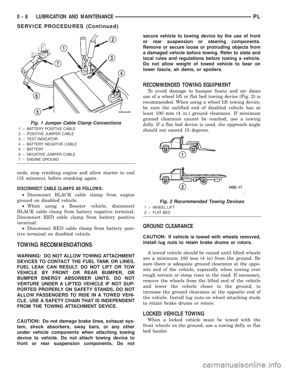
(5) On disabled vehicle, connect RED jumper cable
clamp to positive (+) terminal. Connect BLACK
jumper cable clamp to engine ground as close to the
ground cable attaching point as possible (Fig. 1).
(6) Start the engine in the vehicle which has the
booster battery, let the engine idle a few minutes,
then start the engine in the vehicle with the dis-
charged battery.
CAUTION: Do not crank starter motor on disabled
vehicle for more than 15 seconds, starter will over-
heat and could fail.
(7) Allow battery in disabled vehicle to charge to
at least 12.4 volts (75% charge) before attempting to
start engine. If engine does not start within 15 sec-
PLLUBRICATION AND MAINTENANCE 0 - 7
Page 9 of 1285
onds, stop cranking engine and allow starter to cool
(15 minutes), before cranking again.
DISCONNECT CABLE CLAMPS AS FOLLOWS:
²Disconnect BLACK cable clamp from engine
ground on disabled vehicle.
²When using a Booster vehicle, disconnect
BLACK cable clamp from battery negative terminal.
Disconnect RED cable clamp from battery positive
terminal.
²Disconnect RED cable clamp from battery posi-
tive terminal on disabled vehicle.
TOWING RECOMMENDATIONS
WARNING: DO NOT ALLOW TOWING ATTACHMENT
DEVICES TO CONTACT THE FUEL TANK OR LINES,
FUEL LEAK CAN RESULT. DO NOT LIFT OR TOW
VEHICLE BY FRONT OR REAR BUMPER, OR
BUMPER ENERGY ABSORBER UNITS. DO NOT
VENTURE UNDER A LIFTED VEHICLE IF NOT SUP-
PORTED PROPERLY ON SAFETY STANDS. DO NOT
ALLOW PASSENGERS TO RIDE IN A TOWED VEHI-
CLE. USE A SAFETY CHAIN THAT IS INDEPENDENT
FROM THE TOWING ATTACHMENT DEVICE.
CAUTION: Do not damage brake lines, exhaust sys-
tem, shock absorbers, sway bars, or any other
under vehicle components when attaching towing
device to vehicle. Do not attach towing device to
front or rear suspension components. Do notsecure vehicle to towing device by the use of front
or rear suspension or steering components.
Remove or secure loose or protruding objects from
a damaged vehicle before towing. Refer to state and
local rules and regulations before towing a vehicle.
Do not allow weight of towed vehicle to bear on
lower fascia, air dams, or spoilers.
RECOMMENDED TOWING EQUIPMENT
To avoid damage to bumper fascia and air dams
use of a wheel lift or flat bed towing device (Fig. 2) is
recommended. When using a wheel lift towing device,
be sure the unlifted end of disabled vehicle has at
least 100 mm (4 in.) ground clearance. If minimum
ground clearance cannot be reached, use a towing
dolly. If a flat bed device is used, the approach angle
should not exceed 15 degrees.
GROUND CLEARANCE
CAUTION: If vehicle is towed with wheels removed,
install lug nuts to retain brake drums or rotors.
A towed vehicle should be raised until lifted wheels
are a minimum 100 mm (4 in) from the ground. Be
sure there is adequate ground clearance at the oppo-
site end of the vehicle, especially when towing over
rough terrain or steep rises in the road. If necessary,
remove the wheels from the lifted end of the vehicle
and lower the vehicle closer to the ground, to
increase the ground clearance at the opposite end of
the vehicle. Install lug nuts on wheel attaching studs
to retain brake drums or rotors.
LOCKED VEHICLE TOWING
When a locked vehicle must be towed with the
front wheels on the ground, use a towing dolly or flat
bed hauler.
Fig. 1 Jumper Cable Clamp Connections
1 ± BATTERY POSITIVE CABLE
2 ± POSITIVE JUMPER CABLE
3 ± TEST INDICATOR
4 ± BATTERY NEGATIVE CABLE
5 ± BATTERY
6 ± NEGATIVE JUMPER CABLE
7 ± ENGINE GROUND
Fig. 2 Recommended Towing Devices
1 ± WHEEL LIFT
2 ± FLAT BED
0 - 8 LUBRICATION AND MAINTENANCEPL
SERVICE PROCEDURES (Continued)
Page 16 of 1285
SERVICE PROCEDURES
CURB HEIGHT MEASUREMENT
The wheel alignment is to be checked and all align-
ment adjustments made with the vehicle at its
required curb height specification.
Vehicle height is to be checked with the vehicle on
a flat, level surface, preferably a vehicle alignment
rack. The tires are to be inflated to the recommended
pressure. All tires are to be the same size as stan-
dard equipment. Vehicle height is checked with the
fuel tank full of fuel, and no passenger or luggage
compartment load.
Vehicle height is not adjustable. If the measure-
ment is not within specifications, inspect the vehicle
for bent or weak suspension components. Compare
the parts tag on the suspect coil spring(s) to the
parts book and the vehicle sales code, checking for a
match. Once removed from the vehicle, compare thecoil spring height to a correct new or known good coil
spring. The heights should vary if the suspect spring
is weak.
NOTE: Prior to reading the curb height measure-
ment, the front an rear of the vehicle should be
jounced. Induce jounce by grasping the center of
the rear, then front bumper (or fascia) and jouncing
the vehicle an equal number of times. Release the
bumper at the bottom of the jounce cycle.
(1) Measure from the inboard edge of the wheel
opening fender lip directly above the wheel center
(spindle), to the floor or alignment rack surface.
(2) When measuring, maximum left-to-right differ-
ential is not to exceed 10 mm (0.39 in.).
(3) Compare the measurements to specifications
listed in the following CURB HEIGHT SPECIFICA-
TIONS chart.
CURB HEIGHT SPECIFICATIONS
VEHICLE FRONT REAR
ALL NEON672 mm68 mm 679 mm68mm
26.46 in.60.32 in. 26.73 in.60.32 in.
WHEEL ALIGNMENT
PRE-WHEEL ALIGNMENT VEHICLE INSPECTION
CAUTION: If during the inspection the front sus-
pension crossmember shows any sign of impact
damage, the steering column lower coupling must
be inspected. Refer to DIAGNOSIS AND TESTING in
the STEERING group in this service manual.
Before any attempt is made to change or correct
the wheel alignment, the following inspection and
necessary corrections must be made to the vehicle to
ensure proper alignment.
(1) Be sure the fuel tank is full of fuel. If the fuel
tank is not full, the reduction in weight will affect
the curb height of the vehicle and the alignment
specifications.
(2) The passenger and luggage compartments of
the vehicle should be free of any load that is not fac-
tory equipment.
(3) Check the tires on the vehicle. The tires are to
be inflated to the recommended air pressure. All tires
must be the same size and in good condition with
approximately the same tread wear.
(4) Check the front tire and wheel assemblies for
excessive radial runout.(5) Inspect all suspension component fasteners for
looseness and torque.
(6) Inspect the lower front ball joints and all steer-
ing linkage for looseness and any sign of wear or
damage.
(7) Inspect the rubber bushings on all the suspen-
sion components for signs of wear or deterioration. If
any bushings show signs of wear or deterioration,
they should be replaced prior to aligning the vehicle.
WHEEL ALIGNMENT SETUP
(1) Position the vehicle on an alignment rack.
(2) Install all required alignment equipment on
the vehicle, per the alignment equipment manufac-
turer's instructions. On this vehicle, a four-wheel
alignment is recommended.
NOTE: Prior to reading the vehicle's alignment
readouts, the front and rear of vehicle should be
jounced. Induce jounce (rear first, then front) by
grasping the center of the bumper and jouncing
each end of vehicle an equal number of times. The
bumper should always be released when vehicle is
at the bottom of the jounce cycle.
(3) Read the vehicle's current front and rear align-
ment settings. Compare the vehicle's current align-
ment settings to the vehicle specifications for camber,
caster and toe-in. Refer to WHEEL ALIGNMENT
PLSUSPENSION 2 - 5
Page 162 of 1285
WHEEL SPEED SENSOR (REAR)
NOTE: Before proceeding with this procedure,
review SERVICE WARNINGS AND CAUTIONS at the
beginning of REMOVAL AND INSTALLATION in this
section.
REMOVAL
(1) Raise the vehicle. Refer to HOISTING in the
LUBRICATION AND MAINTENANCE group for the
proper lifting procedure.
(2) Remove the tire and wheel assembly from the
vehicle.
(3) Disconnect the wheel speed sensor cable con-
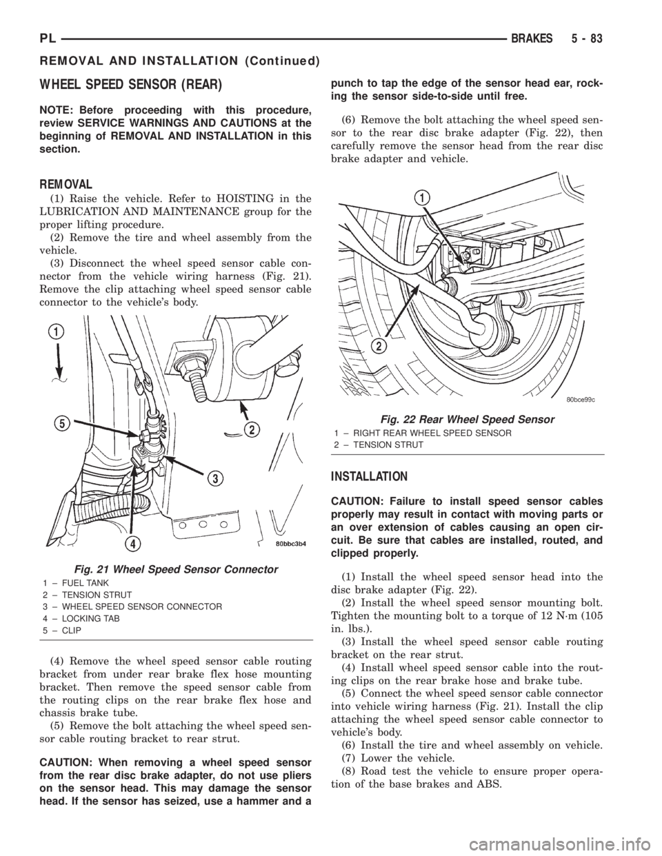
nector from the vehicle wiring harness (Fig. 21).
Remove the clip attaching wheel speed sensor cable
connector to the vehicle's body.
(4) Remove the wheel speed sensor cable routing
bracket from under rear brake flex hose mounting
bracket. Then remove the speed sensor cable from
the routing clips on the rear brake flex hose and
chassis brake tube.
(5) Remove the bolt attaching the wheel speed sen-
sor cable routing bracket to rear strut.
CAUTION: When removing a wheel speed sensor
from the rear disc brake adapter, do not use pliers
on the sensor head. This may damage the sensor
head. If the sensor has seized, use a hammer and apunch to tap the edge of the sensor head ear, rock-
ing the sensor side-to-side until free.
(6) Remove the bolt attaching the wheel speed sen-
sor to the rear disc brake adapter (Fig. 22), then
carefully remove the sensor head from the rear disc
brake adapter and vehicle.
INSTALLATION
CAUTION: Failure to install speed sensor cables
properly may result in contact with moving parts or
an over extension of cables causing an open cir-
cuit. Be sure that cables are installed, routed, and
clipped properly.
(1) Install the wheel speed sensor head into the
disc brake adapter (Fig. 22).
(2) Install the wheel speed sensor mounting bolt.
Tighten the mounting bolt to a torque of 12 N´m (105
in. lbs.).
(3) Install the wheel speed sensor cable routing
bracket on the rear strut.
(4) Install wheel speed sensor cable into the rout-
ing clips on the rear brake hose and brake tube.
(5) Connect the wheel speed sensor cable connector
into vehicle wiring harness (Fig. 21). Install the clip
attaching the wheel speed sensor cable connector to
vehicle's body.
(6) Install the tire and wheel assembly on vehicle.
(7) Lower the vehicle.
(8) Road test the vehicle to ensure proper opera-
tion of the base brakes and ABS.
Fig. 21 Wheel Speed Sensor Connector
1 ± FUEL TANK
2 ± TENSION STRUT
3 ± WHEEL SPEED SENSOR CONNECTOR
4 ± LOCKING TAB
5 ± CLIP
Fig. 22 Rear Wheel Speed Sensor
1 ± RIGHT REAR WHEEL SPEED SENSOR
2 ± TENSION STRUT
PLBRAKES 5 - 83
REMOVAL AND INSTALLATION (Continued)
Page 187 of 1285
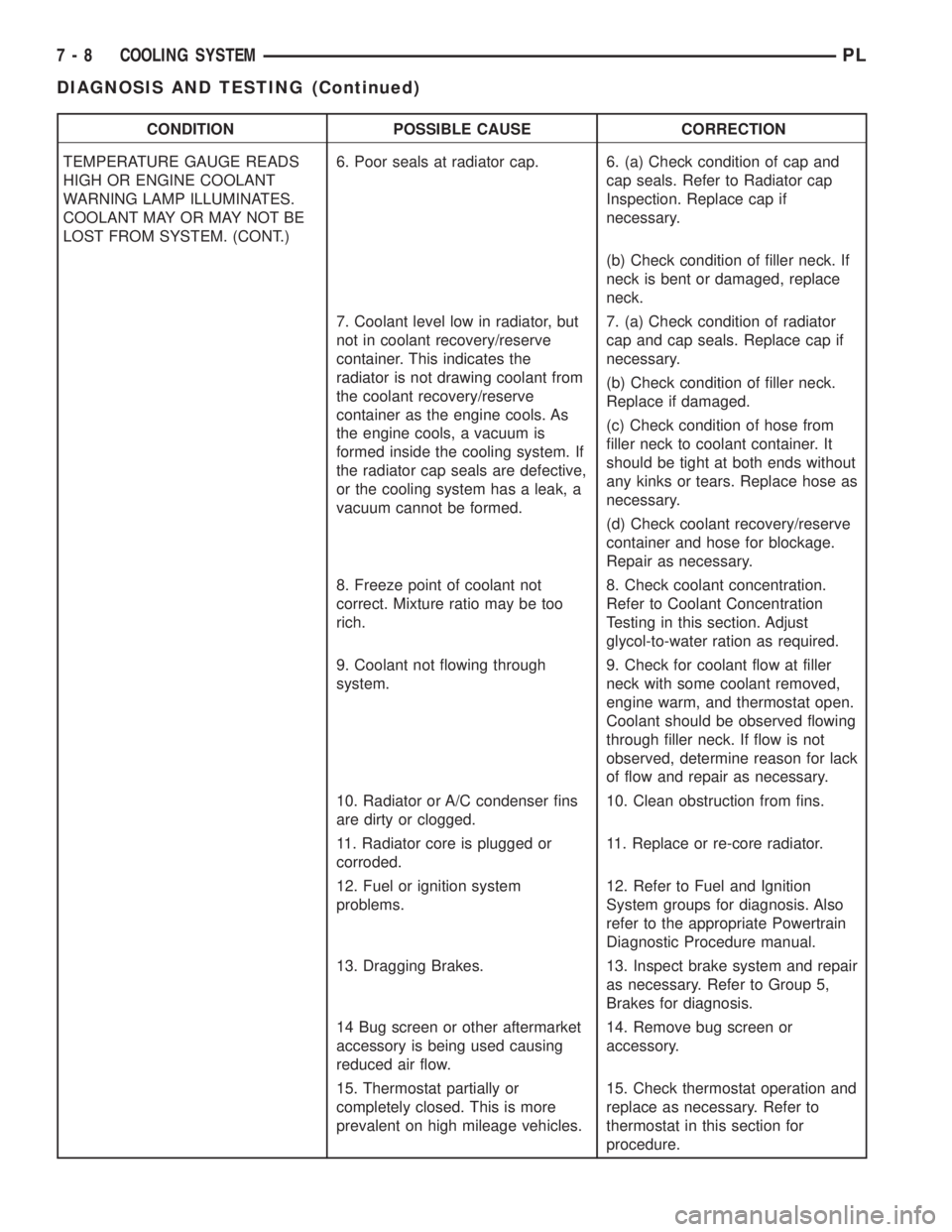
CONDITION POSSIBLE CAUSE CORRECTION
TEMPERATURE GAUGE READS
HIGH OR ENGINE COOLANT
WARNING LAMP ILLUMINATES.
COOLANT MAY OR MAY NOT BE
LOST FROM SYSTEM. (CONT.)6. Poor seals at radiator cap. 6. (a) Check condition of cap and
cap seals. Refer to Radiator cap
Inspection. Replace cap if
necessary.
(b) Check condition of filler neck. If
neck is bent or damaged, replace
neck.
7. Coolant level low in radiator, but
not in coolant recovery/reserve
container. This indicates the
radiator is not drawing coolant from
the coolant recovery/reserve
container as the engine cools. As
the engine cools, a vacuum is
formed inside the cooling system. If
the radiator cap seals are defective,
or the cooling system has a leak, a
vacuum cannot be formed.7. (a) Check condition of radiator
cap and cap seals. Replace cap if
necessary.
(b) Check condition of filler neck.
Replace if damaged.
(c) Check condition of hose from
filler neck to coolant container. It
should be tight at both ends without
any kinks or tears. Replace hose as
necessary.
(d) Check coolant recovery/reserve
container and hose for blockage.
Repair as necessary.
8. Freeze point of coolant not
correct. Mixture ratio may be too
rich.8. Check coolant concentration.
Refer to Coolant Concentration
Testing in this section. Adjust
glycol-to-water ration as required.
9. Coolant not flowing through
system.9. Check for coolant flow at filler
neck with some coolant removed,
engine warm, and thermostat open.
Coolant should be observed flowing
through filler neck. If flow is not
observed, determine reason for lack
of flow and repair as necessary.
10. Radiator or A/C condenser fins
are dirty or clogged.10. Clean obstruction from fins.
11. Radiator core is plugged or
corroded.11. Replace or re-core radiator.
12. Fuel or ignition system
problems.12. Refer to Fuel and Ignition
System groups for diagnosis. Also
refer to the appropriate Powertrain
Diagnostic Procedure manual.
13. Dragging Brakes. 13. Inspect brake system and repair
as necessary. Refer to Group 5,
Brakes for diagnosis.
14 Bug screen or other aftermarket
accessory is being used causing
reduced air flow.14. Remove bug screen or
accessory.
15. Thermostat partially or
completely closed. This is more
prevalent on high mileage vehicles.15. Check thermostat operation and
replace as necessary. Refer to
thermostat in this section for
procedure.
7 - 8 COOLING SYSTEMPL
DIAGNOSIS AND TESTING (Continued)