2000 DODGE NEON lights
[x] Cancel search: lightsPage 4 of 1285
MAINTENANCE SCHEDULES
TABLE OF CONTENTS
page page
DESCRIPTION AND OPERATION
MAINTENANCE SCHEDULES................3
SPECIFICATIONS
UNSCHEDULED INSPECTION................3SCHEDULE ± A...........................3
SCHEDULE ± B...........................4
DESCRIPTION AND OPERATION
MAINTENANCE SCHEDULES
There are two maintenance schedules that show
proper service for your vehicle.
First is Schedule ±A. It lists all the scheduled
maintenance to be performed under ªnormalº operat-
ing conditions.
Second is Schedule ±B. It is a schedule for vehi-
cles that are operated under the following conditions:
²Frequent short trip driving less than 5 miles (8
km)
²Frequent driving in dusty conditions
²Extensive idling
²More than 50% of the driving is at sustained
high speeds during hot weather, above 90É F (32É C)
SPECIFICATIONS
UNSCHEDULED INSPECTION
At Each Stop For Fuel
²Check engine oil level and add as required.
²Check windshield washer solvent and add as
required.
Once A Month
²Check tire pressure and look for unusual wear
or damage.
²Inspect the battery and clean and tighten termi-
nals as required.
²Check fluid levels of coolant reservoir, brake
master cylinder, power steering and transmission.
Add fluid as required.
²Check all lights and all other electrical items for
correct operation.
At Each Oil Change
²Inspect the exhaust system.
²Inspect brake hoses.
²Inspect the CV joints and front suspension com-
ponent boots and seals.²Rotate the tires at each oil change interval
shown on Schedule ± A (7,500 miles - 12 000 km) or
every other interval on Schedule ± B (6,000 miles -
10 000 km).
²Check the engine coolant level, hoses, and
clamps.
If mileage is less than 7,500 miles (12 000 km)
yearly, replace the engine oil filter at each oil change.
EMISSION CONTROL SYSTEM MAINTENANCE
The scheduled emission maintenance listed inbold
typeon the Maintenance Schedules, must be done at
the mileage specified to assure the continued proper
functioning of the emission control system. These,
and all other maintenance services included in this
manual, should be done to provide the best vehicle
performance and reliability. More frequent mainte-
nance may be needed for vehicles in severe operating
conditions such as dusty areas and very short trip
driving.
FLUID FILL POINTS AND LUBRICATION
LOCATIONS
The fluid fill/check locations and lubrication loca-
tions are located in each applicable group.
SCHEDULE ± A
7,500 Miles (12 000 km) or at 6 months
²Change the engine oil.
²Replace the engine oil filter.
15,000 Miles (24 000 km) or at 12 months
²Change the engine oil.
²Replace the engine oil filter.
²Adjust the drive belt tension.
22,500 Miles (36 000 km) or at 18 months
²Change the engine oil.
²Replace the engine oil filter.
²Inspect the front brake pads and rear brake lin-
ings.
PLLUBRICATION AND MAINTENANCE 0 - 3
Page 212 of 1285
DIAGNOSIS AND TESTING
BATTERY BUILT-IN TEST INDICATOR
USING TEST INDICATOR
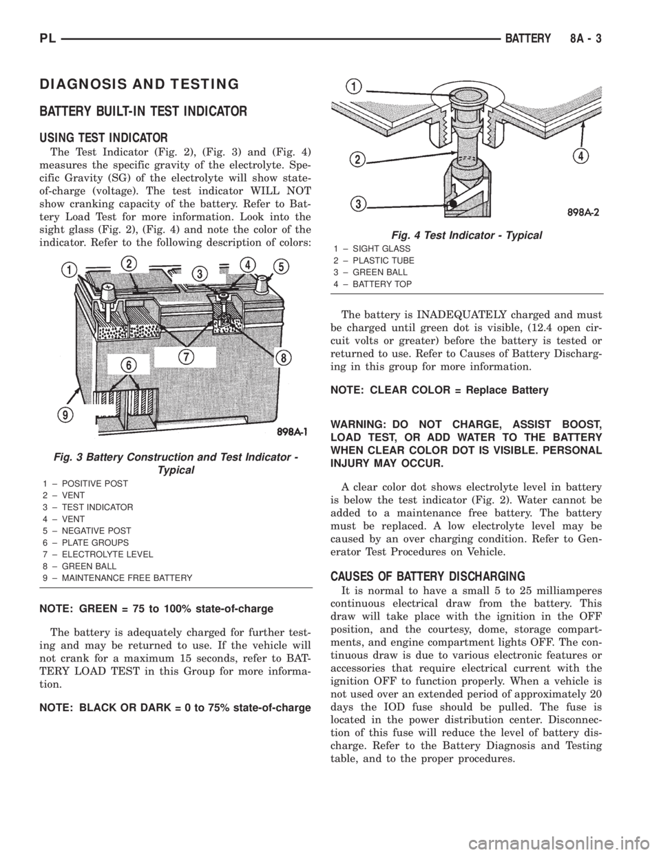
The Test Indicator (Fig. 2), (Fig. 3) and (Fig. 4)
measures the specific gravity of the electrolyte. Spe-
cific Gravity (SG) of the electrolyte will show state-
of-charge (voltage). The test indicator WILL NOT
show cranking capacity of the battery. Refer to Bat-
tery Load Test for more information. Look into the
sight glass (Fig. 2), (Fig. 4) and note the color of the
indicator. Refer to the following description of colors:
NOTE: GREEN = 75 to 100% state-of-charge
The battery is adequately charged for further test-
ing and may be returned to use. If the vehicle will
not crank for a maximum 15 seconds, refer to BAT-
TERY LOAD TEST in this Group for more informa-
tion.
NOTE: BLACK OR DARK=0to75%state-of-chargeThe battery is INADEQUATELY charged and must
be charged until green dot is visible, (12.4 open cir-
cuit volts or greater) before the battery is tested or
returned to use. Refer to Causes of Battery Discharg-
ing in this group for more information.
NOTE: CLEAR COLOR = Replace Battery
WARNING: DO NOT CHARGE, ASSIST BOOST,
LOAD TEST, OR ADD WATER TO THE BATTERY
WHEN CLEAR COLOR DOT IS VISIBLE. PERSONAL
INJURY MAY OCCUR.
A clear color dot shows electrolyte level in battery
is below the test indicator (Fig. 2). Water cannot be
added to a maintenance free battery. The battery
must be replaced. A low electrolyte level may be
caused by an over charging condition. Refer to Gen-
erator Test Procedures on Vehicle.
CAUSES OF BATTERY DISCHARGING
It is normal to have a small 5 to 25 milliamperes
continuous electrical draw from the battery. This
draw will take place with the ignition in the OFF
position, and the courtesy, dome, storage compart-
ments, and engine compartment lights OFF. The con-
tinuous draw is due to various electronic features or
accessories that require electrical current with the
ignition OFF to function properly. When a vehicle is
not used over an extended period of approximately 20
days the IOD fuse should be pulled. The fuse is
located in the power distribution center. Disconnec-
tion of this fuse will reduce the level of battery dis-
charge. Refer to the Battery Diagnosis and Testing
table, and to the proper procedures.
Fig. 3 Battery Construction and Test Indicator -
Typical
1 ± POSITIVE POST
2 ± VENT
3 ± TEST INDICATOR
4 ± VENT
5 ± NEGATIVE POST
6 ± PLATE GROUPS
7 ± ELECTROLYTE LEVEL
8 ± GREEN BALL
9 ± MAINTENANCE FREE BATTERY
Fig. 4 Test Indicator - Typical
1 ± SIGHT GLASS
2 ± PLASTIC TUBE
3 ± GREEN BALL
4 ± BATTERY TOP
PLBATTERY 8A - 3
Page 214 of 1285
be checked. To determine if a high current draw con-
dition exists first check the vehicle with a test lamp.
(1) Verify that all electrical accessories are OFF.
²Remove key from ignition switch
²Turn off all lights
²Trunk lid is closed
²Engine compartment hood lamp is disconnected
or lamp removed
²Map lamp on rear view mirror
²Glove box door is closed
²Sun visor vanity lights are OFF
²All doors are closed
²Allow the ignition key lamp system to time out
in approximately 30 seconds, if equipped.
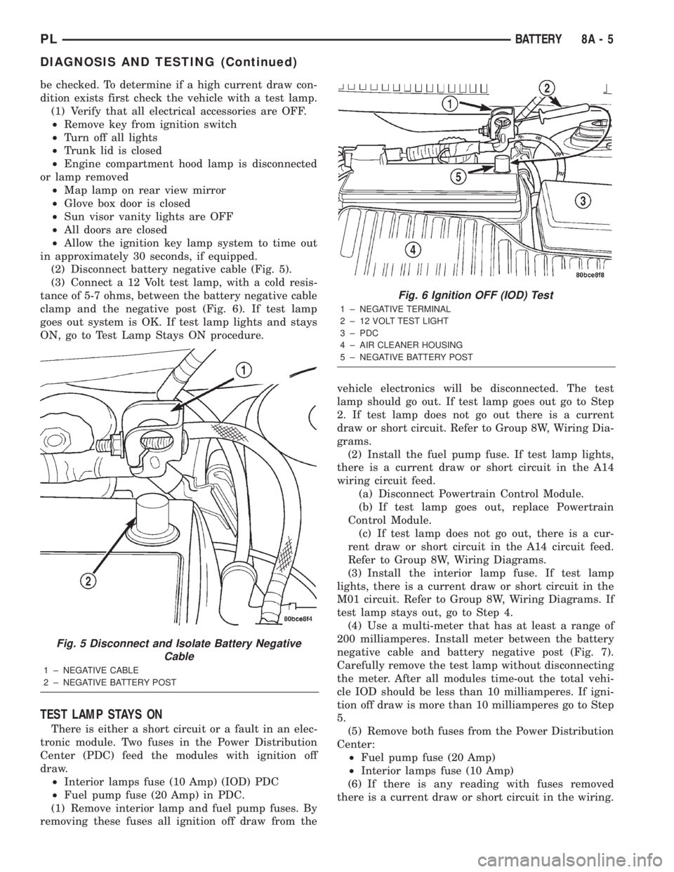
(2) Disconnect battery negative cable (Fig. 5).
(3) Connect a 12 Volt test lamp, with a cold resis-
tance of 5-7 ohms, between the battery negative cable
clamp and the negative post (Fig. 6). If test lamp
goes out system is OK. If test lamp lights and stays
ON, go to Test Lamp Stays ON procedure.
TEST LAMP STAYS ON
There is either a short circuit or a fault in an elec-
tronic module. Two fuses in the Power Distribution
Center (PDC) feed the modules with ignition off
draw.
²Interior lamps fuse (10 Amp) (IOD) PDC
²Fuel pump fuse (20 Amp) in PDC.
(1) Remove interior lamp and fuel pump fuses. By
removing these fuses all ignition off draw from thevehicle electronics will be disconnected. The test
lamp should go out. If test lamp goes out go to Step
2. If test lamp does not go out there is a current
draw or short circuit. Refer to Group 8W, Wiring Dia-
grams.
(2) Install the fuel pump fuse. If test lamp lights,
there is a current draw or short circuit in the A14
wiring circuit feed.
(a) Disconnect Powertrain Control Module.
(b) If test lamp goes out, replace Powertrain
Control Module.
(c) If test lamp does not go out, there is a cur-
rent draw or short circuit in the A14 circuit feed.
Refer to Group 8W, Wiring Diagrams.
(3) Install the interior lamp fuse. If test lamp
lights, there is a current draw or short circuit in the
M01 circuit. Refer to Group 8W, Wiring Diagrams. If
test lamp stays out, go to Step 4.
(4) Use a multi-meter that has at least a range of
200 milliamperes. Install meter between the battery
negative cable and battery negative post (Fig. 7).
Carefully remove the test lamp without disconnecting
the meter. After all modules time-out the total vehi-
cle IOD should be less than 10 milliamperes. If igni-
tion off draw is more than 10 milliamperes go to Step
5.
(5) Remove both fuses from the Power Distribution
Center:
²Fuel pump fuse (20 Amp)
²Interior lamps fuse (10 Amp)
(6) If there is any reading with fuses removed
there is a current draw or short circuit in the wiring.
Fig. 5 Disconnect and Isolate Battery Negative
Cable
1 ± NEGATIVE CABLE
2 ± NEGATIVE BATTERY POST
Fig. 6 Ignition OFF (IOD) Test
1 ± NEGATIVE TERMINAL
2 ± 12 VOLT TEST LIGHT
3 ± PDC
4 ± AIR CLEANER HOUSING
5 ± NEGATIVE BATTERY POST
PLBATTERY 8A - 5
DIAGNOSIS AND TESTING (Continued)
Page 226 of 1285
FEED CIRCUIT
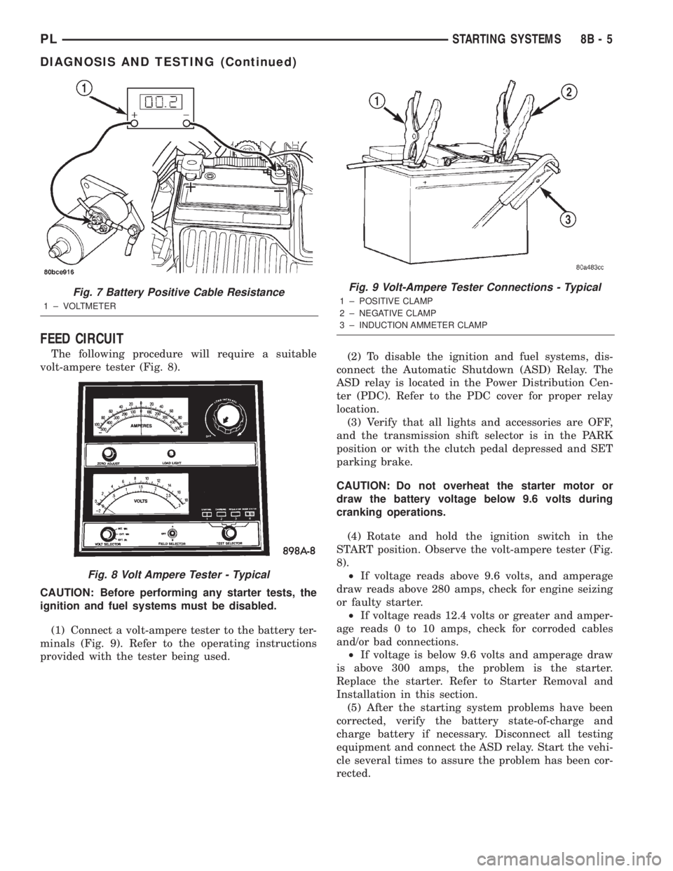
The following procedure will require a suitable
volt-ampere tester (Fig. 8).
CAUTION: Before performing any starter tests, the
ignition and fuel systems must be disabled.
(1) Connect a volt-ampere tester to the battery ter-
minals (Fig. 9). Refer to the operating instructions
provided with the tester being used.(2) To disable the ignition and fuel systems, dis-
connect the Automatic Shutdown (ASD) Relay. The
ASD relay is located in the Power Distribution Cen-
ter (PDC). Refer to the PDC cover for proper relay
location.
(3) Verify that all lights and accessories are OFF,
and the transmission shift selector is in the PARK
position or with the clutch pedal depressed and SET
parking brake.
CAUTION: Do not overheat the starter motor or
draw the battery voltage below 9.6 volts during
cranking operations.
(4) Rotate and hold the ignition switch in the
START position. Observe the volt-ampere tester (Fig.
8).
²If voltage reads above 9.6 volts, and amperage
draw reads above 280 amps, check for engine seizing
or faulty starter.
²If voltage reads 12.4 volts or greater and amper-
age reads 0 to 10 amps, check for corroded cables
and/or bad connections.
²If voltage is below 9.6 volts and amperage draw
is above 300 amps, the problem is the starter.
Replace the starter. Refer to Starter Removal and
Installation in this section.
(5) After the starting system problems have been
corrected, verify the battery state-of-charge and
charge battery if necessary. Disconnect all testing
equipment and connect the ASD relay. Start the vehi-
cle several times to assure the problem has been cor-
rected.
Fig. 7 Battery Positive Cable Resistance
1 ± VOLTMETER
Fig. 8 Volt Ampere Tester - Typical
Fig. 9 Volt-Ampere Tester Connections - Typical
1 ± POSITIVE CLAMP
2 ± NEGATIVE CLAMP
3 ± INDUCTION AMMETER CLAMP
PLSTARTING SYSTEMS 8B - 5
DIAGNOSIS AND TESTING (Continued)
Page 349 of 1285
²Clockspring assembly
²Steering Column Assembly w/Lower Steering
Column Coupler
PASSENGER AIRBAG
After a Passenger Airbag Module has been
deployed, replace the following components because
they cannot be reused.
²Passenger Airbag Module
Inspect all the attaching hardware and instrument
panel for damage. If damage is evident, components
should be replaced.
HANDLING AIRBAG MODULES
DEPLOYED AIRBAG MODULE
The vehicle interior may contain a very small
amount of sodium hydroxide powder, a by-product of
airbag deployment. Sodium hydroxide powder can
irritate the skin, eyes, nose and throat. Wear safety
glasses, rubber gloves, and long sleeved clothing
when cleaning any of the powder residue from the
vehicle.
If you find that the cleanup is irritating your skin,
run cool water over the affected area. Also, if you
experience nasal or throat irritation, exit the vehicle
for fresh air until the irritation ceases. If irritation
continues, see a physician.
UNDEPLOYED AIRBAG MODULE
The airbag modules must be stored in its original
special container until used for service. At no time
should a source of electricity be permitted near the
inflator on the back of an airbag module. When car-
rying or handling an undeployed airbag module, the
trim side of the airbag should be pointing away from
the body to minimize possibility of injury if acciden-
tal deployment occurs. Do not place undeployed air-
bag face down on a solid surface, the airbag will
propel into the air if accidentally deployment occurs.
MAINTENANCE INSPECTION
(1) Check the airbag warning lamp for proper
operation as follows:
(a) Turn ignition switch to the ON position, the
airbag warning lamp should light. If not, test the
system using a DRB llltscan tool and the proper
Body Diagnostic Procedures Manual.
(b) The airbag warning lamp lights, but fails to
go out after eight seconds. Test the system using a
DRB llltscan tool and the proper Body Diagnostic
Procedures Manual.
(c) After correcting active malfunction erase
stored Diagnostic Trouble Codes (DTC's).
REMOVAL AND INSTALLATION
AIRBAG CONTROL MODULE (ACM)
WARNING: THE ACM CONTAINS THE SENSING
ELEMENT AND A SAFING SENSOR WHICH
ENABLES THE SYSTEM TO DEPLOY THE AIR-
BAGS. TO AVOID ACCIDENTAL DEPLOYMENT,
NEVER CONNECT ACM ELECTRICALLY TO THE
SYSTEM WHILE VEHICLE BATTERY IS CON-
NECTED.
DISCONNECT AND ISOLATE THE BATTERY NEG-
ATIVE (GROUND) CABLE BEFORE BEGINNING ANY
AIRBAG SYSTEM COMPONENT REMOVAL OR
INSTALLATION PROCEDURE. THIS WILL DISABLE
THE AIRBAG SYSTEM. FAILURE TO DISCONNECT
BATTERY COULD RESULT IN ACCIDENTAL AIRBAG
DEPLOYMENT AND POSSIBLE PERSONAL INJURY.
ALLOW SYSTEM CAPACITOR TO DISCHARGE
FOR 1 MINUTE BEFORE REMOVING ANY AIRBAG
COMPONENTS.
REMOVAL
(1) Disconnect and isolate the battery negative
cable (Fig. 4).
(2) Remove center console. Refer to Group 23 Body,
Floor Console Removal and Installation.
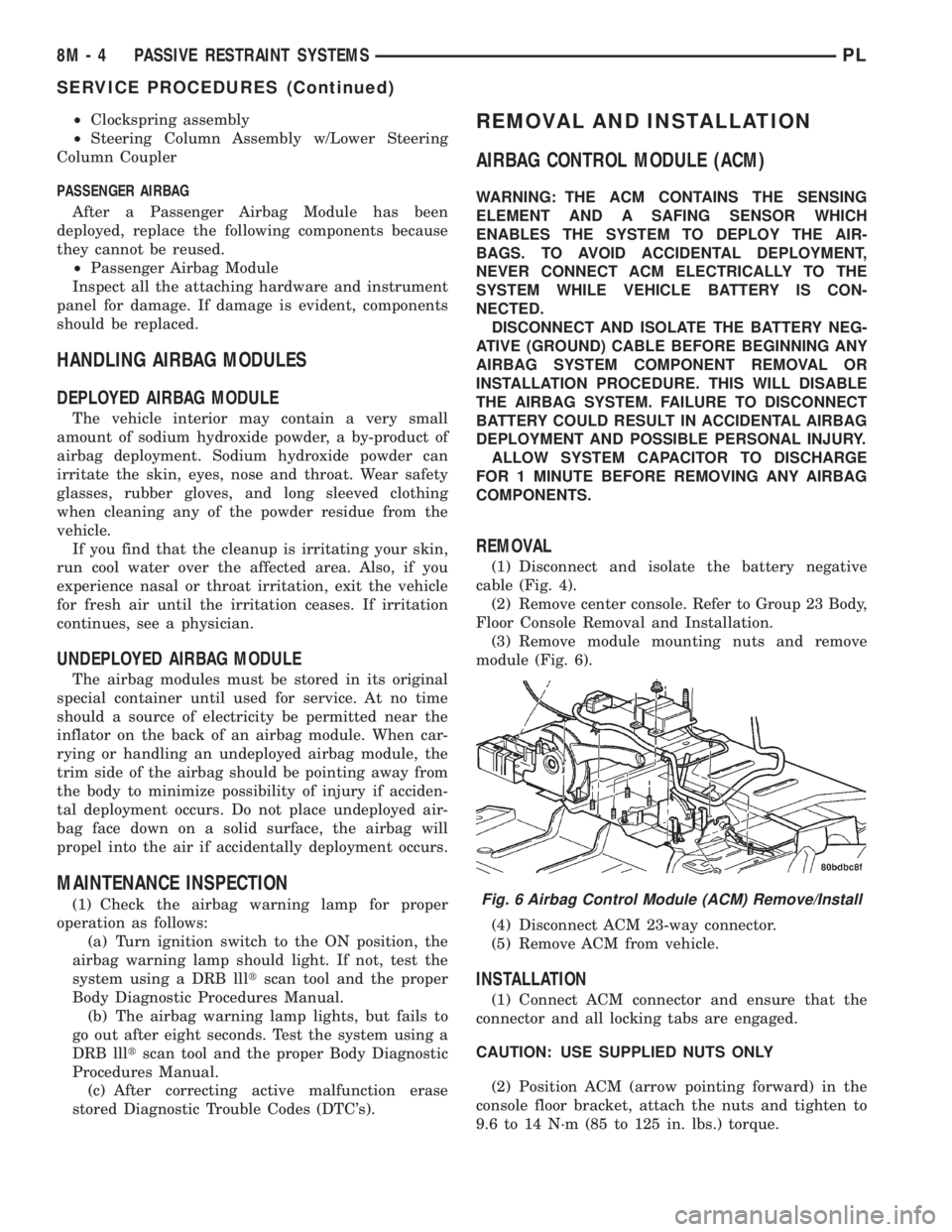
(3) Remove module mounting nuts and remove
module (Fig. 6).
(4) Disconnect ACM 23-way connector.
(5) Remove ACM from vehicle.
INSTALLATION
(1) Connect ACM connector and ensure that the
connector and all locking tabs are engaged.
CAUTION: USE SUPPLIED NUTS ONLY
(2) Position ACM (arrow pointing forward) in the
console floor bracket, attach the nuts and tighten to
9.6 to 14 N´m (85 to 125 in. lbs.) torque.
Fig. 6 Airbag Control Module (ACM) Remove/Install
8M - 4 PASSIVE RESTRAINT SYSTEMSPL
SERVICE PROCEDURES (Continued)
Page 1135 of 1285
DIAGNOSIS AND TESTING
WATER LEAKS
Water leaks can be caused by poor sealing,
improper body component alignment, body seam
porosity, missing plugs, or blocked drain holes. Cen-
trifugal and gravitational force can cause water to
drip from a location away from the actual leak point,
making leak detection difficult. All body sealing
points should be water tight in normal wet-driving
conditions. Water flowing downward from the front of
the vehicle should not enter the passenger or luggage
compartment. Moving sealing surfaces will not
always seal water tight under all conditions. At
times, side glass or door seals will allow water to
enter the passenger compartment during high pres-
sure washing or hard driving rain (severe) condi-
tions. Overcompensating on door or glass
adjustments to stop a water leak that occurs under
severe conditions can cause premature seal wear and
excessive closing or latching effort. After completing
a repair, water-test vehicle to verify leak has stopped
before returning vehicle to use.
VISUAL INSPECTION BEFORE WATER LEAK TESTS
Verify that floor and body plugs are in place, body
drains are clear, and body components are properly
aligned and sealed. If component alignment or seal-
ing is necessary, refer to the appropriate section of
this group for proper procedures.
WATER LEAK TESTS
WARNING: DO NOT USE ELECTRIC SHOP LIGHTS
OR TOOLS IN WATER TEST AREA. PERSONAL
INJURY CAN RESULT.
When the conditions causing a water leak have
been determined, simulate the conditions as closely
as possible.
²If a leak occurs with the vehicle parked in a
steady light rain, flood the leak area with an open-
ended garden hose.
²If a leak occurs while driving at highway speeds
in a steady rain, test the leak area with a reasonable
velocity stream or fan spray of water. Direct the
spray in a direction comparable to actual conditions.
²If a leak occurs when the vehicle is parked on an
incline, hoist the end or side of the vehicle to simu-
late this condition. This method can be used when
the leak occurs when the vehicle accelerates, stops or
turns. If the leak occurs on acceleration, hoist the
front of the vehicle. If the leak occurs when braking,
hoist the back of the vehicle. If the leak occurs on left
turns, hoist the left side of the vehicle. If the leak
occurs on right turns, hoist the right side of the vehi-cle. For hoisting recommendations refer to Group 0,
Lubrication and Maintenance, General Information
section.
WATER LEAK DETECTION
To detect a water leak point-of-entry, do a water
test and watch for water tracks or droplets forming
on the inside of the vehicle. If necessary, remove inte-
rior trim covers or panels to gain visual access to the
leak area. If the hose cannot be positioned without
being held, have someone help do the water test.
Some water leaks must be tested for a considerable
length of time to become apparent. When a leak
appears, find the lowest point of the water track or
drop. After leak point has been found, repair the leak
and water test to verify that the leak has stopped.
Locating the entry point of water that is leaking
into a cavity between panels can be difficult. The
trapped water may splash or run from the cavity,
often at a distance from the entry point. Most water
leaks of this type become apparent after accelerating,
stopping, turning, or when on an incline.
MIRROR INSPECTION METHOD
When a leak point area is visually obstructed, use
a suitable mirror to gain visual access. A mirror can
also be used to deflect light to a limited-access area
to assist in locating a leak point.
BRIGHT LIGHT LEAK TEST METHOD
Some water leaks in the luggage compartment can
be detected without water testing. Position the vehi-
cle in a brightly lit area. From inside the darkened
luggage compartment inspect around seals and body
seams. If necessary, have a helper direct a drop light
over the suspected leak areas around the luggage
compartment. If light is visible through a normally
sealed location, water could enter through the open-
ing.
PRESSURIZED LEAK TEST METHOD
When a water leak into the passenger compart-
ment cannot be detected by water testing, pressurize
the passenger compartment and soap test exterior of
the vehicle. To pressurize the passenger compart-
ment, close all doors and windows, start engine, and
set heater control to high blower in HEAT position. If
engine can not be started, connect a charger to the
battery to ensure adequate voltage to the blower.
With interior pressurized, apply dish detergent solu-
tion to suspected leak area on the exterior of the
vehicle. Apply detergent solution with spray device or
soft bristle brush. If soap bubbles occur at a body
seam, joint, seal or gasket, the leak entry point could
be at that location.
23 - 18 BODYPL