2000 DODGE NEON seat adjustment
[x] Cancel search: seat adjustmentPage 48 of 1285
For more information on the description and oper-
ation of an individual component, refer to the appli-
cable component heading in this section.
STRUT ASSEMBLY (REAR)
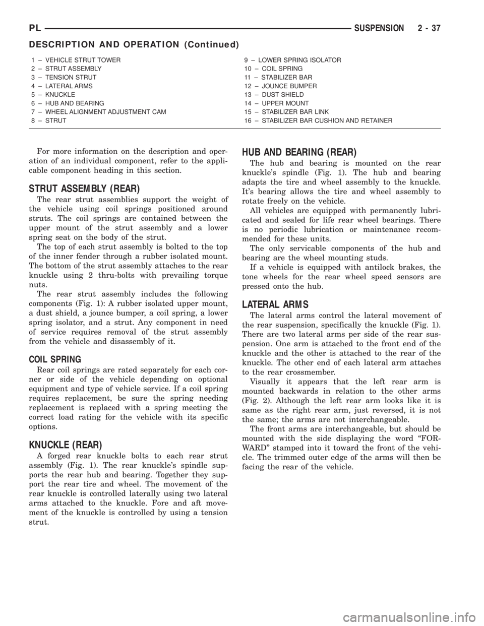
The rear strut assemblies support the weight of
the vehicle using coil springs positioned around
struts. The coil springs are contained between the
upper mount of the strut assembly and a lower
spring seat on the body of the strut.
The top of each strut assembly is bolted to the top
of the inner fender through a rubber isolated mount.
The bottom of the strut assembly attaches to the rear
knuckle using 2 thru-bolts with prevailing torque
nuts.
The rear strut assembly includes the following
components (Fig. 1): A rubber isolated upper mount,
a dust shield, a jounce bumper, a coil spring, a lower
spring isolator, and a strut. Any component in need
of service requires removal of the strut assembly
from the vehicle and disassembly of it.
COIL SPRING
Rear coil springs are rated separately for each cor-
ner or side of the vehicle depending on optional
equipment and type of vehicle service. If a coil spring
requires replacement, be sure the spring needing
replacement is replaced with a spring meeting the
correct load rating for the vehicle with its specific
options.
KNUCKLE (REAR)
A forged rear knuckle bolts to each rear strut
assembly (Fig. 1). The rear knuckle's spindle sup-
ports the rear hub and bearing. Together they sup-
port the rear tire and wheel. The movement of the
rear knuckle is controlled laterally using two lateral
arms attached to the knuckle. Fore and aft move-
ment of the knuckle is controlled by using a tension
strut.
HUB AND BEARING (REAR)
The hub and bearing is mounted on the rear
knuckle's spindle (Fig. 1). The hub and bearing
adapts the tire and wheel assembly to the knuckle.
It's bearing allows the tire and wheel assembly to
rotate freely on the vehicle.
All vehicles are equipped with permanently lubri-
cated and sealed for life rear wheel bearings. There
is no periodic lubrication or maintenance recom-
mended for these units.
The only servicable components of the hub and
bearing are the wheel mounting studs.
If a vehicle is equipped with antilock brakes, the
tone wheels for the rear wheel speed sensors are
pressed onto the hub.
LATERAL ARMS
The lateral arms control the lateral movement of
the rear suspension, specifically the knuckle (Fig. 1).
There are two lateral arms per side of the rear sus-
pension. One arm is attached to the front end of the
knuckle and the other is attached to the rear of the
knuckle. The other end of each lateral arm attaches
to the rear crossmember.
Visually it appears that the left rear arm is
mounted backwards in relation to the other arms
(Fig. 2). Although the left rear arm looks like it is
same as the right rear arm, just reversed, it is not
the same; the arms are not interchangeable.
The front arms are interchangeable, but should be
mounted with the side displaying the word ªFOR-
WARDº stamped into it toward the front of the vehi-
cle. The trimmed outer edge of the arms will then be
facing the rear of the vehicle.
1 ± VEHICLE STRUT TOWER
2 ± STRUT ASSEMBLY
3 ± TENSION STRUT
4 ± LATERAL ARMS
5 ± KNUCKLE
6 ± HUB AND BEARING
7 ± WHEEL ALIGNMENT ADJUSTMENT CAM
8 ± STRUT9 ± LOWER SPRING ISOLATOR
10 ± COIL SPRING
11 ± STABILIZER BAR
12 ± JOUNCE BUMPER
13 ± DUST SHIELD
14 ± UPPER MOUNT
15 ± STABILIZER BAR LINK
16 ± STABILIZER BAR CUSHION AND RETAINER
PLSUSPENSION 2 - 37
DESCRIPTION AND OPERATION (Continued)
Page 86 of 1285
The adapter is used to mount the brake caliper to the
vehicle (Fig. 9). The adapter has two machined abut-
ments, which are used to position and align the cal-
iper and brake pads for movement inboard and
outboard. The adapter also mounts the parking brake
shoes and actuating cables to the vehicle.
PARKING BRAKES
The parking brakes (Fig. 4) consist of the following
components:
²Hand-operated park brake lever - automatic-ad-
justing
²Parking brake cables
²Actuation levers and struts
²Duo-servo parking brake assembly (rear disc
only)
PARKING BRAKE LEVER
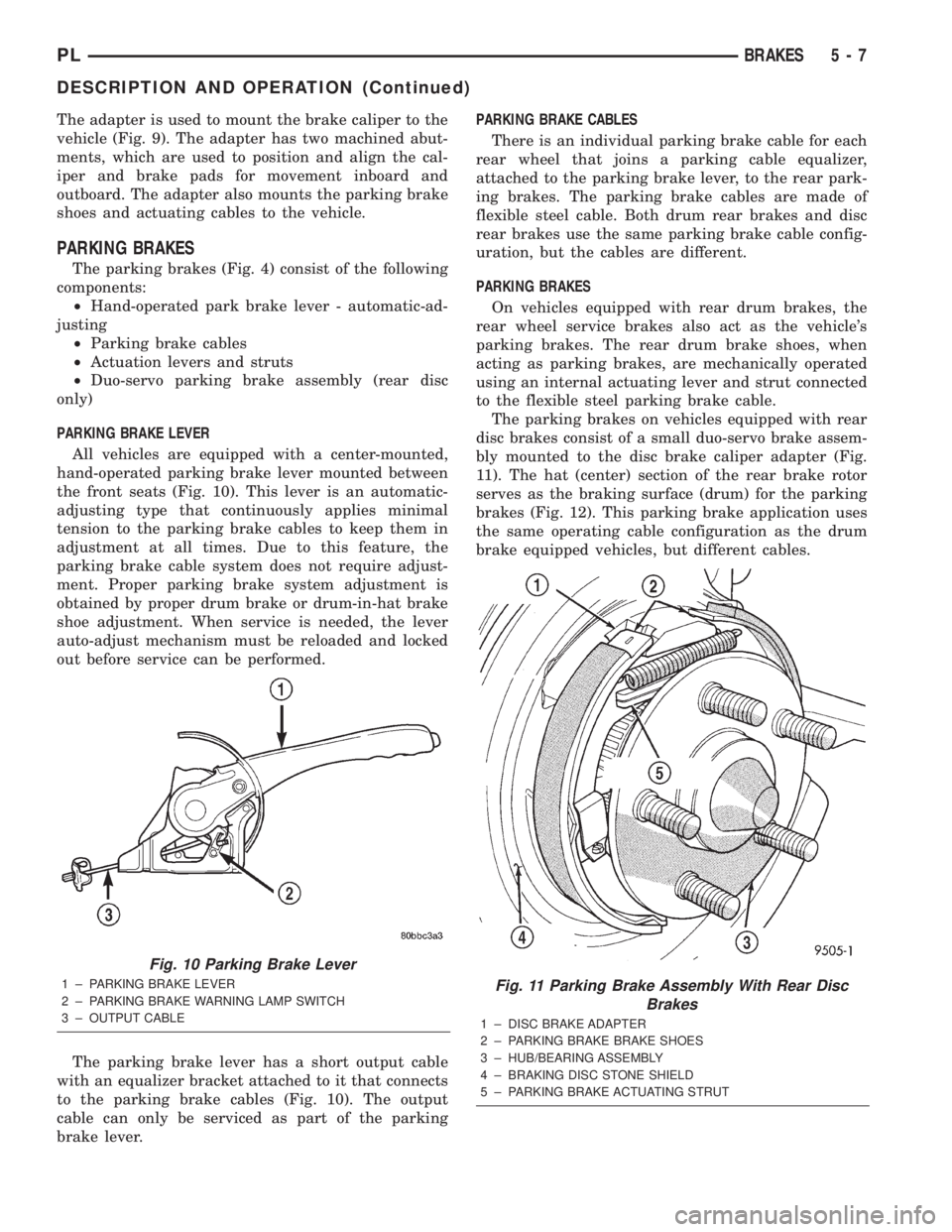
All vehicles are equipped with a center-mounted,
hand-operated parking brake lever mounted between
the front seats (Fig. 10). This lever is an automatic-
adjusting type that continuously applies minimal
tension to the parking brake cables to keep them in
adjustment at all times. Due to this feature, the
parking brake cable system does not require adjust-
ment. Proper parking brake system adjustment is
obtained by proper drum brake or drum-in-hat brake
shoe adjustment. When service is needed, the lever
auto-adjust mechanism must be reloaded and locked
out before service can be performed.
The parking brake lever has a short output cable
with an equalizer bracket attached to it that connects
to the parking brake cables (Fig. 10). The output
cable can only be serviced as part of the parking
brake lever.PARKING BRAKE CABLES
There is an individual parking brake cable for each
rear wheel that joins a parking cable equalizer,
attached to the parking brake lever, to the rear park-
ing brakes. The parking brake cables are made of
flexible steel cable. Both drum rear brakes and disc
rear brakes use the same parking brake cable config-
uration, but the cables are different.
PARKING BRAKES
On vehicles equipped with rear drum brakes, the
rear wheel service brakes also act as the vehicle's
parking brakes. The rear drum brake shoes, when
acting as parking brakes, are mechanically operated
using an internal actuating lever and strut connected
to the flexible steel parking brake cable.
The parking brakes on vehicles equipped with rear
disc brakes consist of a small duo-servo brake assem-
bly mounted to the disc brake caliper adapter (Fig.
11). The hat (center) section of the rear brake rotor
serves as the braking surface (drum) for the parking
brakes (Fig. 12). This parking brake application uses
the same operating cable configuration as the drum
brake equipped vehicles, but different cables.
Fig. 10 Parking Brake Lever
1 ± PARKING BRAKE LEVER
2 ± PARKING BRAKE WARNING LAMP SWITCH
3 ± OUTPUT CABLEFig. 11 Parking Brake Assembly With Rear Disc
Brakes
1 ± DISC BRAKE ADAPTER
2 ± PARKING BRAKE BRAKE SHOES
3 ± HUB/BEARING ASSEMBLY
4 ± BRAKING DISC STONE SHIELD
5 ± PARKING BRAKE ACTUATING STRUT
PLBRAKES 5 - 7
DESCRIPTION AND OPERATION (Continued)
Page 104 of 1285
(10) If the vehicle is equipped with antilock
brakes, carefully push the power brake booster for-
ward until the booster contacts the ABS ICU mount-
ing bracket.
(11) If the vehicle does not have antilock brakes,
carefully push the power brake booster forward one
to two inches being careful not to stretch the brake
lines from the master cylinder to the brakes.
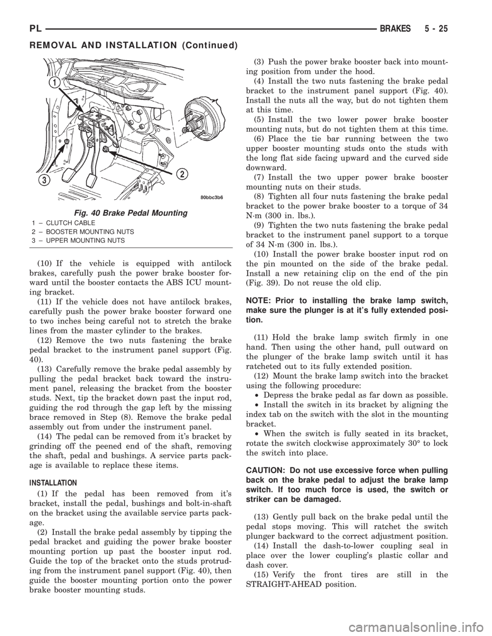
(12) Remove the two nuts fastening the brake
pedal bracket to the instrument panel support (Fig.
40).
(13) Carefully remove the brake pedal assembly by
pulling the pedal bracket back toward the instru-
ment panel, releasing the bracket from the booster
studs. Next, tip the bracket down past the input rod,
guiding the rod through the gap left by the missing
brace removed in Step (8). Remove the brake pedal
assembly out from under the instrument panel.
(14) The pedal can be removed from it's bracket by
grinding off the peened end of the shaft, removing
the shaft, pedal and bushings. A service parts pack-
age is available to replace these items.
INSTALLATION
(1) If the pedal has been removed from it's
bracket, install the pedal, bushings and bolt-in-shaft
on the bracket using the available service parts pack-
age.
(2) Install the brake pedal assembly by tipping the
pedal bracket and guiding the power brake booster
mounting portion up past the booster input rod.
Guide the top of the bracket onto the studs protrud-
ing from the instrument panel support (Fig. 40), then
guide the booster mounting portion onto the power
brake booster mounting studs.(3) Push the power brake booster back into mount-
ing position from under the hood.
(4) Install the two nuts fastening the brake pedal
bracket to the instrument panel support (Fig. 40).
Install the nuts all the way, but do not tighten them
at this time.
(5) Install the two lower power brake booster
mounting nuts, but do not tighten them at this time.
(6) Place the tie bar running between the two
upper booster mounting studs onto the studs with
the long flat side facing upward and the curved side
downward.
(7) Install the two upper power brake booster
mounting nuts on their studs.
(8) Tighten all four nuts fastening the brake pedal
bracket to the power brake booster to a torque of 34
N´m (300 in. lbs.).
(9) Tighten the two nuts fastening the brake pedal
bracket to the instrument panel support to a torque
of 34 N´m (300 in. lbs.).
(10) Install the power brake booster input rod on
the pin mounted on the side of the brake pedal.
Install a new retaining clip on the end of the pin
(Fig. 39). Do not reuse the old clip.
NOTE: Prior to installing the brake lamp switch,
make sure the plunger is at it's fully extended posi-
tion.
(11) Hold the brake lamp switch firmly in one
hand. Then using the other hand, pull outward on
the plunger of the brake lamp switch until it has
ratcheted out to its fully extended position.
(12) Mount the brake lamp switch into the bracket
using the following procedure:
²Depress the brake pedal as far down as possible.
²Install the switch in its bracket by aligning the
index tab on the switch with the slot in the mounting
bracket.
²When the switch is fully seated in its bracket,
rotate the switch clockwise approximately 30É to lock
the switch into place.
CAUTION: Do not use excessive force when pulling
back on the brake pedal to adjust the brake lamp
switch. If too much force is used, the switch or
striker can be damaged.
(13) Gently pull back on the brake pedal until the
pedal stops moving. This will ratchet the switch
plunger backward to the correct adjustment position.
(14) Install the dash-to-lower coupling seal in
place over the lower coupling's plastic collar and
dash cover.
(15) Verify the front tires are still in the
STRAIGHT-AHEAD position.
Fig. 40 Brake Pedal Mounting
1 ± CLUTCH CABLE
2 ± BOOSTER MOUNTING NUTS
3 ± UPPER MOUNTING NUTS
PLBRAKES 5 - 25
REMOVAL AND INSTALLATION (Continued)
Page 106 of 1285
(4) Install the power brake booster mounting nuts.
Tighten the four nuts fastening the brake pedal
bracket to the power brake booster to a torque of 34
N´m (300 in. lbs.).
(5) Tighten the two nuts fastening the brake pedal
bracket to the instrument panel support to a torque
of 34 N´m (300 in. lbs.).
(6) Connect the clutch cable to the clutch pedal
spacer on the pedal (Fig. 41).
(7) Connect the wiring harness connector going to
the clutch pedal switches (Fig. 42).
(8) Install the power brake booster input rod on
the pin mounted on the side of the brake pedal.
Install a new retaining clip on the end of the pin
(Fig. 39). Do not reuse the old clip.
NOTE: Prior to installing the brake lamp switch,
make sure the plunger is at it's fully extended posi-
tion.
(9) Hold the brake lamp switch firmly in one hand.
Then using the other hand, pull outward on the
plunger of the brake lamp switch until it has ratch-
eted out to its fully extended position.
(10) Mount the brake lamp switch into the bracket
using the following procedure:
²Depress the brake pedal as far down as possible.
²Install the switch in its bracket by aligning the
index tab on the switch with the slot in the mounting
bracket.
²When the switch is fully seated in its bracket,
rotate the switch clockwise approximately 30É to lock
the switch into place.
CAUTION: Do not use excessive force when pulling
back on the brake pedal to adjust the brake lamp
switch. If too much force is used, the switch or
striker can be damaged.
(11) Gently pull back on the brake pedal until the
pedal stops moving. This will ratchet the switch
plunger backward to the correct adjustment position.
(12) Install the instrument panel. Refer to the
INSTRUMENT PANELS AND SYSTEMS group in
this service manual for the required procedure.
(13) Check the stop lamps to verify they are oper-
ating properly and not staying on when the pedal is
in the released position.
(14) Road test the vehicle to ensure proper opera-
tion of the brakes.
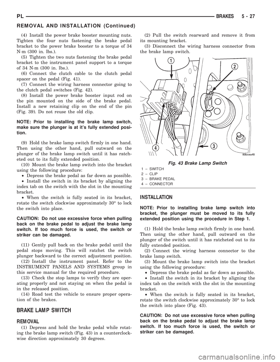
BRAKE LAMP SWITCH
REMOVAL
(1) Depress and hold the brake pedal while rotat-
ing the brake lamp switch (Fig. 43) in a counterclock-
wise direction approximately 30 degrees.(2) Pull the switch rearward and remove it from
its mounting bracket.
(3) Disconnect the wiring harness connector from
the brake lamp switch.
INSTALLATION
NOTE: Prior to installing brake lamp switch into
bracket, the plunger must be moved to its fully
extended position using the procedure in Step 1.
(1) Hold the brake lamp switch firmly in one hand.
Then using the other hand, pull outward on the
plunger of the switch until it has ratcheted out to its
fully extended position.
(2) Connect the wiring harness connector to the
brake lamp switch.
(3) Mount the brake lamp switch into the bracket
using the following procedure:
²Depress the brake pedal as far down as possible.
²Install the switch in its bracket by aligning the
index tab on the switch with the slot in the mounting
bracket.
²When the switch is fully seated in its bracket,
rotate the switch clockwise approximately 30É to lock
the switch into place (Fig. 43).
CAUTION: Do not use excessive force when pulling
back on the brake pedal to adjust the brake lamp
switch. If too much force is used, the switch or
striker can be damaged.
Fig. 43 Brake Lamp Switch
1 ± SWITCH
2 ± CLIP
3 ± BRAKE PEDAL
4 ± CONNECTOR
PLBRAKES 5 - 27
REMOVAL AND INSTALLATION (Continued)
Page 120 of 1285
(6) Lubricate both adapter caliper slide abutments
with a liberal amount of MopartMultipurpose Lubri-
cant, or an equivalent.
CAUTION: Use care when installing the caliper
assembly onto adapter so the guide pin bushings
and sleeves do not get damaged by the mounting
bosses on adapter.
(7) Starting with the lower end, carefully lower the
caliper and brake shoes over the brake rotor and
catch the caliper's bottom edge behind the caliper
slide abutment (Fig. 71). Rotate the top of the caliper
into mounting position on the adapter.
CAUTION: Extreme caution should be taken not to
cross thread the caliper guide pin bolts when they
are installed.
(8) Carefully install the caliper guide pin bolts
(Fig. 70), then tighten them to a torque of 22 N´m
(192 in. lbs.).
(9) Install the tire and wheel assembly. Tighten
the wheel mounting nuts to a torque of 135 N´m (100
ft. lbs.).
(10) Repeat the above procedure to the rear brakes
on the other side of the vehicle.
(11) Lower the vehicle.
(12) Pump the brake pedal several times to ensure
the vehicle has a firm brake pedal before moving the
vehicle.(13) Road test the vehicle and make several stops
to wear off any foreign material on the brakes and to
seat the brake shoes.
BRAKE ROTOR (REAR)
REMOVAL
(1) Raise the vehicle. Refer to HOISTING in the
LUBRICATION AND MAINTENANCE group for the
proper lifting procedure.
(2) Remove the rear tire and wheel assembly.
(3) Remove the rear disc brake caliper assembly
from the brake rotor and store it out of the way.
Refer to DISC BRAKE SHOES (REAR) in this
REMOVAL AND INSTALLATION section of this ser-
vice manual group.
(4) Remove any clips retaining the brake rotor
(Fig. 70).
(5) Remove the brake rotor by pulling it straight
off the wheel mounting studs.
INSTALLATION
NOTE: Inspect the disc brake shoes and parking
brake shoes before brake rotor installation.
(1) Install the rear brake rotor over the wheel
mounting studs and onto the hub (Fig. 70).
(2) Install rear disc brake caliper. Refer to DISC
BRAKE SHOES (REAR) in this REMOVAL AND
INSTALLATION section of this service manual
group.
(3) Install the tire and wheel assembly. Tighten
the wheel mounting nuts to a torque of 135 N´m (100
ft. lbs.).
(4) Adjust the parking brake shoes as necessary.
Refer to ADJUSTMENTS in this section of this ser-
vice manual group.
(5) Lower the vehicle.
(6) Pump the brake pedal before moving the vehi-
cle to set the brake shoes to the brake rotor.
DRUM BRAKE WHEEL CYLINDER (REAR)
NOTE: Before proceeding with this procedure,
review SERVICE WARNINGS AND CAUTIONS at the
beginning of REMOVAL AND INSTALLATION in this
section.
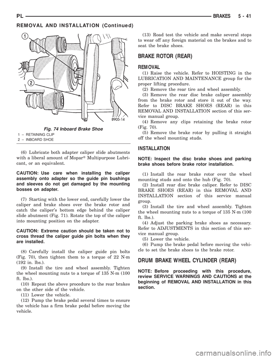
Fig. 74 Inboard Brake Shoe
1 ± RETAINING CLIP
2 ± INBOARD SHOE
PLBRAKES 5 - 41
REMOVAL AND INSTALLATION (Continued)
Page 125 of 1285
(4) Remove the brake drum (Fig. 87).
NOTE: If the drum does not come off, further brake
clearance can be obtained by backing off the brake
automatic adjuster screw. Remove the rubber plug
from the top of brake support plate. Rotate the
automatic adjuster screw in an upward motion,
using a screwdriver.
INSTALLATION
NOTE: Before installing the drum, inspect the brake
shoe linings for wear, shoe alignment, and contam-
ination.
(1) Install the rear brake drum on rear hub and
bearing (Fig. 87).
(2) Install the tire and wheel assembly. Tighten
the wheel mounting nuts to a torque of 135 N´m (100
ft. lbs.).
(3) Adjust the rear brake shoes as necessary. Refer
to ADJUSTMENTS in this section of this service
manual group.
(4) Lower the vehicle.
DRUM BRAKE SHOE SUPPORT PLATE (REAR)
NOTE: Before proceeding with this procedure,
review SERVICE WARNINGS AND CAUTIONS at the
beginning of REMOVAL AND INSTALLATION in this
section.
REMOVAL
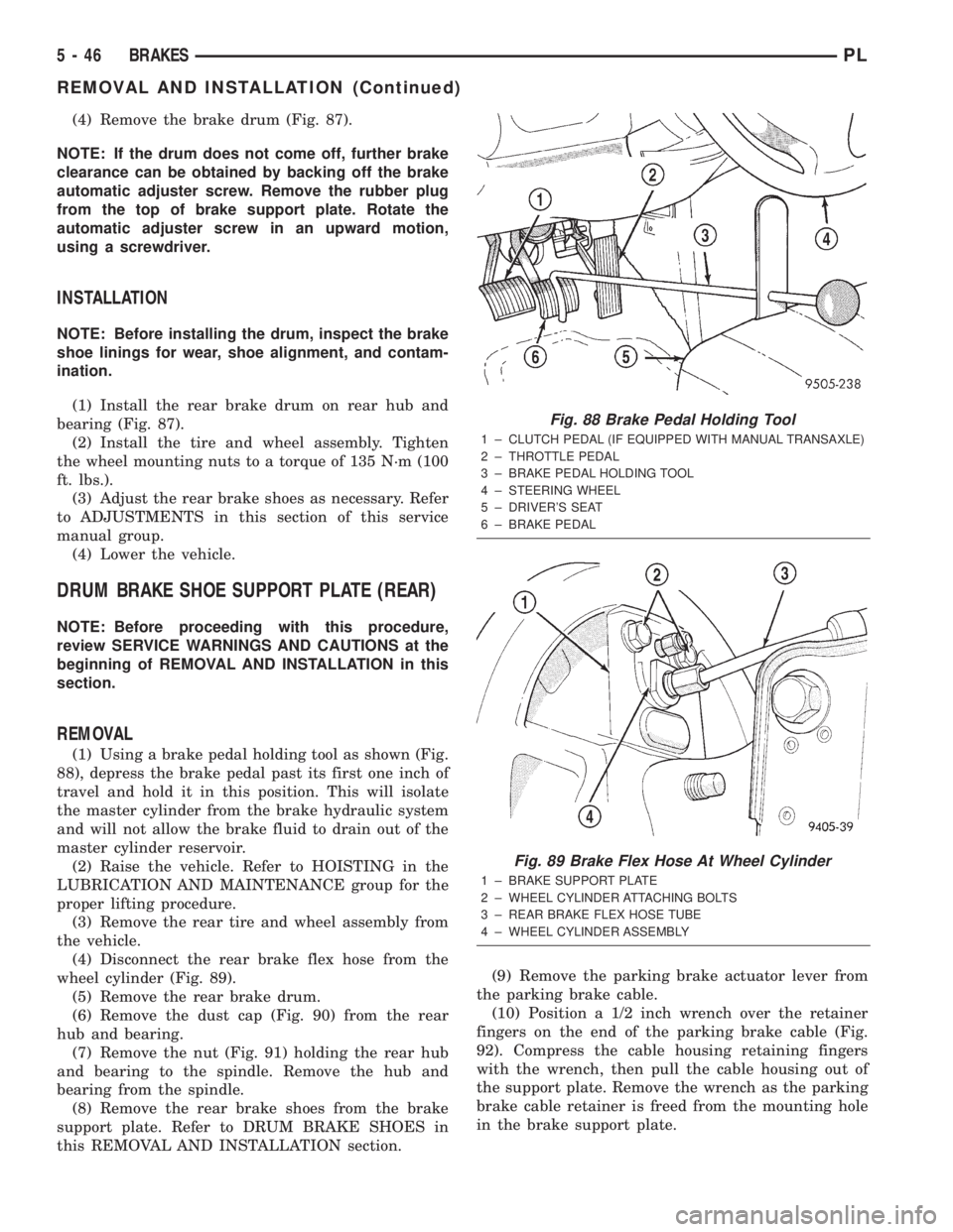
(1) Using a brake pedal holding tool as shown (Fig.
88), depress the brake pedal past its first one inch of
travel and hold it in this position. This will isolate
the master cylinder from the brake hydraulic system
and will not allow the brake fluid to drain out of the
master cylinder reservoir.
(2) Raise the vehicle. Refer to HOISTING in the
LUBRICATION AND MAINTENANCE group for the
proper lifting procedure.
(3) Remove the rear tire and wheel assembly from
the vehicle.
(4) Disconnect the rear brake flex hose from the
wheel cylinder (Fig. 89).
(5) Remove the rear brake drum.
(6) Remove the dust cap (Fig. 90) from the rear
hub and bearing.
(7) Remove the nut (Fig. 91) holding the rear hub
and bearing to the spindle. Remove the hub and
bearing from the spindle.
(8) Remove the rear brake shoes from the brake
support plate. Refer to DRUM BRAKE SHOES in
this REMOVAL AND INSTALLATION section.(9) Remove the parking brake actuator lever from
the parking brake cable.
(10) Position a 1/2 inch wrench over the retainer
fingers on the end of the parking brake cable (Fig.
92). Compress the cable housing retaining fingers
with the wrench, then pull the cable housing out of
the support plate. Remove the wrench as the parking
brake cable retainer is freed from the mounting hole
in the brake support plate.
Fig. 88 Brake Pedal Holding Tool
1 ± CLUTCH PEDAL (IF EQUIPPED WITH MANUAL TRANSAXLE)
2 ± THROTTLE PEDAL
3 ± BRAKE PEDAL HOLDING TOOL
4 ± STEERING WHEEL
5 ± DRIVER'S SEAT
6 ± BRAKE PEDAL
Fig. 89 Brake Flex Hose At Wheel Cylinder
1 ± BRAKE SUPPORT PLATE
2 ± WHEEL CYLINDER ATTACHING BOLTS
3 ± REAR BRAKE FLEX HOSE TUBE
4 ± WHEEL CYLINDER ASSEMBLY
5 - 46 BRAKESPL
REMOVAL AND INSTALLATION (Continued)
Page 128 of 1285
INSTALLATION
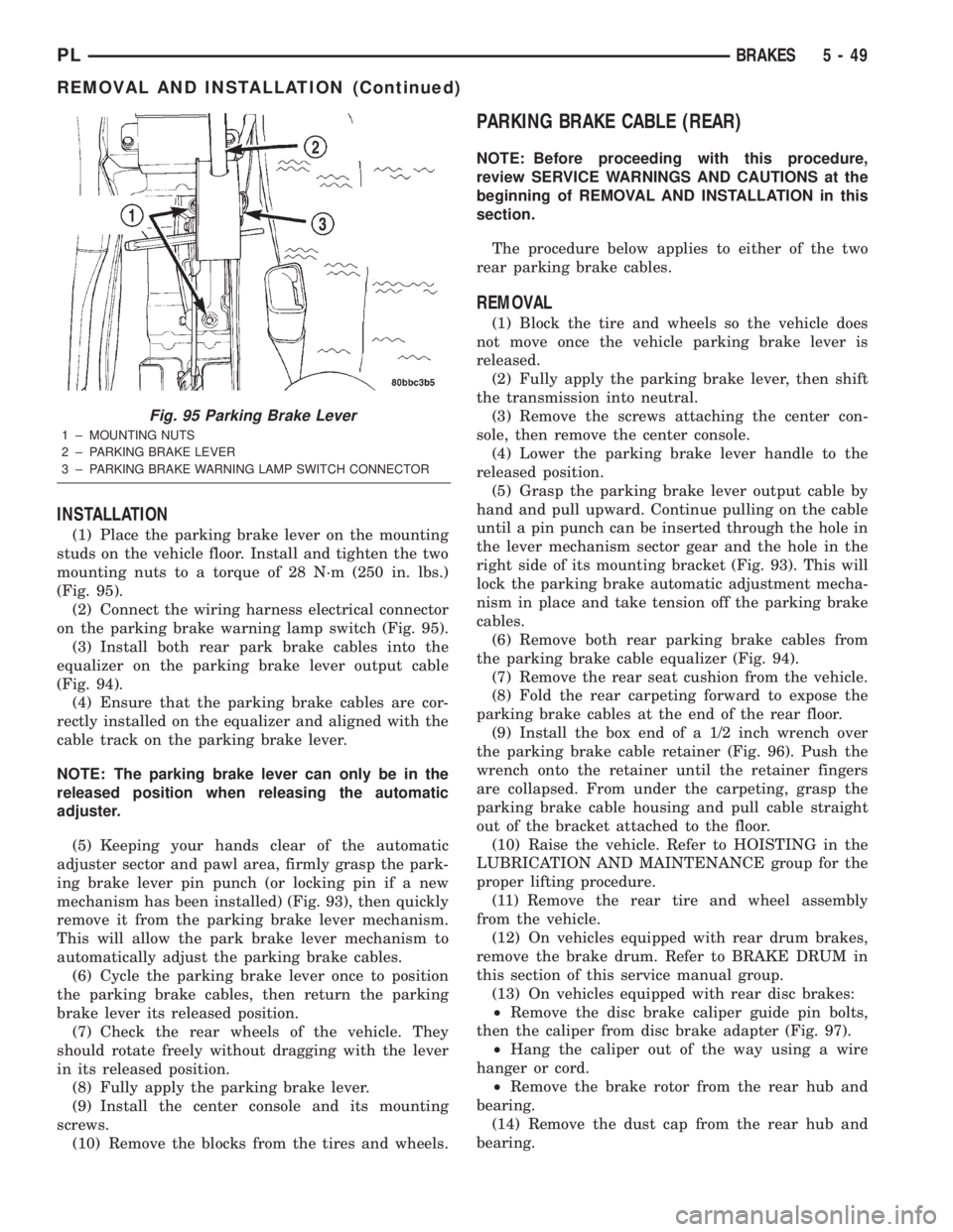
(1) Place the parking brake lever on the mounting
studs on the vehicle floor. Install and tighten the two
mounting nuts to a torque of 28 N´m (250 in. lbs.)
(Fig. 95).
(2) Connect the wiring harness electrical connector
on the parking brake warning lamp switch (Fig. 95).
(3) Install both rear park brake cables into the
equalizer on the parking brake lever output cable
(Fig. 94).
(4) Ensure that the parking brake cables are cor-
rectly installed on the equalizer and aligned with the
cable track on the parking brake lever.
NOTE: The parking brake lever can only be in the
released position when releasing the automatic
adjuster.
(5) Keeping your hands clear of the automatic
adjuster sector and pawl area, firmly grasp the park-
ing brake lever pin punch (or locking pin if a new
mechanism has been installed) (Fig. 93), then quickly
remove it from the parking brake lever mechanism.
This will allow the park brake lever mechanism to
automatically adjust the parking brake cables.
(6) Cycle the parking brake lever once to position
the parking brake cables, then return the parking
brake lever its released position.
(7) Check the rear wheels of the vehicle. They
should rotate freely without dragging with the lever
in its released position.
(8) Fully apply the parking brake lever.
(9) Install the center console and its mounting
screws.
(10) Remove the blocks from the tires and wheels.
PARKING BRAKE CABLE (REAR)
NOTE: Before proceeding with this procedure,
review SERVICE WARNINGS AND CAUTIONS at the
beginning of REMOVAL AND INSTALLATION in this
section.
The procedure below applies to either of the two
rear parking brake cables.
REMOVAL
(1) Block the tire and wheels so the vehicle does
not move once the vehicle parking brake lever is
released.
(2) Fully apply the parking brake lever, then shift
the transmission into neutral.
(3) Remove the screws attaching the center con-
sole, then remove the center console.
(4) Lower the parking brake lever handle to the
released position.
(5) Grasp the parking brake lever output cable by
hand and pull upward. Continue pulling on the cable
until a pin punch can be inserted through the hole in
the lever mechanism sector gear and the hole in the
right side of its mounting bracket (Fig. 93). This will
lock the parking brake automatic adjustment mecha-
nism in place and take tension off the parking brake
cables.
(6) Remove both rear parking brake cables from
the parking brake cable equalizer (Fig. 94).
(7) Remove the rear seat cushion from the vehicle.
(8) Fold the rear carpeting forward to expose the
parking brake cables at the end of the rear floor.
(9) Install the box end of a 1/2 inch wrench over
the parking brake cable retainer (Fig. 96). Push the
wrench onto the retainer until the retainer fingers
are collapsed. From under the carpeting, grasp the
parking brake cable housing and pull cable straight
out of the bracket attached to the floor.
(10) Raise the vehicle. Refer to HOISTING in the
LUBRICATION AND MAINTENANCE group for the
proper lifting procedure.
(11) Remove the rear tire and wheel assembly
from the vehicle.
(12) On vehicles equipped with rear drum brakes,
remove the brake drum. Refer to BRAKE DRUM in
this section of this service manual group.
(13) On vehicles equipped with rear disc brakes:
²Remove the disc brake caliper guide pin bolts,
then the caliper from disc brake adapter (Fig. 97).
²Hang the caliper out of the way using a wire
hanger or cord.
²Remove the brake rotor from the rear hub and
bearing.
(14) Remove the dust cap from the rear hub and
bearing.
Fig. 95 Parking Brake Lever
1 ± MOUNTING NUTS
2 ± PARKING BRAKE LEVER
3 ± PARKING BRAKE WARNING LAMP SWITCH CONNECTOR
PLBRAKES 5 - 49
REMOVAL AND INSTALLATION (Continued)
Page 131 of 1285
(3) Install the parking brake cable into the brake
support plate or the rear disc brake adapter. Be sure
the locking fingers on the cable retainer are
expanded once the cable is pushed all the way into
the support plate or brake adapter hole to ensure the
cable is securely held in place.
(4) On vehicles equipped with rear drum brakes:
²Install the parking brake cable on the parking
brake cable actuating lever (Fig. 99).
²Install the actuating spring to the brake shoe
and the brake adjustment lever (Fig. 100).
(5) On vehicles equipped with rear disc brakes:²Install the parking brake shoes actuator lever on
the parking brake cable (Fig. 102).
²Install the parking brake shoe assemblies on the
disc brake adapter (Fig. 98).
(6) Install the hub and bearing on the rear spin-
dle. Install a new hub and bearing retaining nut.
Tighten the retaining nut to a torque of 217 N´m
(160 ft. lbs.).
(7) Install the hub and bearing dust cap.
(8) On drum brake equipped vehicles, install the
rear brake drum.
(9) On vehicles equipped with rear disc brakes,
install the brake rotor, then the disc brake caliper
(Fig. 97). Install the two caliper guide pin bolts, then
tighten them to a torque of 22 N´m (192 in. lbs.).
(10) Install the rear tire and wheel assembly.
Tighten all wheel nuts to a torque of 135 N´m (100 ft.
lbs.).
(11) Lower the vehicle.
(12) Ensure that the seal grommet on the cable
that was installed from underneath is fully seated
into the floor pan.
(13) Route the parking brake cable under the car-
peting, up to parking brake cable retaining bracket
on floor pan. Install the parking brake cable through
the retaining bracket. Push the cable in until the
locking fingers on the cable retainer lock the cable
into place.
(14) Install the rear parking brake cables into the
equalizer on the parking brake lever output cable
(Fig. 94).
(15) Ensure that the parking brake cables are cor-
rectly installed on the equalizer and aligned with the
cable track on the parking brake lever.
NOTE: The parking brake lever can be in any posi-
tion when releasing the automatic adjuster.
(16) Keeping your hands clear of the automatic
adjuster sector and pawl area, firmly grasp the park-
ing brake lever pin punch (or locking pin if a new
mechanism has been installed) (Fig. 93), then quickly
remove it from the parking brake lever mechanism.
This will allow the park brake lever mechanism to
automatically adjust the parking brake cables.
(17) Cycle the parking brake lever once to position
the parking brake cables, then return the parking
brake lever its released position.
(18) Check the rear wheels of the vehicle. They
should rotate freely without dragging with the lever
in its released position.
(19) Reposition the rear carpeting into place.
(20) Install the rear seat cushion. Be sure the seat
cushion is fully installed in the retainers on the floor
pan of the vehicle.
(21) Fully apply the parking brake lever.
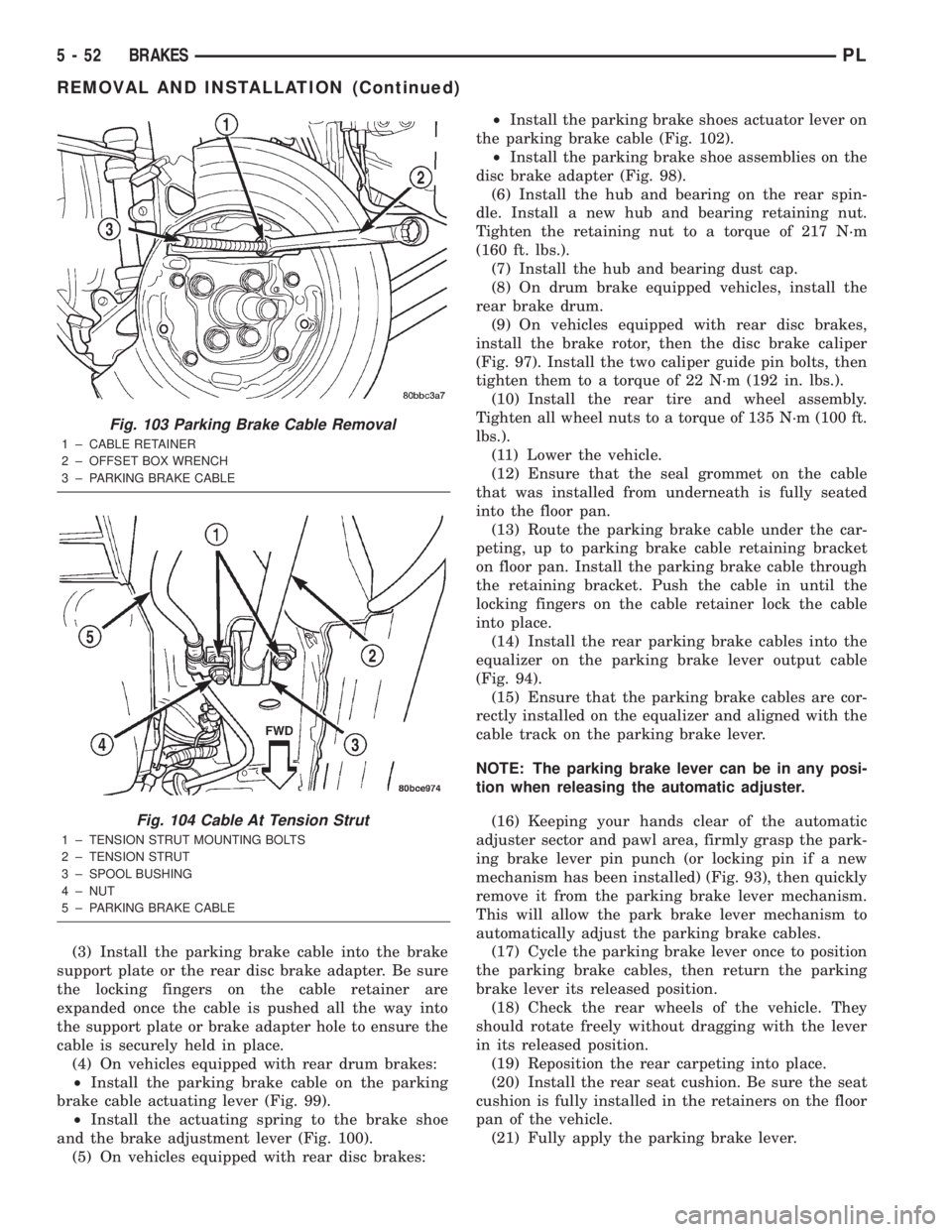
Fig. 103 Parking Brake Cable Removal
1 ± CABLE RETAINER
2 ± OFFSET BOX WRENCH
3 ± PARKING BRAKE CABLE
Fig. 104 Cable At Tension Strut
1 ± TENSION STRUT MOUNTING BOLTS
2 ± TENSION STRUT
3 ± SPOOL BUSHING
4 ± NUT
5 ± PARKING BRAKE CABLE
5 - 52 BRAKESPL
REMOVAL AND INSTALLATION (Continued)