2000 DODGE NEON turn signal
[x] Cancel search: turn signalPage 1 of 1285

GROUP TAB LOCATORINIntroductionINaIntroduction0Lubrication and Maintenance2Suspension3Differential and Driveline5Brakes6Clutch7Cooling8ABattery8BStarting8CCharging System8DIgnition System8EInstrument Panel and Systems8EaInstrument Panel and Systems8FAudio System8GHorns8HVehicle Speed Control System8JTurn Signal and Flashers8KWindshield Wipers and Washers8LLamps8LaLamps8MRestraint System8NElectrically Heated Systems8OPower Distribution Systems8PPower Door Locks8QImmobilizer System8SPower Windows8TPower Mirrors8TaPower Mirrors8UChime Warning/Reminder System8WWiring Diagrams - LHD and RHD9Engine11Exhaust System13Frame and Bumpers14Fuel System19Steering21Transaxle22Tires and Wheels23Body24Heating and Air Conditioning24aHeating and Air Conditioning25Emission Control Systems
Page 146 of 1285
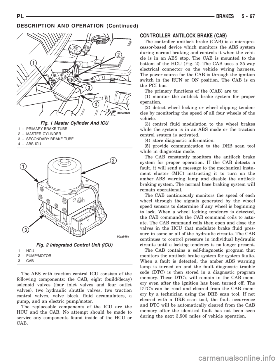
The ABS with traction control ICU consists of the
following components: the CAB, eight (build/decay)
solenoid valves (four inlet valves and four outlet
valves), two hydraulic shuttle valves, two traction
control valves, valve block, fluid accumulators, a
pump, and an electric pump/motor.
The replaceable components of the ICU are the
HCU and the CAB. No attempt should be made to
service any components found inside of the HCU or
CAB.
CONTROLLER ANTILOCK BRAKE (CAB)
The controller antilock brake (CAB) is a micropro-
cessor-based device which monitors the ABS system
during normal braking and controls it when the vehi-
cle is in an ABS stop. The CAB is mounted to the
bottom of the HCU (Fig. 2). The CAB uses a 25-way
electrical connector on the vehicle wiring harness.
The power source for the CAB is through the ignition
switch in the RUN or ON position. The CAB is on
the PCI bus.
The primary functions of the (CAB) are to:
(1) monitor the antilock brake system for proper
operation.
(2) detect wheel locking or wheel slipping tenden-
cies by monitoring the speed of all four wheels of the
vehicle.
(3) control fluid modulation to the wheel brakes
while the system is in an ABS mode or the traction
control system is activated.
(4) store diagnostic information.
(5) provide communication to the DRB scan tool
while in diagnostic mode.
The CAB constantly monitors the antilock brake
system for proper operation. If the CAB detects a
fault, it will send a message to the mechanical instu-
ment cluster (MIC) instructing it to turn on the
amber ABS warning lamp and disable the antilock
braking system. The normal base braking system will
remain operational.
The CAB continuously monitors the speed of each
wheel through the signals generated by the wheel
speed sensors to determine if any wheel is beginning
to lock. When a wheel locking tendency is detected,
the CAB commands the CAB command coils to actu-
ate. The CAB command coils then open and close the
valves in the HCU that modulate brake fluid pres-
sure in some or all of the hydraulic circuits. The CAB
continues to control pressure in individual hydraulic
circuits until a locking tendency is no longer present.
The CAB contains a self-diagnostic program that
monitors the antilock brake system for system faults.
When a fault is detected, the amber ABS warning
lamp is turned on and the fault diagnostic trouble
code (DTC) is then stored in a diagnostic program
memory. These DTC's will remain in the CAB mem-
ory even after the ignition has been turned off. The
DTC's can be read and cleared from the CAB mem-
ory by a technician using the DRB scan tool. If not
cleared with a DRB scan tool, the fault occurrence
and DTC will be automatically cleared from the CAB
memory after the identical fault has not been seen
during the next 3,500 miles of vehicle operation.
Fig. 1 Master Cylinder And ICU
1 ± PRIMARY BRAKE TUBE
2 ± MASTER CYLINDER
3 ± SECONDARY BRAKE TUBE
4 ± ABS ICU
Fig. 2 Integrated Control Unit (ICU)
1 ± HCU
2 ± PUMP/MOTOR
3 ± CAB
PLBRAKES 5 - 67
DESCRIPTION AND OPERATION (Continued)
Page 148 of 1285
AMBER ABS WARNING LAMP
The amber ABS warning lamp is located in the
instrument cluster. The purpose of the warning lamp
is discussed in detail below.
When the ignition key is turned to the ON posi-
tion, the amber ABS warning lamp is lit until the
CAB completes its self-tests and turns off the lamp
(approximately 4 seconds). The amber ABS warning
lamp will illuminate when the CAB detects a condi-
tion that results in the shutdown of ABS function.
The CAB sends a message to the mechanical instu-
ment cluster (MIC) instructing it to turn on the
amber ABS warning lamp.
Under most conditions, when the amber ABS warn-
ing lamp is on, only the ABS function of the brake
system is affected; The electronic brake distribution
(EBD), the base brake system and the ability to stop
the vehicle are not affected.
WHEEL SPEED SENSOR (WSS)
At each wheel of the vehicle there is one wheel
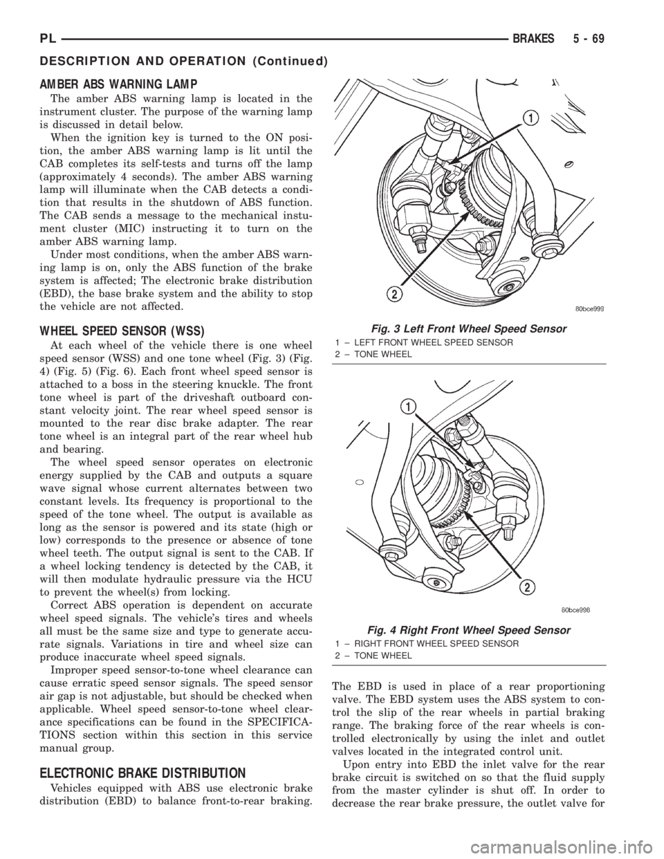
speed sensor (WSS) and one tone wheel (Fig. 3) (Fig.
4) (Fig. 5) (Fig. 6). Each front wheel speed sensor is
attached to a boss in the steering knuckle. The front
tone wheel is part of the driveshaft outboard con-
stant velocity joint. The rear wheel speed sensor is
mounted to the rear disc brake adapter. The rear
tone wheel is an integral part of the rear wheel hub
and bearing.
The wheel speed sensor operates on electronic
energy supplied by the CAB and outputs a square
wave signal whose current alternates between two
constant levels. Its frequency is proportional to the
speed of the tone wheel. The output is available as
long as the sensor is powered and its state (high or
low) corresponds to the presence or absence of tone
wheel teeth. The output signal is sent to the CAB. If
a wheel locking tendency is detected by the CAB, it
will then modulate hydraulic pressure via the HCU
to prevent the wheel(s) from locking.
Correct ABS operation is dependent on accurate
wheel speed signals. The vehicle's tires and wheels
all must be the same size and type to generate accu-
rate signals. Variations in tire and wheel size can
produce inaccurate wheel speed signals.
Improper speed sensor-to-tone wheel clearance can
cause erratic speed sensor signals. The speed sensor
air gap is not adjustable, but should be checked when
applicable. Wheel speed sensor-to-tone wheel clear-
ance specifications can be found in the SPECIFICA-
TIONS section within this section in this service
manual group.
ELECTRONIC BRAKE DISTRIBUTION
Vehicles equipped with ABS use electronic brake
distribution (EBD) to balance front-to-rear braking.The EBD is used in place of a rear proportioning
valve. The EBD system uses the ABS system to con-
trol the slip of the rear wheels in partial braking
range. The braking force of the rear wheels is con-
trolled electronically by using the inlet and outlet
valves located in the integrated control unit.
Upon entry into EBD the inlet valve for the rear
brake circuit is switched on so that the fluid supply
from the master cylinder is shut off. In order to
decrease the rear brake pressure, the outlet valve for
Fig. 3 Left Front Wheel Speed Sensor
1 ± LEFT FRONT WHEEL SPEED SENSOR
2 ± TONE WHEEL
Fig. 4 Right Front Wheel Speed Sensor
1 ± RIGHT FRONT WHEEL SPEED SENSOR
2 ± TONE WHEEL
PLBRAKES 5 - 69
DESCRIPTION AND OPERATION (Continued)
Page 155 of 1285
junction block. A label on the underside of the PDC
cover identifies the locations of the ABS fuses.
(2) Inspect the 25-way electrical connector at the
CAB for damaged, spread, or backed-out wiring ter-
minals. Verify that the 25-way connector is fully
inserted in the socket of the CAB. Be sure that wires
are not stretched tight or pulled out of the connector.
(3) Verify that all the wheel speed sensor connec-
tions are secure.
(4) Look for poor mating of connector halves or ter-
minals not fully seated in the connector body.
(5)
Check for improperly formed or damaged termi-
nals. All connector terminals in a suspect circuit should
be carefully reformed to increase contact tension.
(6) Look for poor terminal-to-wire connections.
This requires removing the terminal from the connec-
tor body to inspect it.
(7) Verify pin presence in the connector assembly
(8) Check for proper ground connections. Check all
ground connections for signs of corrosion, loose fas-
teners, or other potential defects. Refer to the wiring
diagrams for ground locations.
(9) Look for problems with the main power sources
of the vehicle. Inspect the battery, generator, ignition
circuits and other related relays and fuses.
If a visual check does not find the cause of the
problem, operate the car in an attempt to duplicate
the condition and record any trouble codes.
Most failures of the ABS disable the ABS function
for the entire ignition cycle even if the fault clears
before key-off. There are some failure conditions,
however, that allow ABS operation to resume during
the ignition cycle in which the trouble occurred even
if the trouble conditions are no longer present.
The following trouble conditions may result in
intermittent illumination of the amber ABS warning
lamp.
²Low system voltage. If Low System Voltage is
detected by the CAB, the CAB will turn on the ABS
Warning Lamp until normal system voltage is
achieved. Once normal voltage is seen at the CAB,
normal operation resumes.
²High system voltage. If high system voltage is
detected by the CAB, the CAB will turn on the
Amber ABS Warning Lamp until normal system volt-
age is achieved. Once normal voltage is again
detected by the CAB, normal ABS operation resumes.
Additional possible causes that may result in the
illumination of the amber ABS warning lamp are as
follows:
²Any condition that interrupts electrical current
to the CAB may cause the amber ABS warning lamp
to turn on intermittently.
²If PCI communication between the body control-
ler and the CAB is interrupted, the body controller
can turn on the amber ABS warning lamp.
TONE WHEEL
Tone wheels can cause erratic wheel speed sensor
signals. Inspect tone wheels for the following possible
causes:
²missing, chipped, or broken teeth
²contact with the wheel speed sensor
²wheel speed sensor to tone wheel alignment
²wheel speed sensor to tone wheel clearance
²excessive tone wheel runout
²tone wheel loose on its mounting surface
If a front tone wheel is found to need replacement,
the drive shaft must be replaced. No attempt should
be made to replace just the tone wheel. Refer to the
DIFFERENTIAL AND DRIVELINE group in this
service manual for removal and installation.
If a rear tone wheel is found to need replacement,
the rear hub and bearing must be replaced. No
attempt should be made to replace just the tone
wheel. Refer to the SUSPENSION group in this ser-
vice manual for removal and installation.
If wheel speed sensor to tone wheel contact is evi-
dent, determine the cause and correct it before
replacing the wheel speed sensor or tone wheel.
Check the gap between the speed sensor head and
the tone wheel to ensure it is within specifications.
Refer to SPECIFICATIONS in this section of the ser-
vice manual for the minimum and maximum wheel
speed sensor to tone wheel clearance.
Excessive wheel speed sensor runout can cause
erratic wheel speed sensor signals. Refer to SPECI-
FICATIONS in this section of the service manual for
the maximum allowed tone wheel runout. If tone
wheel runout is excessive, determine if it is caused
by a defect in the driveshaft assembly or hub and
bearing. Replace as necessary.
Tone wheels are pressed onto their mounting sur-
faces and should not rotate independently from the
mounting surface. Replacement of the front drive-
shaft or rear hub and bearing is necessary.
BRAKE FLUID CONTAMINATION
Indications of fluid contamination are swollen or
deteriorated rubber parts. Swelling indicates the
presence of petroleum in the brake fluid.
To test for contamination, put a small amount of
drained brake fluid in clear glass jar. If the fluid sep-
arates into layers, there is mineral oil or other fluid
contamination of the brake fluid.
If the brake fluid is contaminated, drain and thor-
oughly flush the brake system. Replace all the rubber
parts or components containing rubber coming into
contact with the brake fluid including: the master
cylinder; proportioning valves; caliper seals; wheel
cylinder seals; ABS hydraulic control unit; and all
hydraulic fluid hoses.
5 - 76 BRAKESPL
DIAGNOSIS AND TESTING (Continued)
Page 238 of 1285
OPERATION
The Automatic Shutdown (ASD) relay supplies bat-
tery voltage to the fuel injectors, electronic ignition
coil and the heating elements in the oxygen sensors.
A buss bar in the Power Distribution Center (PDC)
supplies voltage to the solenoid side and contact side
of the relay. The fuse also protects the power circuit
for the fuel pump relay and pump. The fuse is
located in the PDC. Refer to the Wiring Diagrams for
circuit information.
The PCM controls the ASD relay by switching the
ground path for the solenoid side of the relay on and
off. The PCM turns the ground path off when the
ignition switch is in the Off position. When the igni-
tion switch is in On or Start, the PCM monitors the
crankshaft and camshaft position sensor signals to
determine engine speed and ignition timing (coil
dwell). If the PCM does not receive crankshaft and
camshaft position sensor signals when the ignition
switch is in the Run position, it will de-energize the
ASD relay.
CRANKSHAFT POSITION SENSORÐPCM
INPUT
DESCRIPTION
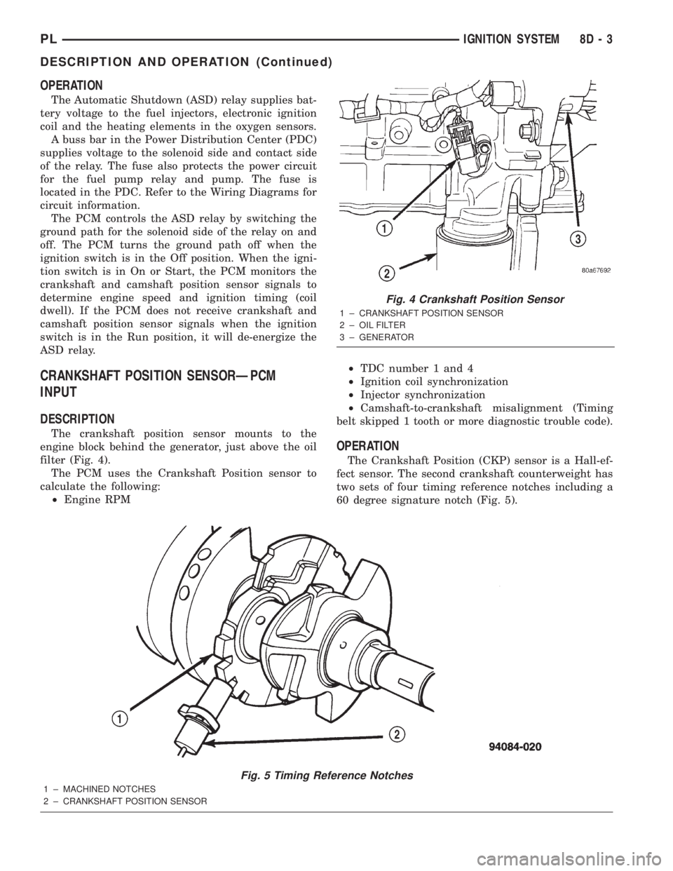
The crankshaft position sensor mounts to the
engine block behind the generator, just above the oil
filter (Fig. 4).
The PCM uses the Crankshaft Position sensor to
calculate the following:
²Engine RPM²TDC number 1 and 4
²Ignition coil synchronization
²Injector synchronization
²Camshaft-to-crankshaft misalignment (Timing
belt skipped 1 tooth or more diagnostic trouble code).
OPERATION
The Crankshaft Position (CKP) sensor is a Hall-ef-
fect sensor. The second crankshaft counterweight has
two sets of four timing reference notches including a
60 degree signature notch (Fig. 5).
Fig. 5 Timing Reference Notches
1 ± MACHINED NOTCHES
2 ± CRANKSHAFT POSITION SENSOR
Fig. 4 Crankshaft Position Sensor
1 ± CRANKSHAFT POSITION SENSOR
2 ± OIL FILTER
3 ± GENERATOR
PLIGNITION SYSTEM 8D - 3
DESCRIPTION AND OPERATION (Continued)
Page 249 of 1285
DESCRIPTION AND OPERATION
HEADLAMP SWITCH
The headlamp switch is part of the Multi-Function
Switch. Refer to Group 8J, Turn Signal and Flasher
for the Multi-Function Switch Test, Removal and
Installation procedures.
INSTRUMENT CLUSTER
There are two conventional instrument cluster
assemblies available. The clusters electronically drive
the speedometer, odometer, gauges, and tachometer
(if equipped). Refer to (Fig. 2) and (Fig. 3).
The instrument cluster controls the courtesy
lamps, it receives and sends messages to other mod-
ules via the PCI bus circuit, it controls all the instru-
ment illumination and the chime is also an integral
part of the cluster. The front turn signals are wired
through the cluster and then go to the front lamps.
The reason being that the DRL module is built into
the cluster (if equipped).
All gauges in the electronic clusters are the analog
type gauges. When the ignition switch is moved to
the OFF position, the cluster drives each gauge to its
lowest position. The individual gauges are not servi-
cable and require complete replacement of the cluster
if one or more gauges are inoperable.
One button is used to switch the display from trip
to total mileage. Holding the button when the display
is in the trip mode will reset the trip mileage. This
button is also used to put the cluster in self-diagnos-
tic mode. Refer to Service Procedures, Cluster Self-
Diagnostics in this section. Most of the indicators will
come on briefly for a bulb heck when the ignition is
turned from OFF to ON. All of the LED's are replace-
able.
In the event that the instrument cluster looses
communication with all other modules on the PCI
bus, the cluster will display ªnobusº in the VF dis-
play. The VF display also displays ªDoorº, ªCruiseº,
ªTracº, and odometer trip or total.
If the cluster does not detect voltage on the cour-
tesy lamp circuit, the message ªFUSEº will alternate
with the odometer/trip odometer for 30 seconds after
the ignition is turned on and for 15 seconds after the
vehicle is first moved. The lack of voltage can be due
to the M1 Fused B(+) (IOD) fuse being open, a bad or
missing courtesy lamp bulb, or a circuit problem.
WARNING AND INDICATOR LAMPS
The instrument cluster has warning lamps and
indicators for the following systems:
²Airbag
²Anti-lock Brakes (ABS) if equipped
²Brake warning
²Charging System²Front fog lamps (if equipped)
²High beam indicator
²Low fuel (premium cluster only)
²Low oil pressure
²Malfunction indicator (service engine soon) lamp
²Right and left turn signals
²Seat belt warning
²Security system
²Trac-Off (ABS equipped vehicles only)
The instrument cluster has a Vacuum Fluorescent
(VF) display for the following systems:
²Cruise
²Door (ajar)
²Odometer
²Set (cruise)
²Trac
²Trip
DIAGNOSIS AND TESTING
AIRBAG WARNING SYSTEM
For testing of this system refer to Group 8M, Pas-
sive Restraint Systems.
BRAKE SYSTEM WARNING LAMP TEST
The brake warning lamp illuminates when the
parking brake is applied with ignition switch turned
to the ON position. The same lamp will also illumi-
nate if one of the two service brake systems fail the
when brake pedal is applied.
To test the system:
²As the ignition switch is turned to the start posi-
tion the lamp should light.
²Turn ignition switch to the ON position and
apply the parking brake. The lamp should light.
If lamp fails to light inspect for:
²A burned out lamp
²Loose, corroded or damaged socket
²A damaged circuit board
²A broken or disconnected wire at the switch
²Defective switch
To test the service brake warning system, refer to
Group 5, Brakes, Hydraulic System Control Valves.
INSTRUMENT CLUSTER LAMPS
Every time the vehicle is switched to the START/
RUN position, the cluster goes through a BULB
CHECK. This tests most of the indicator lamps and
Vacuum Fluorescent (VF) displays. If only one lamp
is out, remove the instrument cluster and replace the
defective bulb or Light Emitting Diode (LED). If
some or all of the lamps fail to light, refer to the
proper Body Diagnostics Procedures Manual.
8E - 2 INSTRUMENT PANEL SYSTEMSPL
Page 250 of 1285
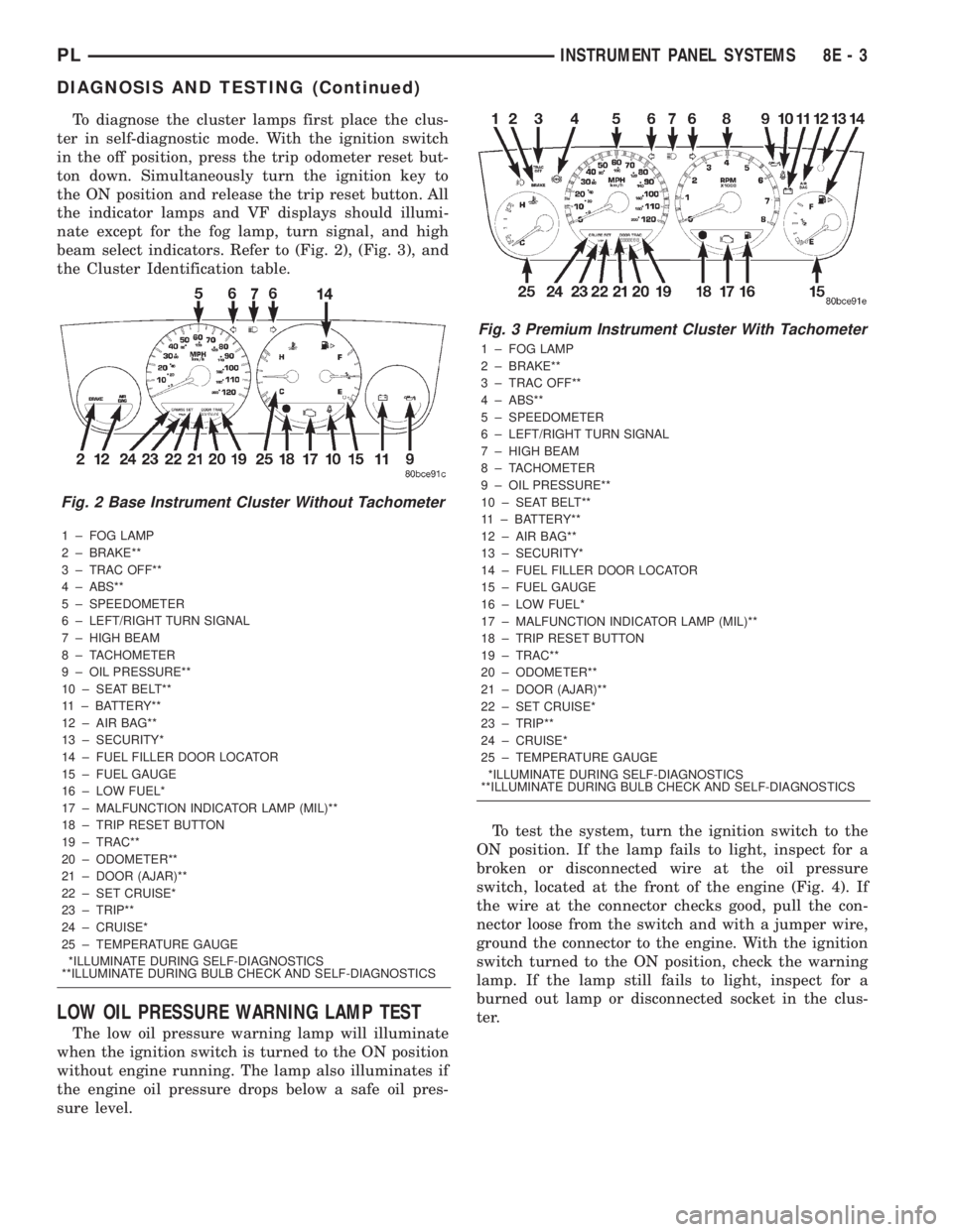
To diagnose the cluster lamps first place the clus-
ter in self-diagnostic mode. With the ignition switch
in the off position, press the trip odometer reset but-
ton down. Simultaneously turn the ignition key to
the ON position and release the trip reset button. All
the indicator lamps and VF displays should illumi-
nate except for the fog lamp, turn signal, and high
beam select indicators. Refer to (Fig. 2), (Fig. 3), and
the Cluster Identification table.
1 ± FOG LAMP
2 ± BRAKE**
3 ± TRAC OFF**
4 ± ABS**
5 ± SPEEDOMETER
6 ± LEFT/RIGHT TURN SIGNAL
7 ± HIGH BEAM
8 ± TACHOMETER
9 ± OIL PRESSURE**
10 ± SEAT BELT**
11 ± BATTERY**
12 ± AIR BAG**
13 ± SECURITY*
14 ± FUEL FILLER DOOR LOCATOR
15 ± FUEL GAUGE
16 ± LOW FUEL*
17 ± MALFUNCTION INDICATOR LAMP (MIL)**
18 ± TRIP RESET BUTTON
19 ± TRAC**
20 ± ODOMETER**
21 ± DOOR (AJAR)**
22 ± SET CRUISE*
23 ± TRIP**
24 ± CRUISE*
25 ± TEMPERATURE GAUGE
*ILLUMINATE DURING SELF-DIAGNOSTICS
**ILLUMINATE DURING BULB CHECK AND SELF-DIAGNOSTICS
LOW OIL PRESSURE WARNING LAMP TEST
The low oil pressure warning lamp will illuminate
when the ignition switch is turned to the ON position
without engine running. The lamp also illuminates if
the engine oil pressure drops below a safe oil pres-
sure level.To test the system, turn the ignition switch to the
ON position. If the lamp fails to light, inspect for a
broken or disconnected wire at the oil pressure
switch, located at the front of the engine (Fig. 4). If
the wire at the connector checks good, pull the con-
nector loose from the switch and with a jumper wire,
ground the connector to the engine. With the ignition
switch turned to the ON position, check the warning
lamp. If the lamp still fails to light, inspect for a
burned out lamp or disconnected socket in the clus-
ter.
Fig. 2 Base Instrument Cluster Without Tachometer
Fig. 3 Premium Instrument Cluster With Tachometer
1 ± FOG LAMP
2 ± BRAKE**
3 ± TRAC OFF**
4 ± ABS**
5 ± SPEEDOMETER
6 ± LEFT/RIGHT TURN SIGNAL
7 ± HIGH BEAM
8 ± TACHOMETER
9 ± OIL PRESSURE**
10 ± SEAT BELT**
11 ± BATTERY**
12 ± AIR BAG**
13 ± SECURITY*
14 ± FUEL FILLER DOOR LOCATOR
15 ± FUEL GAUGE
16 ± LOW FUEL*
17 ± MALFUNCTION INDICATOR LAMP (MIL)**
18 ± TRIP RESET BUTTON
19 ± TRAC**
20 ± ODOMETER**
21 ± DOOR (AJAR)**
22 ± SET CRUISE*
23 ± TRIP**
24 ± CRUISE*
25 ± TEMPERATURE GAUGE
*ILLUMINATE DURING SELF-DIAGNOSTICS
**ILLUMINATE DURING BULB CHECK AND SELF-DIAGNOSTICS
PLINSTRUMENT PANEL SYSTEMS 8E - 3
DIAGNOSIS AND TESTING (Continued)
Page 251 of 1285
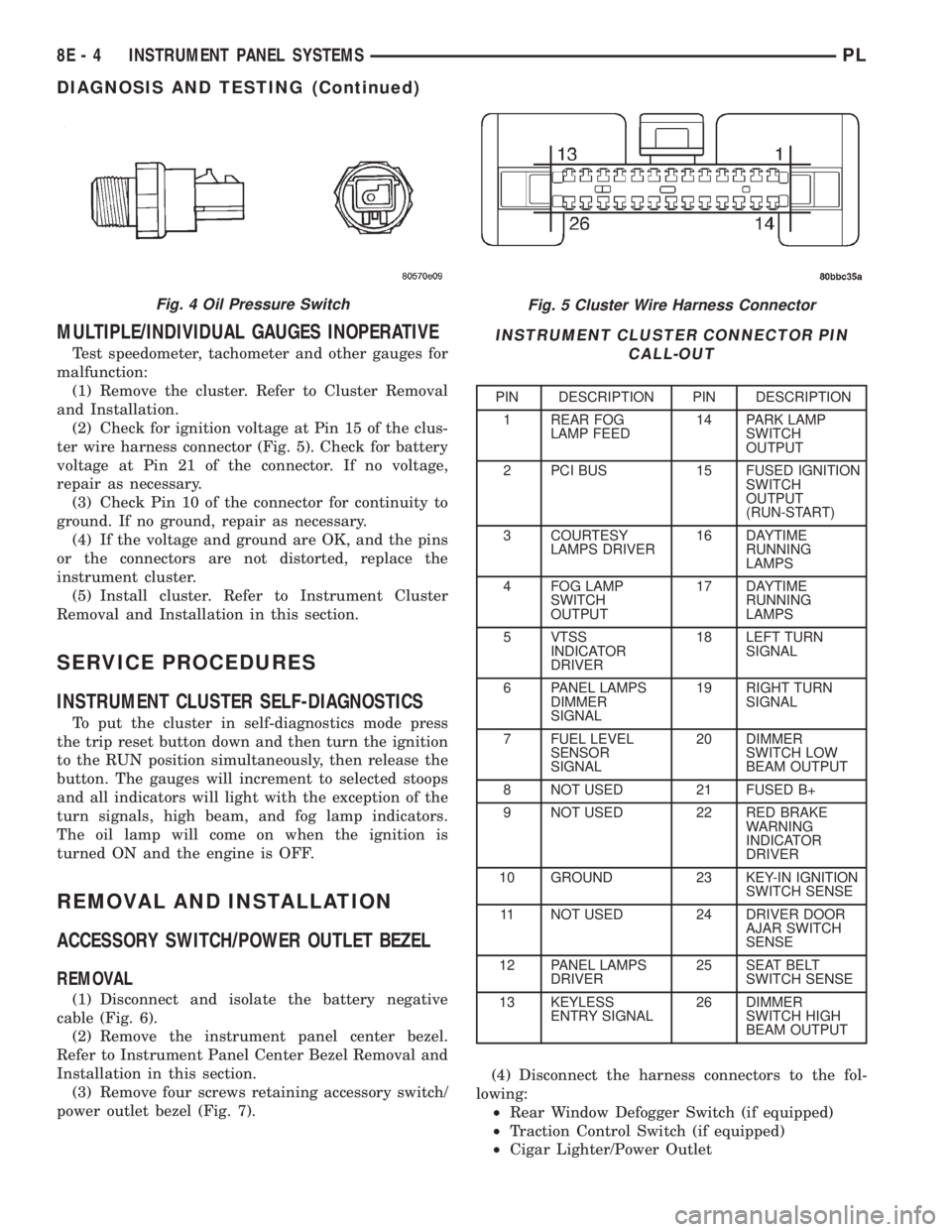
MULTIPLE/INDIVIDUAL GAUGES INOPERATIVE
Test speedometer, tachometer and other gauges for
malfunction:
(1) Remove the cluster. Refer to Cluster Removal
and Installation.
(2) Check for ignition voltage at Pin 15 of the clus-
ter wire harness connector (Fig. 5). Check for battery
voltage at Pin 21 of the connector. If no voltage,
repair as necessary.
(3) Check Pin 10 of the connector for continuity to
ground. If no ground, repair as necessary.
(4) If the voltage and ground are OK, and the pins
or the connectors are not distorted, replace the
instrument cluster.
(5) Install cluster. Refer to Instrument Cluster
Removal and Installation in this section.
SERVICE PROCEDURES
INSTRUMENT CLUSTER SELF-DIAGNOSTICS
To put the cluster in self-diagnostics mode press
the trip reset button down and then turn the ignition
to the RUN position simultaneously, then release the
button. The gauges will increment to selected stoops
and all indicators will light with the exception of the
turn signals, high beam, and fog lamp indicators.
The oil lamp will come on when the ignition is
turned ON and the engine is OFF.
REMOVAL AND INSTALLATION
ACCESSORY SWITCH/POWER OUTLET BEZEL
REMOVAL
(1) Disconnect and isolate the battery negative
cable (Fig. 6).
(2) Remove the instrument panel center bezel.
Refer to Instrument Panel Center Bezel Removal and
Installation in this section.
(3) Remove four screws retaining accessory switch/
power outlet bezel (Fig. 7).(4) Disconnect the harness connectors to the fol-
lowing:
²Rear Window Defogger Switch (if equipped)
²Traction Control Switch (if equipped)
²Cigar Lighter/Power Outlet
Fig. 5 Cluster Wire Harness Connector
INSTRUMENT CLUSTER CONNECTOR PIN
CALL-OUT
PIN DESCRIPTION PIN DESCRIPTION
1 REAR FOG
LAMP FEED14 PARK LAMP
SWITCH
OUTPUT
2 PCI BUS 15 FUSED IGNITION
SWITCH
OUTPUT
(RUN-START)
3 COURTESY
LAMPS DRIVER16 DAYTIME
RUNNING
LAMPS
4 FOG LAMP
SWITCH
OUTPUT17 DAYTIME
RUNNING
LAMPS
5 VTSS
INDICATOR
DRIVER18 LEFT TURN
SIGNAL
6 PANEL LAMPS
DIMMER
SIGNAL19 RIGHT TURN
SIGNAL
7 FUEL LEVEL
SENSOR
SIGNAL20 DIMMER
SWITCH LOW
BEAM OUTPUT
8 NOT USED 21 FUSED B+
9 NOT USED 22 RED BRAKE
WARNING
INDICATOR
DRIVER
10 GROUND 23 KEY-IN IGNITION
SWITCH SENSE
11 NOT USED 24 DRIVER DOOR
AJAR SWITCH
SENSE
12 PANEL LAMPS
DRIVER25 SEAT BELT
SWITCH SENSE
13 KEYLESS
ENTRY SIGNAL26 DIMMER
SWITCH HIGH
BEAM OUTPUT
Fig. 4 Oil Pressure Switch
8E - 4 INSTRUMENT PANEL SYSTEMSPL
DIAGNOSIS AND TESTING (Continued)