2000 DODGE NEON child lock
[x] Cancel search: child lockPage 364 of 1285

POWER LOCK SYSTEMS
TABLE OF CONTENTS
page page
POWER DOOR LOCKS...................... 1REMOTE KEYLESS ENTRY (RKE).............. 4
POWER DOOR LOCKS
TABLE OF CONTENTS
page page
DESCRIPTION AND OPERATION
INTRODUCTION..........................1
POWER DOOR LOCKS.....................2
CHILD PROTECTION LOCKS................2
DOOR LOCK INHIBIT.......................2
DIAGNOSIS AND TESTING
DOOR LOCK MOTOR......................2
DOOR LOCK SWITCH......................2SERVICE PROCEDURES
DOUBLE ACTIVATION UNLOCK...............3
ROLLING DOOR LOCKS....................3
REMOVAL AND INSTALLATION
DOOR LOCK MOTOR/LATCH.................3
DOOR LOCK SWITCH......................3
REMOTE KEYLESS ENTRY (RKE) MODULE.....3
DESCRIPTION AND OPERATION
INTRODUCTION
All doors can be locked or unlocked electrically by
operating the switch on either front door panel.
When the door lock switch is activated the Remote
Keyless Entry Module provides power to the door
lock motors through relays internal to the module.
The Remote Keyless Entry (RKE) Module also con-
trols the Vehicle Theft Security System (VTSS).
All doors can be locked or unlocked mechanically
and independently with their respective locking
knobs. The front doors can also be unlocked by actu-
ation of the inside remote door handle.
The RKE Module has three modes of operation
including customer usage mode, dealer lot storage
mode, and shipping mode. The customer usage mode
provides full functionality of the module and is the
mode in which the RKE module should be operating
when used by the customer. Dealer lot storage mode
and shipping modes are reduced power modes meant
to extend vehicle battery life during shipping and
storage in the dealer lot. Dealer lot storage mode pro-
vides limited VTSS and power door lock functions,
but disables the Remote Keyless Entry (RKE) func-
tions. This mode is intended to be used when the
vehicle is on the dealer lot to provide VTSS coverageof the vehicle while minimizing battery drain. Ship-
ping mode disables all normal functions (i.e. power
door locks, RKE, and VTSS) of the module, and is
intended to be used when the vehicle is shipped from
the assembly plant.
NOTE: The dealer must remove the module from
ªShip Modeº and place the RKE Module into either
the ªDealer Lotº storage or ªCustomer Usageº
modes of operation after receiving the vehicle from
the assembly plant. Refer to Group 8Q-Vehicle
Theft/Security Systems, Switching Operating
Modes/Configuring a New Module under Service
Procedures.
CENTRAL LOCKING/UNLOCKING
The door locks can be locked or unlocked electri-
cally via the exterior door key cylinders to provide
the central locking/unlocking feature. The central
locking/unlocking feature incorporates a customer
programmable ``Double activation unlockº feature
which operates in the following manner: When
enabled, the first turn of the key cylinder to the
UNLOCK position (toward the front of the vehicle)
will mechanically unlock the door whose key cylinder
is being turned. A second turn of the key cylinder to
the UNLOCK position (within five seconds of the
PLPOWER LOCK SYSTEMS 8P - 1
Page 365 of 1285

first turn) will cause all vehicle doors to unlock elec-
trically. When this feature is disabled, all vehicle
doors will be unlocked electrically upon the first turn
of a key cylinder to the UNLOCK position. The vehi-
cle is locked electrically by turning the key cylinder
to the LOCK position once, regardless of the state of
the double activation unlock feature.
POWER DOOR LOCKS
The Remote Keyless Entry (RKE) Module actuates
the power door lock relays when a door lock switch is
activated. If the door lock switch is pressed for longer
than eight consecutive seconds, the RKE module will
de-energize the door lock motors.
The system includes the rolling door locking fea-
ture. The vehicle is shipped with the system enabled.
When the system is disabled the door locks will work
by use of the door lock switches and the Remote Key-
less Entry system only. When the rolling door lock
system is enabled, the RKE module will automati-
cally lock all the vehicle doors when all of the follow-
ing conditions are met:
²All doors are closed
²The vehicle speed exceeds 15 +/- 1 mph.
²The throttle position sensor tip-in is greater
than 10 +/- 2 degrees.
The RKE module will automatically re-lock all
doors if the above conditions are met and if any of
the doors become ajar and then closed again.
The enabling/disabling of the rolling door lock fea-
ture is customer programmable, as well as program-
mable with the DRB IIItscan tool.
The power lock motors are also equipped with a
thermal protection system which prevents the motors
from burning out. The motors may chatter if they are
continuously activated.
CHILD PROTECTION LOCKS
The child protection locks are on the rear doors
only. The lock, when engaged, will disable the inside
door handle from opening the door. The lock is part
of the latch/lock assembly. The lock is engaged by
moving a lever that is located on the rearward inside
edge of the door.
DOOR LOCK INHIBIT
With the key in the ignition switch and the driver
door open, the Remote Keyless Entry (RKE) Modulewill ignore the command to lock the power door locks
via the interior driver door lock switch. Once the key
is removed, or the driver door is closed, the RKE
module will allow the power door locks to lock via the
interior door lock switches.
DIAGNOSIS AND TESTING
DOOR LOCK MOTOR
(1) Make certain battery is in normal condition
and fuses powering the RKE module aren't blown
before circuits are tested.
(2) To determine which motor is faulty, check each
individual door for electrical lock and unlock or dis-
connect the motor connectors one at a time, while
operating the door lock switch.
(3) In the event that none of the motors work, the
problem maybe caused by a shorted motor, a bad
switch or a bad relay internal to the RKE module.
Disconnecting a defective motor will allow the others
to work.
(4) To test an individual door lock motor, discon-
nect the electrical connector from the motor.
(5) To lock the door, connect a 12 volt power source
to one pin of the lock motor and a ground wire to the
other pin.
(6) To unlock the door, reverse the wire connec-
tions at the motor pin terminals.
(7) If these results are NOT obtained, replace the
motor.
DOOR LOCK SWITCH
(1) Remove the switch from its mounting location,
and disconnect from vehicle wiring harness. Refer to
Door Lock Switch Removal and Installation in this
section.
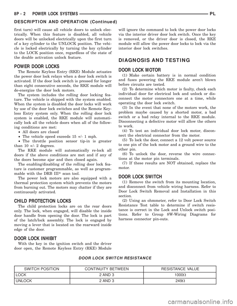
(2) Using an ohmmeter, refer to Door Lock Switch
Resistance Test table to determine if switch resis-
tance is correct in the Lock and Unlock switch posi-
tions. Refer to Group 8W-Wiring Diagrams for
harness connector pin-outs.
DOOR LOCK SWITCH RESISTANCE
SWITCH POSITION CONTINUITY BETWEEN RESISTANCE VALUE
LOCK 2 AND 3 1000V
UNLOCK 2 AND 3 249V
8P - 2 POWER LOCK SYSTEMSPL
DESCRIPTION AND OPERATION (Continued)
Page 1151 of 1285

(3) Connect latch and lock rods to door latch.
(4) Install door trim panel and water shield.
(5) Adjust door latch using procedure in this sec-
tion.
FRONT DOOR LATCH STRIKER
REMOVAL
(1) Mark outline of door latch striker on B-pillar to
aid installation.(2) Remove screws attaching door latch striker to
B-pillar (Fig. 35).
(3) Remove door latch striker from vehicle.
INSTALLATION
(1) Install door latch striker into the door.
(2) Install screws attaching door latch striker to
B-pillar loosely.
(3) Align door latch striker to outline marks on the
B-pillar
(4) Tighten screws attaching door latch striker to
B-pillar.
(5) Check door alignment and adjust as necessary.
FRONT VERTICAL GUIDE BAR
REMOVAL
(1) Remove door trim panel and water dam.
(2) Remove door speaker, if equipped.
(3) Remove front lift guide.
(4) Remove bolt attaching top of front guide bar to
inner door panel.
(5) Using a Snap-ontflare-nut socket (FRXM10)
and a hex wrench, remove nut attaching bottom of
guide bar to door panel while holding jack screws.
INSTALLATION
(1) Install nut attaching bottom of guide bar to
door panel.
(2) Install bolt attaching top of front guide bar to
inner door panel.
(3) Install front lift guide.
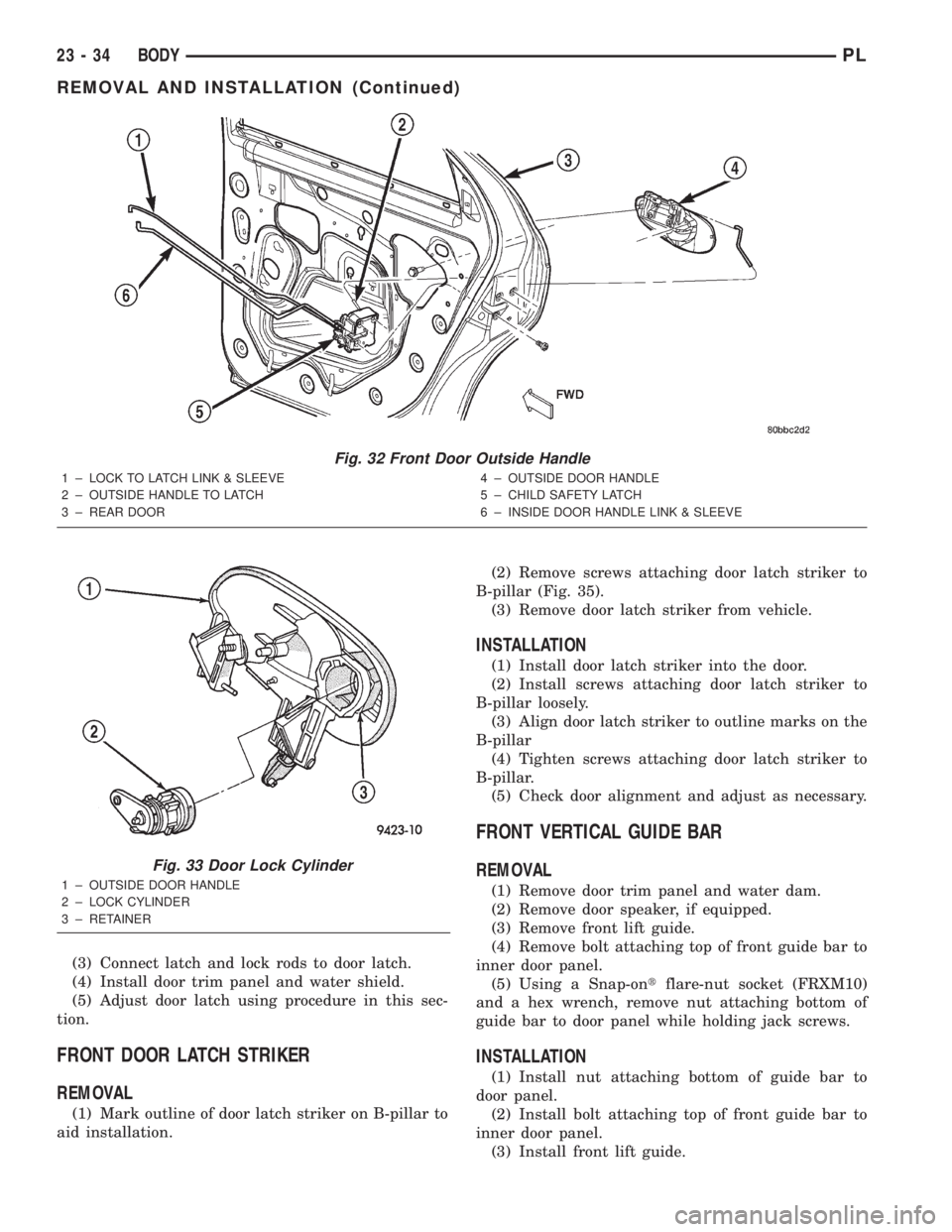
Fig. 32 Front Door Outside Handle
1 ± LOCK TO LATCH LINK & SLEEVE
2 ± OUTSIDE HANDLE TO LATCH
3 ± REAR DOOR4 ± OUTSIDE DOOR HANDLE
5 ± CHILD SAFETY LATCH
6 ± INSIDE DOOR HANDLE LINK & SLEEVE
Fig. 33 Door Lock Cylinder
1 ± OUTSIDE DOOR HANDLE
2 ± LOCK CYLINDER
3 ± RETAINER
23 - 34 BODYPL
REMOVAL AND INSTALLATION (Continued)
Page 1159 of 1285

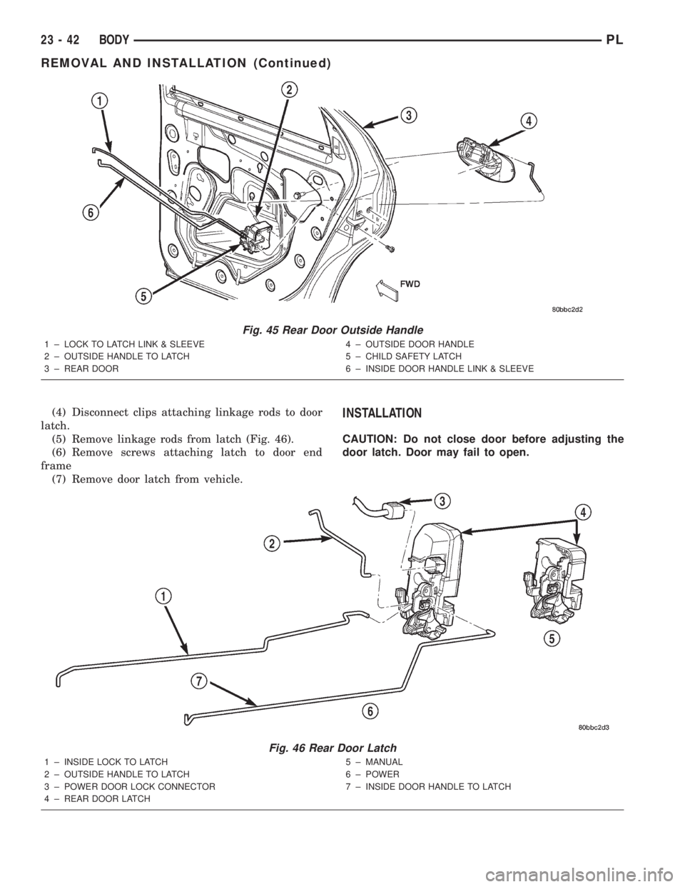
(4) Disconnect clips attaching linkage rods to door
latch.
(5) Remove linkage rods from latch (Fig. 46).
(6) Remove screws attaching latch to door end
frame
(7) Remove door latch from vehicle.INSTALLATION
CAUTION: Do not close door before adjusting the
door latch. Door may fail to open.
Fig. 45 Rear Door Outside Handle
1 ± LOCK TO LATCH LINK & SLEEVE
2 ± OUTSIDE HANDLE TO LATCH
3 ± REAR DOOR4 ± OUTSIDE DOOR HANDLE
5 ± CHILD SAFETY LATCH
6 ± INSIDE DOOR HANDLE LINK & SLEEVE
Fig. 46 Rear Door Latch
1 ± INSIDE LOCK TO LATCH
2 ± OUTSIDE HANDLE TO LATCH
3 ± POWER DOOR LOCK CONNECTOR
4 ± REAR DOOR LATCH5 ± MANUAL
6 ± POWER
7 ± INSIDE DOOR HANDLE TO LATCH
23 - 42 BODYPL
REMOVAL AND INSTALLATION (Continued)