2000 DODGE NEON alarm
[x] Cancel search: alarmPage 324 of 1285
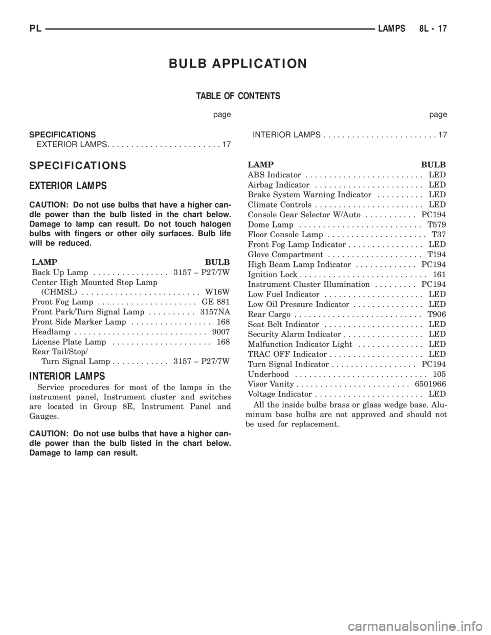
BULB APPLICATION
TABLE OF CONTENTS
page page
SPECIFICATIONS
EXTERIOR LAMPS........................17INTERIOR LAMPS........................17
SPECIFICATIONS
EXTERIOR LAMPS
CAUTION: Do not use bulbs that have a higher can-
dle power than the bulb listed in the chart below.
Damage to lamp can result. Do not touch halogen
bulbs with fingers or other oily surfaces. Bulb life
will be reduced.
LAMP BULB
Back Up Lamp................3157 ± P27/7W
Center High Mounted Stop Lamp
(CHMSL).........................W16W
Front Fog Lamp..................... GE881
Front Park/Turn Signal Lamp..........3157NA
Front Side Marker Lamp................. 168
Headlamp............................9007
License Plate Lamp..................... 168
Rear Tail/Stop/
Turn Signal Lamp............3157 ± P27/7W
INTERIOR LAMPS
Service procedures for most of the lamps in the
instrument panel, Instrument cluster and switches
are located in Group 8E, Instrument Panel and
Gauges.
CAUTION: Do not use bulbs that have a higher can-
dle power than the bulb listed in the chart below.
Damage to lamp can result.LAMP BULB
ABS Indicator......................... LED
Airbag Indicator....................... LED
Brake System Warning Indicator.......... LED
Climate Controls....................... LED
Console Gear Selector W/Auto...........PC194
Dome Lamp..........................T579
Floor Console Lamp..................... T37
Front Fog Lamp Indicator................ LED
Glove Compartment....................T194
High Beam Lamp Indicator.............PC194
Ignition Lock........................... 161
Instrument Cluster Illumination.........PC194
Low Fuel Indicator..................... LED
Low Oil Pressure Indicator............... LED
Rear Cargo...........................T906
Seat Belt Indicator..................... LED
Security Alarm Indicator................. LED
Malfunction Indicator Light.............. LED
TRAC OFF Indicator.................... LED
Turn Signal Indicator..................PC194
Underhood............................ 105
Visor Vanity........................6501966
Voltage Indicator....................... LED
All the inside bulbs brass or glass wedge base. Alu-
minum base bulbs are not approved and should not
be used for replacement.
PLLAMPS 8L - 17
Page 366 of 1285
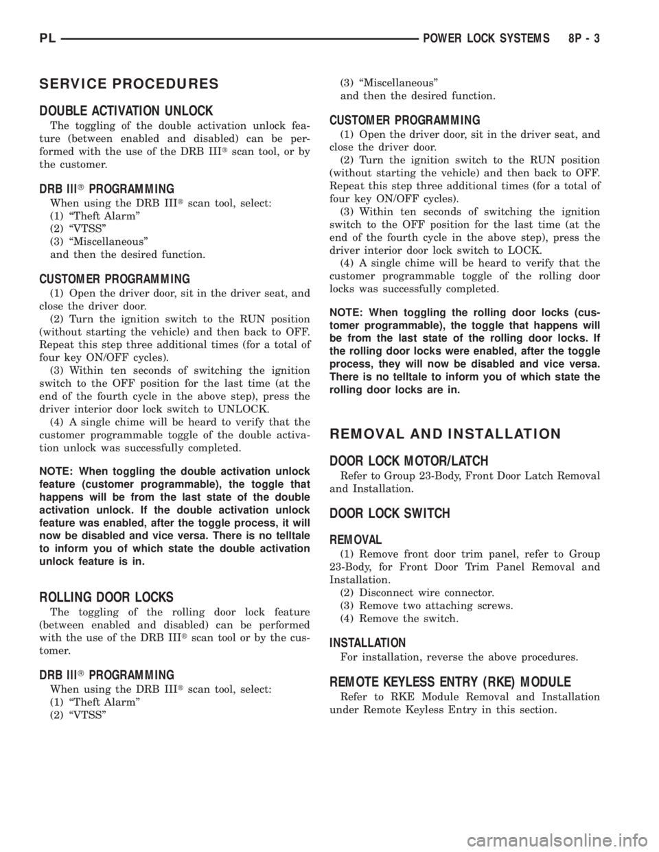
SERVICE PROCEDURES
DOUBLE ACTIVATION UNLOCK
The toggling of the double activation unlock fea-
ture (between enabled and disabled) can be per-
formed with the use of the DRB IIItscan tool, or by
the customer.
DRB lllTPROGRAMMING
When using the DRB IIItscan tool, select:
(1) ªTheft Alarmº
(2) ªVTSSº
(3) ªMiscellaneousº
and then the desired function.
CUSTOMER PROGRAMMING
(1) Open the driver door, sit in the driver seat, and
close the driver door.
(2) Turn the ignition switch to the RUN position
(without starting the vehicle) and then back to OFF.
Repeat this step three additional times (for a total of
four key ON/OFF cycles).
(3) Within ten seconds of switching the ignition
switch to the OFF position for the last time (at the
end of the fourth cycle in the above step), press the
driver interior door lock switch to UNLOCK.
(4) A single chime will be heard to verify that the
customer programmable toggle of the double activa-
tion unlock was successfully completed.
NOTE: When toggling the double activation unlock
feature (customer programmable), the toggle that
happens will be from the last state of the double
activation unlock. If the double activation unlock
feature was enabled, after the toggle process, it will
now be disabled and vice versa. There is no telltale
to inform you of which state the double activation
unlock feature is in.
ROLLING DOOR LOCKS
The toggling of the rolling door lock feature
(between enabled and disabled) can be performed
with the use of the DRB IIItscan tool or by the cus-
tomer.
DRB lllTPROGRAMMING
When using the DRB IIItscan tool, select:
(1) ªTheft Alarmº
(2) ªVTSSº(3) ªMiscellaneousº
and then the desired function.
CUSTOMER PROGRAMMING
(1) Open the driver door, sit in the driver seat, and
close the driver door.
(2) Turn the ignition switch to the RUN position
(without starting the vehicle) and then back to OFF.
Repeat this step three additional times (for a total of
four key ON/OFF cycles).
(3) Within ten seconds of switching the ignition
switch to the OFF position for the last time (at the
end of the fourth cycle in the above step), press the
driver interior door lock switch to LOCK.
(4) A single chime will be heard to verify that the
customer programmable toggle of the rolling door
locks was successfully completed.
NOTE: When toggling the rolling door locks (cus-
tomer programmable), the toggle that happens will
be from the last state of the rolling door locks. If
the rolling door locks were enabled, after the toggle
process, they will now be disabled and vice versa.
There is no telltale to inform you of which state the
rolling door locks are in.
REMOVAL AND INSTALLATION
DOOR LOCK MOTOR/LATCH
Refer to Group 23-Body, Front Door Latch Removal
and Installation.
DOOR LOCK SWITCH
REMOVAL
(1) Remove front door trim panel, refer to Group
23-Body, for Front Door Trim Panel Removal and
Installation.
(2) Disconnect wire connector.
(3) Remove two attaching screws.
(4) Remove the switch.
INSTALLATION
For installation, reverse the above procedures.
REMOTE KEYLESS ENTRY (RKE) MODULE
Refer to RKE Module Removal and Installation
under Remote Keyless Entry in this section.
PLPOWER LOCK SYSTEMS 8P - 3
Page 368 of 1285
NOTE: The dealer must remove the module from
ªShip Modeº and place the RKE Module into either
the ªDealer Lotº storage or ªCustomer Usageº
modes of operation after receiving the vehicle from
the assembly plant. Refer to Group 8Q-Vehicle
Theft/Security Systems, Switching Operating
Modes/Configuring a New Module under Service
Procedures.
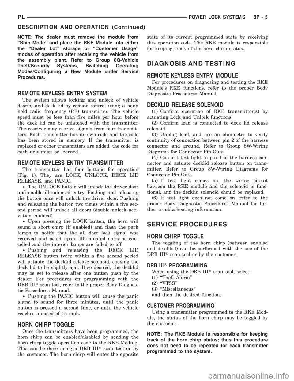
REMOTE KEYLESS ENTRY SYSTEM
The system allows locking and unlock of vehicle
door(s) and deck lid by remote control using a hand
held radio frequency (RF) transmitter. The vehicle
speed must be less than five miles per hour before
the deck lid can be unlatched with the transmitter.
The receiver may receive signals from four transmit-
ters. Each transmitter has its own code and the code
has been stored in memory. If the transmitter is
replaced or other transmitters are added, the code for
each unit must be learned.
REMOTE KEYLESS ENTRY TRANSMITTER
The transmitter has four buttons for operation
(Fig. 1). They are LOCK, UNLOCK, DECK LID
RELEASE, and PANIC.
²The UNLOCK button will unlock the driver door
and enable illuminated entry. Pushing and releasing
the button once will unlock the driver door. Pushing
and releasing the button two times within a five sec-
ond period will unlock all doors (double unlock acti-
vation enabled).
²Upon pressing the LOCK button, the horn will
sound a short chirp (if enabled) and flash the park
lamps to notify that the all door lock signal was
received and acted upon. Illuminated entry is can-
celled and the interior lamps are faded to off.
²Pushing and releasing the DECK LID
RELEASE button twice within a five second period
will actuate the decklid release solenoid, causing the
deck lid to be slightly ajar. If so desired, the decklid
may be set to release after one button push by the
dealer. For procedures on programming with the
DRB IIItscan tool, refer to the proper Body Diagnos-
tic Procedures Manual.
²Pushing the PANIC button will cause the panic
alarm to sound for three minutes, until the panic
button is pressed a second time, or until the vehicle
reaches a speed of 15 mph.
HORN CHIRP TOGGLE
Once the transmitters have been programmed, the
horn chirp can be enabled/disabled by sending the
horn chirp toggle operation code to the RKE Module.
This can be done using a DRB IIItscan tool or by
the customer. The horn chirp will enter the oppositestate of its current programmed state by receiving
this operation code. The RKE module is responsible
for keeping track of the horn chirp status.
DIAGNOSIS AND TESTING
REMOTE KEYLESS ENTRY MODULE
For procedures on diagnosing and testing the RKE
Module's RKE functions, refer to the proper Body
Diagnostic Procedures Manual.
DECKLID RELEASE SOLENOID
(1) Confirm operation of RKE transmitter(s) by
actuating Lock and Unlock functions.
(2) Confirm lead is connected to deck lid release
solenoid.
(3) Unplug lead, and use an ohmmeter to verify
continuity of connection between pin 2 of the harness
connector and ground. Refer to Group 8W-Wiring
Diagrams for Connector Pin-Outs.
(4) Connect test light to pin 1 of the harness con-
nector and actuate decklid release button on trans-
mitter. Refer to Group 8W-Wiring Diagrams for
Connector Pin-Outs.
(5) If test light comes on, the wiring circuit
between the RKE module and the solenoid is func-
tional, and the decklid solenoid should be replaced.
(6) If test light does not come on, refer to the
proper Body Diagnostic Procedures Manual for fur-
ther troubleshooting information.
SERVICE PROCEDURES
HORN CHIRP TOGGLE
The toggling of the horn chirp (between enabled
and disabled) can be performed with the use of the
DRB IIItscan tool or by the customer.
DRB lllTPROGRAMMING
When using the DRB IIItscan tool, select:
(1) ªTheft Alarmº
(2) ªVTSSº
(3) ªMiscellaneousº
and then the desired function.
CUSTOMER PROGRAMMING
Using a transmitter programmed to the RKE Mod-
ule, the status of the horn chirp may be toggled by
the customer.
NOTE: The RKE Module is responsible for keeping
track of the horn chirp status; thus this procedure
does not need to be repeated for each transmitter
programmed to the system.
PLPOWER LOCK SYSTEMS 8P - 5
DESCRIPTION AND OPERATION (Continued)
Page 369 of 1285
(1) With the ignition switch in RUN position, press
and hold the transmitter Unlock button (Fig. 1) for a
minimum of 4 seconds to a maximum of 10 seconds.
(2) Within the 4-10 second range, depress the
transmitter Lock button (Fig. 1). A chime will be
heard to indicate a successful toggle, at which time
the buttons may be released.
SWITCHING OPERATING MODES/
CONFIGURING A NEW MODULE
Refer to Group 8Q-Vehicle Theft/Security Systems,
Switching Operating Modes/Configuring A New Mod-
ule under Service Procedures.
TRANSMITTER PROGRAMMING
The Remote Keyless Entry transmitters can be
programmed with the use of the DRB IIItscan tool
or by the customer.
DRB lllTPROGRAMMING
When using the DRB IIItscan tool, select:
(1) ªTheft Alarmº
(2) ªVTSSº
(3) ªMiscellaneousº
and then the desired function.
CUSTOMER PROGRAMMING
For a customer to be able to program RKE trans-
mitters themselves, at least one RKE transmitter
must be programmed already. This procedure is to
add additional transmitters. If all transmitters are
lost, the DRB IIItscan tool must be used to program
the new transmitters.
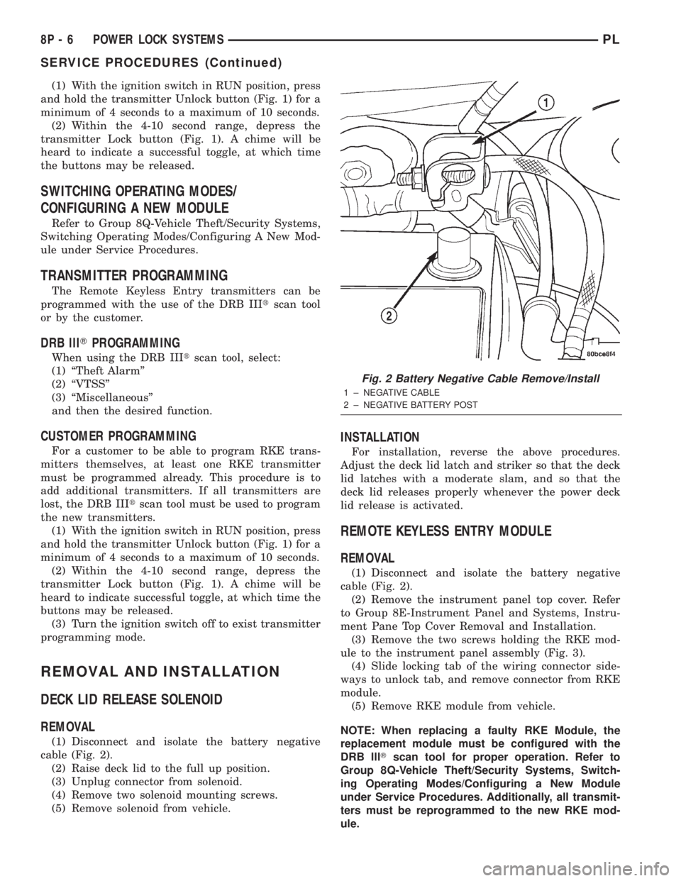
(1) With the ignition switch in RUN position, press
and hold the transmitter Unlock button (Fig. 1) for a
minimum of 4 seconds to a maximum of 10 seconds.
(2) Within the 4-10 second range, depress the
transmitter Lock button (Fig. 1). A chime will be
heard to indicate successful toggle, at which time the
buttons may be released.
(3) Turn the ignition switch off to exist transmitter
programming mode.
REMOVAL AND INSTALLATION
DECK LID RELEASE SOLENOID
REMOVAL
(1) Disconnect and isolate the battery negative
cable (Fig. 2).
(2) Raise deck lid to the full up position.
(3) Unplug connector from solenoid.
(4) Remove two solenoid mounting screws.
(5) Remove solenoid from vehicle.
INSTALLATION
For installation, reverse the above procedures.
Adjust the deck lid latch and striker so that the deck
lid latches with a moderate slam, and so that the
deck lid releases properly whenever the power deck
lid release is activated.
REMOTE KEYLESS ENTRY MODULE
REMOVAL
(1) Disconnect and isolate the battery negative
cable (Fig. 2).
(2) Remove the instrument panel top cover. Refer
to Group 8E-Instrument Panel and Systems, Instru-
ment Pane Top Cover Removal and Installation.
(3) Remove the two screws holding the RKE mod-
ule to the instrument panel assembly (Fig. 3).
(4) Slide locking tab of the wiring connector side-
ways to unlock tab, and remove connector from RKE
module.
(5) Remove RKE module from vehicle.
NOTE: When replacing a faulty RKE Module, the
replacement module must be configured with the
DRB lllTscan tool for proper operation. Refer to
Group 8Q-Vehicle Theft/Security Systems, Switch-
ing Operating Modes/Configuring a New Module
under Service Procedures. Additionally, all transmit-
ters must be reprogrammed to the new RKE mod-
ule.
Fig. 2 Battery Negative Cable Remove/Install
1 ± NEGATIVE CABLE
2 ± NEGATIVE BATTERY POST
8P - 6 POWER LOCK SYSTEMSPL
SERVICE PROCEDURES (Continued)
Page 373 of 1285
VTSS disarming occurs upon normal vehicle entry
by unlocking either door via the key cylinders or
RKE transmitter, or by starting the vehicle with a
valid Sentry Key. This disarming will also halt the
alarm once it has been activated.
A tamper alert exists to notify the driver that the
system had been activated. This alert consists of 3
horn pulses when the vehicle is disarmed.
The VTSS will not arm by mechanically locking the
vehicle doors. This will manually override the sys-
tem.
In the dealer lot storage mode of operation, all of
the above descriptions of the VTSS are true with the
following exceptions:
²Remote Keyless Entry functions are disabled,
and cannot be used for arming/disarming the VTSS.
²The VTSS indicator is non-operational.
SENTRY KEY IMMOBILIZER SYSTEM (SKIS)
The Sentry Key Immobilizer System (SKIS) is
designed to provide passive protection against unau-
thorized vehicle use by preventing the engine from
operating while the system is armed. The primary
components of this system are the Sentry Key Immo-
bilizer Module (SKIM), the Sentry Key transponder,
the Vehicle Theft/Security System (VTSS) indicator
LED, and the Powertrain Control Module (PCM).
The SKIM is installed on the steering column near
the ignition lock cylinder. The transponder is located
under the molded rubber cap on the head of the igni-
tion key. The VTSS indicator LED is located in the
instrument cluster.
The SKIS includes three valid Sentry Key tran-
sponders from the factory, one being a valet key. This
is so the customer can self program new keys if one
is lost. If the customer wishes, additional non-coded
blank Sentry Keys are available. These blank keys
can be cut to match a valid ignition key, but the
engine will not start unless the key transponder is
also programmed to the vehicle. The SKIS will recog-
nize no more than eight valid Sentry Key transpon-
ders at any one time.
The SKIS performs a self-test each time the igni-
tion switch is turned to the ON position, and will
store Diagnostic Trouble Codes (DTC's) if a system
malfunction is detected. The SKIS can be diagnosed,
and any stored DTC can be retrieved using a DRB
llltscan tool as described in the proper Body Diag-
nostic Procedures Manual.
SENTRY KEY IMMOBILIZER MODULE (SKIM)
The Sentry Key Immobilizer Module (SKIM) (Fig.
1) contains a Radio Frequency (RF) transceiver and a
central processing unit, which includes the Sentry
Key Immobilizer System (SKIS) program logic. The
SKIS programming enables the SKIM to programand retain in memory the codes of at least two, but
no more than eight electronically coded Sentry Key
transponders. The SKIS programming also enables
the SKIM to communicate over the Programmable
Communication Interface (PCI) bus network with the
Powertrain Control Module (PCM), the instrument
cluster and/or the DRB IIItscan tool.
The SKIM transmits and receives RF signals
through a tuned antenna enclosed within a molded
plastic ring formation that is integral to the SKIM
housing. When the SKIM is properly installed on the
steering column, the antenna ring is oriented around
the circumference of the ignition lock cylinder hous-
ing (Fig. 1). This antenna ring must be located
within eight millimeters (0.31 inches) of the Sentry
Key in order to ensure proper RF communication
between the SKIM and the Sentry Key transponder.
For added system security, each SKIM is pro-
grammed with a unique ªSecret Keyº code and a
security code. The SKIM keeps the ªSecret Keyº code
in memory and sends the code over the CCD data
bus to the PCM, which also keeps this code in its
memory. The SKIM also sends the ªSecret Keyº code
to each of the programmed Smart Key transponders.
The security code is used by the assembly plant to
access the SKIS for initialization, or by the dealer
technician to access the system for service. The
SKIM also stores in its memory the Vehicle Identifi-
cation Number (VIN), which it learns through a PCI
bus message from the PCM during initialization.
The SKIM and the PCM both use software that
includes a rolling code algorithm strategy, which
helps to reduce the possibility of unauthorized SKIS
Fig. 1 Sentry Key Immobilizer Module (SKIM)
Location
1 ± STEERING COLUMN
2 ± SKIM ELECTRICAL CONNECTOR
3 ± SKIM
8Q - 2 VEHICLE THEFT/SECURITY SYSTEMPL
DESCRIPTION AND OPERATION (Continued)
Page 375 of 1285

memory to determine whether a valid key is in the
ignition lock cylinder.
The Sentry Key transponder cannot be repaired
and, if faulty or damaged, it must be replaced.
SENTRY KEY IMMOBILIZER SYSTEM
INDICATOR LAMP
The Sentry Key Immobilizer System (SKIS) uses
the Vehicle Theft Security System (VTSS) indicator
LED to give an indication when the SKIS is faulty or
when the vehicle has been immobilized due to the
use of an invalid ignition key. The LED is controlled
by the instrument cluster circuitry based upon mes-
sages received from the Sentry Key Immobilizer
Module (SKIM) through the Body Control Module
(BCM) on the Programmable Communication Inter-
face (PCI) bus.
The SKIM sends messages to the instrument clus-
ter, via the BCM, to turn the LED on for about three
seconds when the ignition switch is turned to the ON
position as a bulb test. After completion of the bulb
test, the SKIM sends PCI bus messages to keep the
LED off for a duration of about one second. Then the
SKIM sends messages to the instrument cluster cir-
cuitry to turn the LED on or off based upon the
results of the SKIS self-tests. If the VTSS indicator
LED comes on and stays on after the bulb test, it
indicates that the SKIM has detected a system mal-
function and/or that the SKIS has become inopera-
tive. If the SKIM detects an invalid key when the
ignition switch is turned to the ON position, it sends
messages to the instrument cluster to flash the VTSS
indicator LED.
The SKIM can also send messages to the instru-
ment cluster to flash the LED and to generate a sin-
gle audible chime tone. These functions serve as an
indication to the customer that the SKIS has been
placed in its ªCustomer Learnº programming mode.
See Sentry Key Immobilizer System Transponder
Programming in this group for more information on
the ªCustomer Learnº programming mode.
The VTSS indicator LED uses a replaceable Light
Emitting Diode (LED) on the instrument cluster elec-
tronic circuit board. Refer to Group 8E - Instrument
Panel Systems for Cluster Lamp Removal and Instal-
lation. If the VTSS indicator LED comes on and
stays on after the bulb test function, diagnosis of the
SKIS should be performed with a DRB IIItscan tool
and the proper Body Diagnostic Procedures Manual.
TRIGGERING THE VTSS
After the VTSS is armed, any of the following will
trigger the system:
²Opening any door.
²Opening the hood.
²Removing the trunk lock cylinder.²Turning the ignition to the RUN/START position
with an invalid Sentry Key.
NOTE: The ignition switch can be turned to the
accessory position without triggering the alarm sys-
tem.
DIAGNOSIS AND TESTING
SENTRY KEY IMMOBILIZER SYSTEM
WARNING: ON VEHICLES EQUIPPED WITH AIR-
BAGS, REFER TO GROUP 8M - PASSIVE
RESTRAINT SYSTEMS BEFORE ATTEMPTING ANY
STEERING WHEEL, STEERING COLUMN, OR
INSTRUMENT PANEL COMPONENT DIAGNOSIS OR
SERVICE. FAILURE TO TAKE THE PROPER PRE-
CAUTIONS COULD RESULT IN ACCIDENTAL AIR-
BAG DEPLOYMENT AND POSSIBLE PERSONAL
INJURY.
NOTE: The following tests may not prove conclu-
sive in the diagnosis of this system. The most reli-
able, efficient, and accurate means to diagnose the
Sentry Key Immobilizer System (SKIS) involves the
use of a DRB lllTscan tool and the proper Body
Diagnostic Procedures Manual.
The Sentry Key Immobilizer System (SKIS) and
the Programmable Communication Interface (PCI)
bus network should be diagnosed using a DRB lllt
scan tool. The DRB IIItwill allow confirmation that
the PCI bus is functional, that the Sentry Key Immo-
bilizer Module (SKIM) is placing the proper messages
on the PCI bus, and that the Powertrain Control
Module (PCM) and the instrument cluster are receiv-
ing the PCI bus messages. Refer to the proper Body
Diagnostic Procedures Manual. Refer to Group
8W-Wiring Diagrams for complete circuit descriptions
and diagrams.
(1) Check the fuses in the fuse block. If OK, go to
Step 2. If not OK, repair the shorted circuit or com-
ponent as required and replace the faulty fuse.
(2) Disconnect and isolate the battery negative
cable (Fig. 3). Unplug the wire harness connector at
the SKIM. Check for continuity between the ground
circuit cavity of the SKIM wire harness connector
and a good ground. There should be continuity. If
OK, go to Step 3. If not OK, repair the open circuit to
ground as required.
(3) Connect the battery negative cable. Check for
battery voltage at the fused B(+) circuit cavity of the
SKIM wire harness connector. If OK, go to Step 4. If
not OK, repair the open circuit to the fuse in the fuse
block as required.
8Q - 4 VEHICLE THEFT/SECURITY SYSTEMPL
DESCRIPTION AND OPERATION (Continued)
Page 376 of 1285

(4) Turn the ignition switch to the ON position.
Check for battery voltage at the fused ignition switch
output (run/start) circuit cavity of the SKIM wire
harness connector. If OK, use a DRB IIItscan tool
and the proper Body Diagnostic Procedures Manual
to complete the diagnosis of the SKIS. If not OK,
repair the open circuit to the fuse in the fuse block as
required.
VEHICLE THEFT/SECURITY SYSTEM (VTSS)
To diagnose the Vehicle Theft/Security System
(VTSS), use a DRB IIItscan tool and the proper
Body Diagnostic Procedures Manual.
SERVICE PROCEDURES
SENTRY KEY IMMOBILIZER SYSTEM
INITIALIZATION
The Sentry Key Immobilizer System (SKIS) initial-
ization should be performed following a Sentry Key
Immobilizer Module (SKIM) replacement.
It can be summarized by the following:
(1) Obtain the vehicles unique PIN number
assigned to it's original SKIM from the vehicle
owner, the vehicle's invoice or from Daimler-
Chrysler's Customer Center.
(2) With the DRB IIItscan tool, select ªTheft
Alarm,º ªSKIM,º Miscellaneous.º Select ªSKIM Mod-ule Replacedº function and the DRB llltwill prompt
you through the following steps.
(3) Enter secured access mode using the unique
four digit PIN number.
(4) Program the vehicle's VIN number into the
SKIM's memory.
(5) Program the country code into the SKIM's
memory (U. S.).
(6) Transfer the vehicle's unique Secret Key data
from the PCM. This process will require the SKIM to
be insecured access mode. The PIN number must
be entered into the DRB IIItbefore the SKIM will
entersecured access mode. Oncesecured access
modeis active, the SKIM will remain in that mode
for 60 seconds.
(7) Program all customer keys into the SKIM's
memory. This required that the SKIM be insecured
access modeThe SKIM will immediately exit
secured access modeafter each key is pro-
grammed.
NOTE: SECURED ACCESS MODE is not required to
query the programmed status of the key.
NOTE: If a PCM is replaced, the unique ªSecret
Keyº data must be transferred from the SKIM to the
PCM. This procedure requires the SKIM to be
placed in SECURED ACCESS MODE using the four
digit PIN code.
SENTRY KEY IMMOBILIZER SYSTEM
TRANSPONDER PROGRAMMING
Three programmed Sentry Key transponders are
included with the Sentry Key Immobilizer System
(SKIS) when it is shipped from the factory. The Sen-
try Key Immobilizer Module (SKIM) can be pro-
grammed to recognize up to five additional
transponders, for a total of eight Sentry Keys. The
following ªCustomer Learnº programming procedure
for the programming of additional transponders
requires access to at least two of the valid Sentry
Keys. If two valid Sentry Keys are not available, Sen-
try Key programming will require the use of a DRB
IIItscan tool.
CUSTOMER LEARN PROGRAMMING
(1) Obtain the additional Sentry Key transponder
blank(s) that are to be programmed for the vehicle.
Cut the additional Sentry Key transponder blanks to
match the ignition lock cylinder mechanical key
codes.
(2) Insert one of the two valid Sentry Key tran-
sponders into the ignition switch and turn the igni-
tion switch to the ON position.
Fig. 3 Battery Negative Cable Remove/Install
1 ± NEGATIVE CABLE
2 ± NEGATIVE BATTERY POST
PLVEHICLE THEFT/SECURITY SYSTEM 8Q - 5
DIAGNOSIS AND TESTING (Continued)
Page 377 of 1285
(3) After the ignition switch has been in the ON
position for about three seconds, but no more than
fifteen seconds, cycle the ignition switch back to the
OFF position. Replace the first valid Sentry Key in
the ignition lock cylinder with the second valid Sen-
try Key and turn the ignition switch back to the ON
position. Both operations must be performed within
15 seconds.
(4) About ten seconds after the completion of Step
3, the VTSS indicator LED will start to flash and a
single audible chime tone will sound to indicate that
the system has entered the ªCustomer Learnº pro-
gramming mode.
(5) Within about fifty seconds of entering the ªCus-
tomer Learnº programming mode, turn the ignition
switch to the OFF position, replace the valid Sentry
Key with a blank Sentry Key transponder, and turn
the ignition switch back to the ON position.
(6) About ten seconds after the completion of Step
5, a single audible chime tone will sound and the
VTSS indicator LED will stop flashing and stay on
solid for about three seconds to indicate that the
blank Sentry Key transponder has been successfully
programmed. The SKIS will immediately return to
normal system operation following exit from the
ªCustomer Learnº programming mode.
(7) Go back to Step 2 and repeat this process for
each additional Sentry Key transponder blank to be
programmed.
If any of the above steps is not completed in the
proper sequence, or within the allotted time, the
SKIS will automatically exit the ªCustomer Learnº
programming mode. The SKIS will also automatically
exit the ªCustomer Learnº programming mode if it
sees a non-blank Sentry Key transponder when it
should see a blank, if it has already programmed
eight valid Sentry Keys, or if the ignition switch is
turned to the OFF position for more than about fifty
seconds.
PROGRAMMING BLANK SENTRY KEY
TRANSPONDERS WITH A DRB lllTSCAN TOOL
When programming a blank Sentry Key transpon-
der, the key blank must first be cut to match the
ignition lock cylinder. It will also be necessary to
enter the vehicle's four digit PIN code into the DRB
IIItscan tool to enter the Sentry Key Immobilizer
Module's (SKIM's) secured access mode.
NOTE: Once a Sentry Key is programmed to a par-
ticular vehicle, it cannot be transferred to another
vehicle.
Insert the blank key into the ignition and turn it to
the RUN position. Using the DRB IIItscan tool,
select ªTheft Alarm,º then ªSKIM,º then ªMiscella-
neous.º Select ªProgram New Key.º Enter the fourdigit PIN code using the DRB IIIt. When program-
ming is completed, the SKIM will exit secured access
mode and display the status of the key. One of five
different status messages may be displayed as fol-
lows:
²ªProgramming Successfulº is displayed if SKIM
Sentry Key programming succeeds.
²ªLearned Key in Ignitionº is displayed if the key
in the ignition has already been programmed into
that vehicle's SKIM.
²ª8 Keys Already Learned (At The Maximum)
Programming Not Doneº is displayed if eight keys
have already been programmed into the SKIM. In
this case, if a new key needs to be added due to a
lost or defective key, the ªErase All Keysº function
(requires entering secured access mode) has to be
performed. Then the customer is seven keys plus the
new key MUST be reprogrammed into the SKIM.
²ªProgramming Not Attemptedº is displayed after
an ªErase All Keysº function is executed.
²ªProgramming Key Failedº is displayed if fur-
ther diagnosis is required.
²To learn additional keys, turn the ignition OFF,
remove the learned key, and insert the next new
blank key. Turn ignition to the RUN position and re-
enter the secured access mode function and repeat
the ªProgram New Keyº procedure outlined above.
SWITCHING OPERATING MODES/
CONFIGURING A NEW MODULE
To switch operating modes or to configure a new
module, a DRB IIItscan tool must be used.
(1) Hook up the DRB IIItscan tool to the Data
Link Connector (DLC) (Fig. 4).
(2) With the key in the ignition, turn the key to
the RUN position.
(3) After the DRB IIItscan tool initialization, per-
form the following:
(a) Select ªTheft Alarm.º
(b) Select ªVTSS.º
(c) Select ªMiscellaneous.º
(4) Once in the ªMiscellaneousº screen:
(a) If you wish to configure a new module, select
ªConfigure Module.º
(b) If you wish to put the module into customer
usage mode, select ªEnable VTSS.º
(c) If you wish to put the module into dealer lot
mode, select ªDealer Lot.º
8Q - 6 VEHICLE THEFT/SECURITY SYSTEMPL
SERVICE PROCEDURES (Continued)