2000 DODGE NEON brake pads
[x] Cancel search: brake padsPage 4 of 1285
MAINTENANCE SCHEDULES
TABLE OF CONTENTS
page page
DESCRIPTION AND OPERATION
MAINTENANCE SCHEDULES................3
SPECIFICATIONS
UNSCHEDULED INSPECTION................3SCHEDULE ± A...........................3
SCHEDULE ± B...........................4
DESCRIPTION AND OPERATION
MAINTENANCE SCHEDULES
There are two maintenance schedules that show
proper service for your vehicle.
First is Schedule ±A. It lists all the scheduled
maintenance to be performed under ªnormalº operat-
ing conditions.
Second is Schedule ±B. It is a schedule for vehi-
cles that are operated under the following conditions:
²Frequent short trip driving less than 5 miles (8
km)
²Frequent driving in dusty conditions
²Extensive idling
²More than 50% of the driving is at sustained
high speeds during hot weather, above 90É F (32É C)
SPECIFICATIONS
UNSCHEDULED INSPECTION
At Each Stop For Fuel
²Check engine oil level and add as required.
²Check windshield washer solvent and add as
required.
Once A Month
²Check tire pressure and look for unusual wear
or damage.
²Inspect the battery and clean and tighten termi-
nals as required.
²Check fluid levels of coolant reservoir, brake
master cylinder, power steering and transmission.
Add fluid as required.
²Check all lights and all other electrical items for
correct operation.
At Each Oil Change
²Inspect the exhaust system.
²Inspect brake hoses.
²Inspect the CV joints and front suspension com-
ponent boots and seals.²Rotate the tires at each oil change interval
shown on Schedule ± A (7,500 miles - 12 000 km) or
every other interval on Schedule ± B (6,000 miles -
10 000 km).
²Check the engine coolant level, hoses, and
clamps.
If mileage is less than 7,500 miles (12 000 km)
yearly, replace the engine oil filter at each oil change.
EMISSION CONTROL SYSTEM MAINTENANCE
The scheduled emission maintenance listed inbold
typeon the Maintenance Schedules, must be done at
the mileage specified to assure the continued proper
functioning of the emission control system. These,
and all other maintenance services included in this
manual, should be done to provide the best vehicle
performance and reliability. More frequent mainte-
nance may be needed for vehicles in severe operating
conditions such as dusty areas and very short trip
driving.
FLUID FILL POINTS AND LUBRICATION
LOCATIONS
The fluid fill/check locations and lubrication loca-
tions are located in each applicable group.
SCHEDULE ± A
7,500 Miles (12 000 km) or at 6 months
²Change the engine oil.
²Replace the engine oil filter.
15,000 Miles (24 000 km) or at 12 months
²Change the engine oil.
²Replace the engine oil filter.
²Adjust the drive belt tension.
22,500 Miles (36 000 km) or at 18 months
²Change the engine oil.
²Replace the engine oil filter.
²Inspect the front brake pads and rear brake lin-
ings.
PLLUBRICATION AND MAINTENANCE 0 - 3
Page 5 of 1285

30,000 Miles (48 000 km) or at 24 months
²Change the engine oil.
²Replace the engine oil filter.
²Lubricate the front suspension lower ball joint.
²Inspect the tie rod ends and boot seals.
²Adjust the drive belt tension.
²Replace the engine air cleaner element (fil-
ter).
²Replace the engine spark plugs
²Change the automatic transaxle fluid.
37,500 Miles (60 000 km) or at 30 months
²Change the engine oil.
²Replace the engine oil filter.
45,000 Miles (72 000 km) or at 36 months
²Change the engine oil.
²Replace the engine oil filter.
²Inspect the front brake pads and rear brake lin-
ings.
²Adjust the drive belt tension.
²Flush and replace the engine coolant at 36
months, regardless of mileage.
52,500 Miles (84 000 km) or at 42 months
²Change the engine oil.
²Replace the engine oil filter.
²Flush and replace the engine coolant if not done
at 36 months.
60,000 Miles (96 000 km) or at 48 months
²Change the engine oil.
²Replace the engine oil filter.
²Check the PCV valve and replace, if neces-
sary. Not required if previously changed.*
²Lubricate the front suspension lower ball joints.
²Replace the drive belts.
²Replace the engine air cleaner element (fil-
ter).
²Replace the ignition cables.
²Replace the spark plugs.
²Change the automatic transaxle fluid.
67,500 Miles (108 000 km) or at 54 months
²Change the engine oil.
²Replace the engine oil filter.
²Inspect the front brake pads and rear brake lin-
ings.
75,000 Miles (120 000 km) or at 60 months
²Change the engine oil.
²Replace the engine oil filter.
²Adjust the drive belt tension.
²Flush and replace engine coolant if has been
30,000 miles (48 000 km) or 24 months since last
change.
82,500 Miles (132 000 km) or at 66 months
²Change the engine oil.
²Replace the engine oil filter.
²Flush and replace engine coolant if it has been
30,000 miles (48 000 km) or 24 months since last
change.
90,000 Miles (144 000 km) or at 72 months
²Change the engine oil.
²Replace the engine oil filter.
²Check the PCV valve and replace, if neces-
sary. Not required if previously changed.*
²Lubricate the front suspension lower ball joints.
²Inspect the front brake pads and rear brake lin-
ings.
²Adjust the drive belt tension.
²Replace the engine air cleaner element (fil-
ter).
²Replace the spark plugs.
²Inspect the serpentine drive belt, replace if nec-
essary. This maintenance is not required if the belt
was previously replaced.
²Change the automatic transaxle fluid.
97,500 Miles (156 000 km) or at 78 months
²Change the engine oil.
²Replace the engine oil filter.
105,000 Miles (168 000 km) or at 84 months
²Change the engine oil.
²Replace the engine oil filter.
²Replace the engine timing belt.
²Adjust the drive belt tension.
*This maintenance is recommended by Daimler-
Chrysler Corporation to the owner but is not
required to maintain the emissions warranty.
NOTE: Inspection and service should also be per-
formed anytime a malfunction is observed or sus-
pected. Retain all receipts.
SCHEDULE ± B
3,000 Miles (5 000 km)
²Change the engine oil.
6,000 Miles (10 000 km)
²Change the engine oil.
²Replace the engine oil filter.
9,000 Miles (14 000 km)
²Change the engine oil.
²Inspect the front brake pads and rear brake lin-
ings.
0 - 4 LUBRICATION AND MAINTENANCEPL
SPECIFICATIONS (Continued)
Page 6 of 1285

12,000 Miles (19 000 km)
²Change the engine oil.
²Replace the engine oil filter.
15,000 Miles (24 000 km)
²Change the engine oil.
²Adjust the drive belt tension.
²Inspect theengine air cleaner element (fil-
ter).Replace as necessary.*
²Change the automatic transaxle fluid/filter and
adjust the bands.
18,000 Miles (29 000 km)
²Change the engine oil.
²Replace the engine oil filter.
²Inspect the front brake pads and rear brake lin-
ings.
21,000 Miles (34 000 km)
²Change the engine oil.
24,000 Miles (38 000 km)
²Change the engine oil.
²Replace the engine oil filter.
27,000 Miles (43 000 km)
²Change the engine oil.
²Inspect the front brake pads and rear brake lin-
ings.
30,000 Miles (48 000 km)
²Change the engine oil.
²Replace the engine oil filter.
²Inspect thePCV valveand replace as neces-
sary.*
²Lubricate the front suspension lower ball joints.
²Adjust the drive belt tension.
²Replace theengine air cleaner element (fil-
ter).
²Replace thespark plugs
²Change the automatic transaxle fluid/filter and
adjust bands.
33,000 Miles (53 000 km)
²Change the engine oil.
36,000 Miles (58 000 km)
²Change the engine oil.
²Replace the engine oil filter.
²Inspect the front brake pads and rear brake lin-
ings.
²Flush and replace the engine coolant.
39,000 Miles (62 000 km)
²Change the engine oil.
42,000 Miles (67 000 km)
²Change the engine oil.
²Replace the engine oil filter.
45,000 Miles (72 000 km)
²Change the engine oil.
²Inspect the front brake pads and rear brake lin-
ings.
²Inspect theengine air cleaner element (fil-
ter).Replace as necessary.*
²Adjust the drive belt tension.
²Change the automatic transaxle fluid/filter and
adjust bands.
48,000 Miles (77 000 km)
²Change the engine oil.
²Replace the engine oil filter.
51,000 Miles (82 000 km)
²Change the engine oil.
²Flush and replace the engine coolant.
54,000 Miles (86 000 km)
²Change the engine oil.
²Replace the engine oil filter.
²Inspect the front brake pads and rear brake lin-
ings.
57,000 Miles (91 000 km)
²Change the engine oil.
60,000 Miles (96 000 km)
²Change the engine oil.
²Replace the engine oil filter.
²Inspect thePCV valveand replace if neces-
sary.*
²Lubricate the front suspension lower ball joints.
²Replace the drive belts.
²Replace theengine air cleaner element (fil-
ter).
²Replace theignition cables
²Replace thespark plugs
²Check and replace, if necessary, theengine tim-
ing belton 3.0 liter engines.
²Change the automatic transaxle fluid/filter and
adjust bands.
63,000 Miles (101 000 km)
²Change the engine oil.
²Inspect the front brake pads and rear brake lin-
ings.
66,000 Miles (106 000 km)
²Change the engine oil.
²Replace the engine oil filter.
PLLUBRICATION AND MAINTENANCE 0 - 5
SPECIFICATIONS (Continued)
Page 7 of 1285

69,000 Miles (110 000 km)
²Change the engine oil.
72,000 Miles (115 000 km)
²Change the engine oil.
²Replace the engine oil filter.
²Inspect the front brake pads and rear brake lin-
ings.
75,000 Miles (120 000 km)
²Change the engine oil.
²Adjust the drive belt tension.
²Inspect theengine air cleaner element (fil-
ter)and replace as necessary.*
²Change the automatic transaxle fluid/filter and
adjust bands.
78,000 Miles (125 000 km)
²Change the engine oil.
²Replace the engine oil filter.
81,000 Miles (130 000 km)
²Change the engine oil.
²Flush and replace the engine coolant.
²Inspect the front brake pads and rear brake lin-
ings.
84,000 Miles (134 000 km)
²Change the engine oil.
²Replace the engine oil filter.
87,000 Miles (139 000 km)
²Change the engine oil.
90,000 Miles (144 000 km)
²Change the engine oil.
²Replace the engine oil filter.
²Inspect front brake pads and rear brake linings
²Check thePCV valveand replace if necessary.
Not required if previously changed.*
²Lubricate the front suspension lower ball joint.
²Replace theengine air cleaner element (fil-
ter).²Replace thespark plugs
²Change the automatic transaxle fluid/filter and
adjust the bands.
93,000 Miles (149 000 km)
²Change the engine oil.
96,000 Miles (154 000 km)
²Change the engine oil.
²Replace the engine oil filter.
99,000 Miles (158 000 km)
²Change the engine oil.
²Inspect the front brake pads and rear brake lin-
ings.
102,000 Miles (163 000 km)
²Change the engine oil.
²Replace the engine oil filter.
105,000 Miles (168 000 km)
²Replace theengine timing belt.
²Change the engine oil.
²Adjust the drive belt tension.
²Inspect theengine air cleaner element (fil-
ter)and replace as necessary.*
²Change the automatic transaxle fluid/filter and
adjust the bands.
²Flush and replace the engine coolant.
* This maintenance is recommended by Daimler-
Chrysler Corporation to the owner but is not
required to maintain the emissions warranty.
NOTE: Operating the vehicle more than 50% in
heavy traffic during hot weather, above 90É F (32É
C), using vehicle for police, taxi, limousine type
operation or trailer towing require the more fre-
quent transaxle service noted in Schedule ± B. Per-
form these services if vehicle usually operate under
these conditions.
Inspection and service should also be performed
anytime a malfunction is observed or suspected.
0 - 6 LUBRICATION AND MAINTENANCEPL
SPECIFICATIONS (Continued)
Page 29 of 1285
once installed. Install the nuts. Holding the bolts in
place tighten the nuts to a torque of 53 N´m (40 ft.
lbs.) plus an additional 90É turn after the specified
torque is met.
(6) Place the tie rod heat shield on the steering
knuckle arm so that the shield is positioned straight
away from the steering gear and tie rod end once
installed. Algn the hole in the shield with the hole in
the steering knucle arm.
(7) Install the outer tie rod ball stud into the hole
in the steering knuckle arm. Start the tie rod attach-
ing nut onto the stud. Hold the tie rod end stud with
a wrench while tightening the nut with a standard
wrench or crowfoot wrench (Fig. 9). To fully tighten
the nut to specifications, use a crowfoot wrench on a
torque wrench to turn the nut, and a wrench on the
stud. Tighten the nut to a torque of 55 N´m (40 ft.
lbs.).
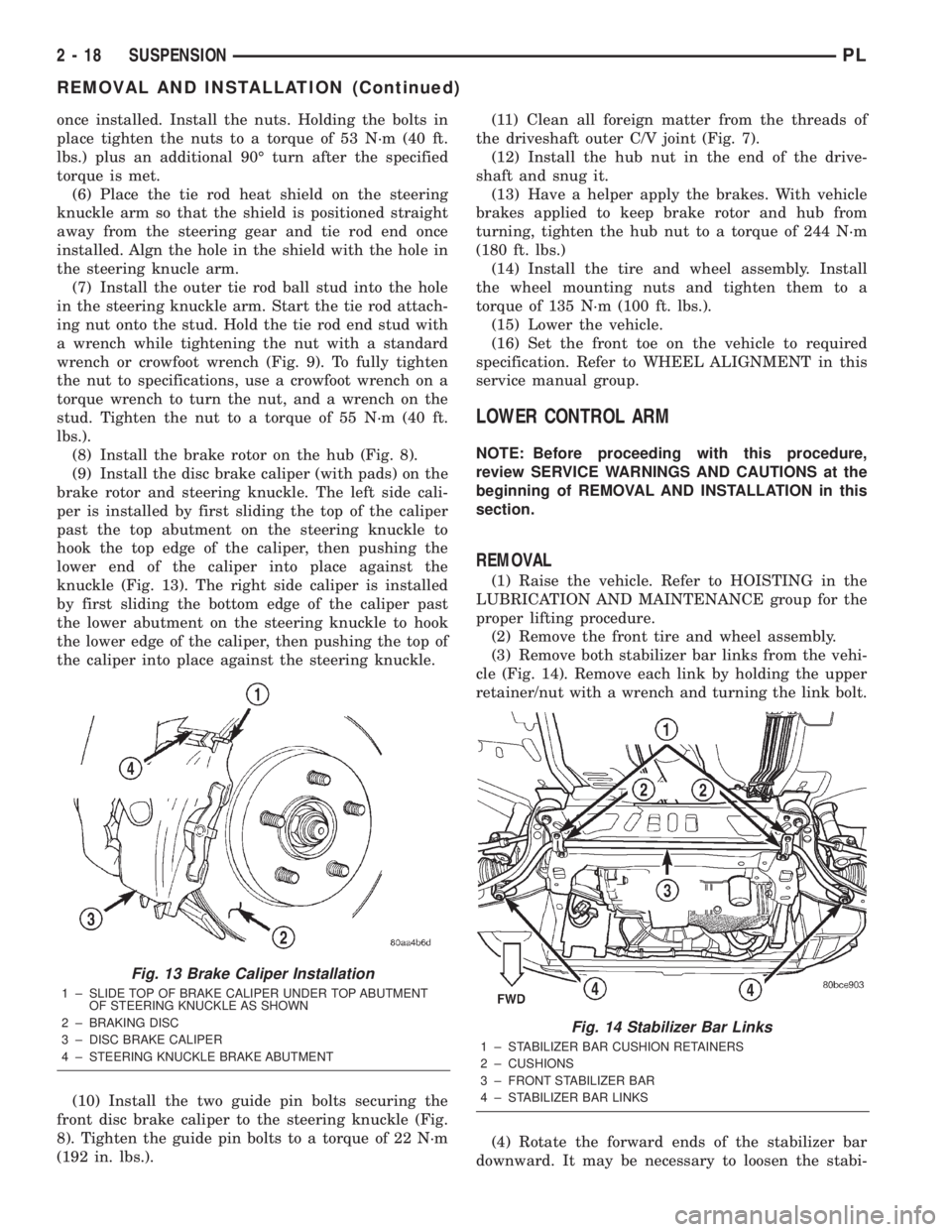
(8) Install the brake rotor on the hub (Fig. 8).
(9) Install the disc brake caliper (with pads) on the
brake rotor and steering knuckle. The left side cali-
per is installed by first sliding the top of the caliper
past the top abutment on the steering knuckle to
hook the top edge of the caliper, then pushing the
lower end of the caliper into place against the
knuckle (Fig. 13). The right side caliper is installed
by first sliding the bottom edge of the caliper past
the lower abutment on the steering knuckle to hook
the lower edge of the caliper, then pushing the top of
the caliper into place against the steering knuckle.
(10) Install the two guide pin bolts securing the
front disc brake caliper to the steering knuckle (Fig.
8). Tighten the guide pin bolts to a torque of 22 N´m
(192 in. lbs.).(11) Clean all foreign matter from the threads of
the driveshaft outer C/V joint (Fig. 7).
(12) Install the hub nut in the end of the drive-
shaft and snug it.
(13) Have a helper apply the brakes. With vehicle
brakes applied to keep brake rotor and hub from
turning, tighten the hub nut to a torque of 244 N´m
(180 ft. lbs.)
(14) Install the tire and wheel assembly. Install
the wheel mounting nuts and tighten them to a
torque of 135 N´m (100 ft. lbs.).
(15) Lower the vehicle.
(16) Set the front toe on the vehicle to required
specification. Refer to WHEEL ALIGNMENT in this
service manual group.
LOWER CONTROL ARM
NOTE: Before proceeding with this procedure,
review SERVICE WARNINGS AND CAUTIONS at the
beginning of REMOVAL AND INSTALLATION in this
section.
REMOVAL
(1) Raise the vehicle. Refer to HOISTING in the
LUBRICATION AND MAINTENANCE group for the
proper lifting procedure.
(2) Remove the front tire and wheel assembly.
(3) Remove both stabilizer bar links from the vehi-
cle (Fig. 14). Remove each link by holding the upper
retainer/nut with a wrench and turning the link bolt.
(4) Rotate the forward ends of the stabilizer bar
downward. It may be necessary to loosen the stabi-
Fig. 13 Brake Caliper Installation
1 ± SLIDE TOP OF BRAKE CALIPER UNDER TOP ABUTMENT
OF STEERING KNUCKLE AS SHOWN
2 ± BRAKING DISC
3 ± DISC BRAKE CALIPER
4 ± STEERING KNUCKLE BRAKE ABUTMENT
Fig. 14 Stabilizer Bar Links
1 ± STABILIZER BAR CUSHION RETAINERS
2 ± CUSHIONS
3 ± FRONT STABILIZER BAR
4 ± STABILIZER BAR LINKS
2 - 18 SUSPENSIONPL
REMOVAL AND INSTALLATION (Continued)
Page 33 of 1285
(2) Tighten the wheel mounting nut. This will pull
the wheel mounting stud into the flange of the hub.
When the head of the stud is fully seated against the
rear of the hub flange, remove the wheel mounting
nut and washers from the stud.
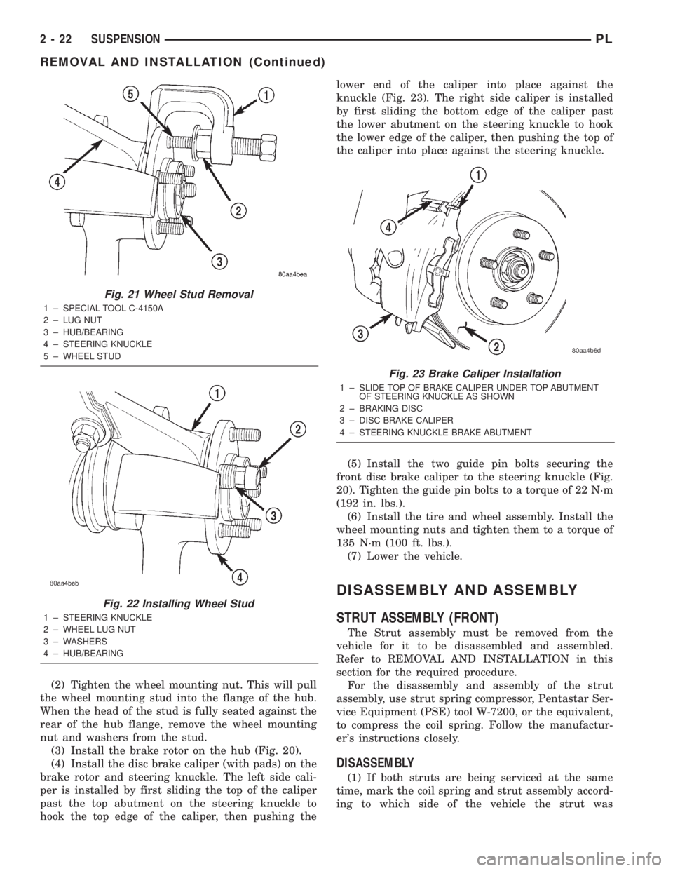
(3) Install the brake rotor on the hub (Fig. 20).
(4) Install the disc brake caliper (with pads) on the
brake rotor and steering knuckle. The left side cali-
per is installed by first sliding the top of the caliper
past the top abutment on the steering knuckle to
hook the top edge of the caliper, then pushing thelower end of the caliper into place against the
knuckle (Fig. 23). The right side caliper is installed
by first sliding the bottom edge of the caliper past
the lower abutment on the steering knuckle to hook
the lower edge of the caliper, then pushing the top of
the caliper into place against the steering knuckle.
(5) Install the two guide pin bolts securing the
front disc brake caliper to the steering knuckle (Fig.
20). Tighten the guide pin bolts to a torque of 22 N´m
(192 in. lbs.).
(6) Install the tire and wheel assembly. Install the
wheel mounting nuts and tighten them to a torque of
135 N´m (100 ft. lbs.).
(7) Lower the vehicle.
DISASSEMBLY AND ASSEMBLY
STRUT ASSEMBLY (FRONT)
The Strut assembly must be removed from the
vehicle for it to be disassembled and assembled.
Refer to REMOVAL AND INSTALLATION in this
section for the required procedure.
For the disassembly and assembly of the strut
assembly, use strut spring compressor, Pentastar Ser-
vice Equipment (PSE) tool W-7200, or the equivalent,
to compress the coil spring. Follow the manufactur-
er's instructions closely.
DISASSEMBLY
(1) If both struts are being serviced at the same
time, mark the coil spring and strut assembly accord-
ing to which side of the vehicle the strut was
Fig. 21 Wheel Stud Removal
1 ± SPECIAL TOOL C-4150A
2 ± LUG NUT
3 ± HUB/BEARING
4 ± STEERING KNUCKLE
5 ± WHEEL STUD
Fig. 22 Installing Wheel Stud
1 ± STEERING KNUCKLE
2 ± WHEEL LUG NUT
3 ± WASHERS
4 ± HUB/BEARING
Fig. 23 Brake Caliper Installation
1 ± SLIDE TOP OF BRAKE CALIPER UNDER TOP ABUTMENT
OF STEERING KNUCKLE AS SHOWN
2 ± BRAKING DISC
3 ± DISC BRAKE CALIPER
4 ± STEERING KNUCKLE BRAKE ABUTMENT
2 - 22 SUSPENSIONPL
REMOVAL AND INSTALLATION (Continued)
Page 83 of 1285
Proportioning valves balance front to rear braking
by controlling the brake fluid hydraulic pressure to
the rear brakes. Under light pedal application, the
proportioning valve allows normal fluid flow to the
rear brakes. Under higher pedal effort, the valve
reduces fluid pressure to the rear brakes.
The non-antilock master cylinder is a four-outlet
design with two screw-in proportioning valves
attached directly to the master cylinder housing (Fig.
3). One proportioning valve controls each rear brake.
BRAKE TUBES AND HOSES
The purpose of the brake tubes and flex hoses is to
transfer the pressurized brake fluid developed by the
master cylinder to the brakes at each wheel of the
vehicle. The flex hoses connect the chassis brake
tubes, which are mounted to the vehicle's underbody,
to the brake at each wheel, allowing for movement of
the vehicle's suspension. The brake tubes are steel
with a corrosion-resistant nylon coating applied to
the external surfaces. The flex hoses are made of
reinforced rubber.
DISC BRAKES (FRONT)
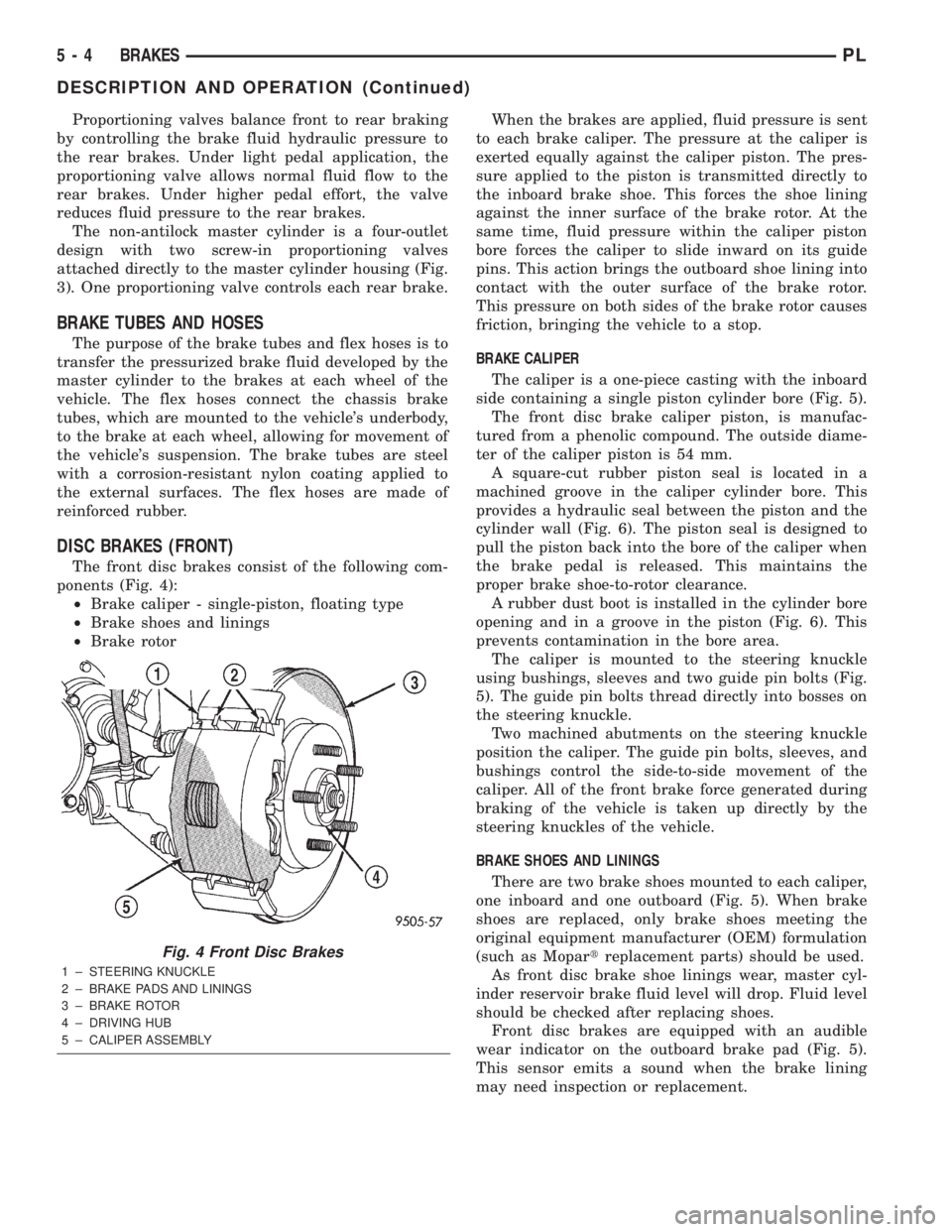
The front disc brakes consist of the following com-
ponents (Fig. 4):
²Brake caliper - single-piston, floating type
²Brake shoes and linings
²Brake rotorWhen the brakes are applied, fluid pressure is sent
to each brake caliper. The pressure at the caliper is
exerted equally against the caliper piston. The pres-
sure applied to the piston is transmitted directly to
the inboard brake shoe. This forces the shoe lining
against the inner surface of the brake rotor. At the
same time, fluid pressure within the caliper piston
bore forces the caliper to slide inward on its guide
pins. This action brings the outboard shoe lining into
contact with the outer surface of the brake rotor.
This pressure on both sides of the brake rotor causes
friction, bringing the vehicle to a stop.
BRAKE CALIPER
The caliper is a one-piece casting with the inboard
side containing a single piston cylinder bore (Fig. 5).
The front disc brake caliper piston, is manufac-
tured from a phenolic compound. The outside diame-
ter of the caliper piston is 54 mm.
A square-cut rubber piston seal is located in a
machined groove in the caliper cylinder bore. This
provides a hydraulic seal between the piston and the
cylinder wall (Fig. 6). The piston seal is designed to
pull the piston back into the bore of the caliper when
the brake pedal is released. This maintains the
proper brake shoe-to-rotor clearance.
A rubber dust boot is installed in the cylinder bore
opening and in a groove in the piston (Fig. 6). This
prevents contamination in the bore area.
The caliper is mounted to the steering knuckle
using bushings, sleeves and two guide pin bolts (Fig.
5). The guide pin bolts thread directly into bosses on
the steering knuckle.
Two machined abutments on the steering knuckle
position the caliper. The guide pin bolts, sleeves, and
bushings control the side-to-side movement of the
caliper. All of the front brake force generated during
braking of the vehicle is taken up directly by the
steering knuckles of the vehicle.
BRAKE SHOES AND LININGS
There are two brake shoes mounted to each caliper,
one inboard and one outboard (Fig. 5). When brake
shoes are replaced, only brake shoes meeting the
original equipment manufacturer (OEM) formulation
(such as Mopartreplacement parts) should be used.
As front disc brake shoe linings wear, master cyl-
inder reservoir brake fluid level will drop. Fluid level
should be checked after replacing shoes.
Front disc brakes are equipped with an audible
wear indicator on the outboard brake pad (Fig. 5).
This sensor emits a sound when the brake lining
may need inspection or replacement.
Fig. 4 Front Disc Brakes
1 ± STEERING KNUCKLE
2 ± BRAKE PADS AND LININGS
3 ± BRAKE ROTOR
4 ± DRIVING HUB
5 ± CALIPER ASSEMBLY
5 - 4 BRAKESPL
DESCRIPTION AND OPERATION (Continued)
Page 86 of 1285
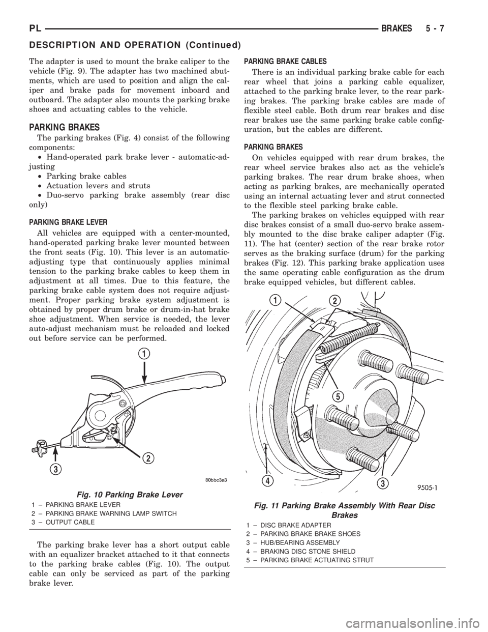
The adapter is used to mount the brake caliper to the
vehicle (Fig. 9). The adapter has two machined abut-
ments, which are used to position and align the cal-
iper and brake pads for movement inboard and
outboard. The adapter also mounts the parking brake
shoes and actuating cables to the vehicle.
PARKING BRAKES
The parking brakes (Fig. 4) consist of the following
components:
²Hand-operated park brake lever - automatic-ad-
justing
²Parking brake cables
²Actuation levers and struts
²Duo-servo parking brake assembly (rear disc
only)
PARKING BRAKE LEVER
All vehicles are equipped with a center-mounted,
hand-operated parking brake lever mounted between
the front seats (Fig. 10). This lever is an automatic-
adjusting type that continuously applies minimal
tension to the parking brake cables to keep them in
adjustment at all times. Due to this feature, the
parking brake cable system does not require adjust-
ment. Proper parking brake system adjustment is
obtained by proper drum brake or drum-in-hat brake
shoe adjustment. When service is needed, the lever
auto-adjust mechanism must be reloaded and locked
out before service can be performed.
The parking brake lever has a short output cable
with an equalizer bracket attached to it that connects
to the parking brake cables (Fig. 10). The output
cable can only be serviced as part of the parking
brake lever.PARKING BRAKE CABLES
There is an individual parking brake cable for each
rear wheel that joins a parking cable equalizer,
attached to the parking brake lever, to the rear park-
ing brakes. The parking brake cables are made of
flexible steel cable. Both drum rear brakes and disc
rear brakes use the same parking brake cable config-
uration, but the cables are different.
PARKING BRAKES
On vehicles equipped with rear drum brakes, the
rear wheel service brakes also act as the vehicle's
parking brakes. The rear drum brake shoes, when
acting as parking brakes, are mechanically operated
using an internal actuating lever and strut connected
to the flexible steel parking brake cable.
The parking brakes on vehicles equipped with rear
disc brakes consist of a small duo-servo brake assem-
bly mounted to the disc brake caliper adapter (Fig.
11). The hat (center) section of the rear brake rotor
serves as the braking surface (drum) for the parking
brakes (Fig. 12). This parking brake application uses
the same operating cable configuration as the drum
brake equipped vehicles, but different cables.
Fig. 10 Parking Brake Lever
1 ± PARKING BRAKE LEVER
2 ± PARKING BRAKE WARNING LAMP SWITCH
3 ± OUTPUT CABLEFig. 11 Parking Brake Assembly With Rear Disc
Brakes
1 ± DISC BRAKE ADAPTER
2 ± PARKING BRAKE BRAKE SHOES
3 ± HUB/BEARING ASSEMBLY
4 ± BRAKING DISC STONE SHIELD
5 ± PARKING BRAKE ACTUATING STRUT
PLBRAKES 5 - 7
DESCRIPTION AND OPERATION (Continued)