2000 DODGE NEON jump start
[x] Cancel search: jump startPage 2 of 1285
LUBRICATION AND MAINTENANCE
TABLE OF CONTENTS
page page
LUBRICANTS............................. 1
MAINTENANCE SCHEDULES................. 3JUMP STARTING, TOWING, AND HOISTING..... 7
LUBRICANTS
TABLE OF CONTENTS
page page
DESCRIPTION AND OPERATION
PARTS AND LUBRICANT
RECOMMENDATIONS....................1
CLASSIFICATION OF LUBRICANTS............1
INTERNATIONAL SYMBOLS.................2FLUID CHECK/FILL POINTS AND
LUBRICATION LOCATIONS.................2
LUBRICATION POINT LOCATIONS............2
SPECIFICATIONS
FLUID CAPACITIES........................2
DESCRIPTION AND OPERATION
PARTS AND LUBRICANT RECOMMENDATIONS
When service is required, DaimlerChrysler Corpo-
ration recommends that only Mopartbrand parts,
lubricants and chemicals be used. Mopar provides
the best engineered products for servicing
DaimlerChrysler Corporation vehicles.
CLASSIFICATION OF LUBRICANTS
DESCRIPTION
Only lubricants bearing designations defined by
the following organization should be used to service a
DaimlerChrysler Corporation vehicle.
²Society of Automotive Engineers (SAE)
²American Petroleum Institute (API) (Fig. 1)
²National Lubricating Grease Institute (NLGI)
(Fig. 2)
SAE VISCOSITY RATING
An SAE viscosity grade is used to specify the vis-
cosity of engine oil. These are specified with a dual
SAE viscosity grade which indicates the cold-to-hot
temperature viscosity range. Example SAE 5W-30 =
multiple grade engine oil.DaimlerChrysler Corporation only recommends
multiple grade engine oils.
API QUALITY CLASSIFICATION
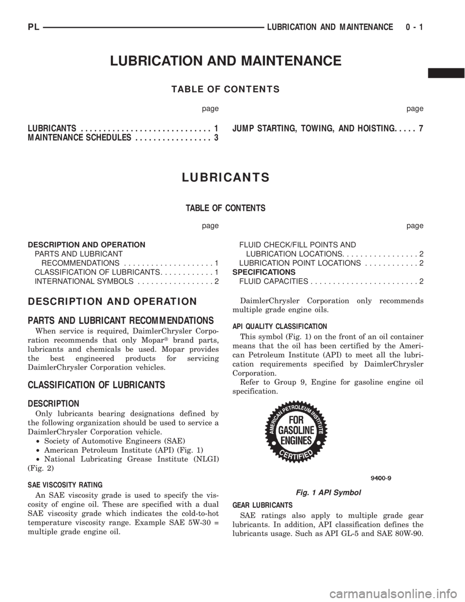
This symbol (Fig. 1) on the front of an oil container
means that the oil has been certified by the Ameri-
can Petroleum Institute (API) to meet all the lubri-
cation requirements specified by DaimlerChrysler
Corporation.
Refer to Group 9, Engine for gasoline engine oil
specification.
GEAR LUBRICANTS
SAE ratings also apply to multiple grade gear
lubricants. In addition, API classification defines the
lubricants usage. Such as API GL-5 and SAE 80W-90.
Fig. 1 API Symbol
PLLUBRICATION AND MAINTENANCE 0 - 1
Page 8 of 1285

JUMP STARTING, TOWING, AND HOISTING
TABLE OF CONTENTS
page page
DESCRIPTION AND OPERATION
JUMP STARTING PROCEDURE...............7
TOWING RECOMMENDATIONS...............7
HOISTING RECOMMENDATIONS.............7SERVICE PROCEDURES
JUMP STARTING PROCEDURE...............7
TOWING RECOMMENDATIONS...............8
HOISTING RECOMMENDATIONS.............9
DESCRIPTION AND OPERATION
JUMP STARTING PROCEDURE
Describes the procedure for starting a disable vehi-
cle.
TOWING RECOMMENDATIONS
Describes the recommended towing procedures.
HOISTING RECOMMENDATIONS
Describes the location of hoisting and jacking
points so that the vehicle can be lifted by a floor jack
or hoist.
SERVICE PROCEDURES
JUMP STARTING PROCEDURE
WARNING: REVIEW ALL SAFETY PRECAUTIONS
AND WARNINGS IN GROUP 8A, BATTERY/START-
ING/CHARGING SYSTEMS DIAGNOSTICS. DO NOT
JUMP START A FROZEN BATTERY, PERSONAL
INJURY CAN RESULT. DO NOT JUMP START WHEN
MAINTENANCE FREE BATTERY INDICATOR DOT IS
YELLOW OR BRIGHT COLOR. DO NOT JUMP
START A VEHICLE WHEN THE BATTERY FLUID IS
BELOW THE TOP OF LEAD PLATES. DO NOT
ALLOW JUMPER CABLE CLAMPS TO TOUCH
EACH OTHER WHEN CONNECTED TO A BOOSTER
SOURCE. DO NOT USE OPEN FLAME NEAR BAT-
TERY. REMOVE METALLIC JEWELRY WORN ON
HANDS OR WRISTS TO AVOID INJURY BY ACCI-
DENTAL ARCING OF BATTERY CURRENT. WHEN
USING A HIGH OUTPUT BOOSTING DEVICE, DO
NOT ALLOW BATTERY VOLTAGE TO EXCEED 16
VOLTS. REFER TO INSTRUCTIONS PROVIDED
WITH DEVICE BEING USED.
CAUTION: When using another vehicle as a
booster, do not allow vehicles to touch. Electrical
systems can be damaged on either vehicle.
TO JUMP START A DISABLED VEHICLE:
(1) Raise hood on disabled vehicle and visually
inspect engine compartment for:
²Battery cable clamp condition, clean if necessary.
²Frozen battery.
²Yellow or bright color test indicator, if equipped.
²Low battery fluid level.
²Generator drive belt condition and tension.
²Fuel fumes or leakage, correct if necessary.
CAUTION: If the cause of starting problem on dis-
abled vehicle is severe, damage to booster vehicle
charging system can result.
(2) When using another vehicle as a booster
source, park the booster vehicle within cable reach.
Turn off all accessories, set the parking brake, place
the automatic transmission in PARK or the manual
transmission in NEUTRAL and turn the ignition
OFF.
(3) On disabled vehicle, place gear selector in park
or neutral and set park brake. Turn off all accesso-
ries.
(4) Connect jumper cables to booster battery. RED
clamp to positive terminal (+). BLACK clamp to neg-
ative terminal (-). DO NOT allow clamps at opposite
end of cables to touch, electrical arc will result.
Review all warnings in this procedure.
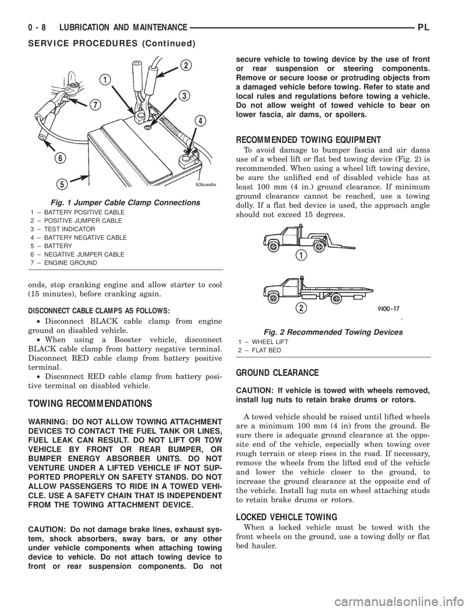
(5) On disabled vehicle, connect RED jumper cable
clamp to positive (+) terminal. Connect BLACK
jumper cable clamp to engine ground as close to the
ground cable attaching point as possible (Fig. 1).
(6) Start the engine in the vehicle which has the
booster battery, let the engine idle a few minutes,
then start the engine in the vehicle with the dis-
charged battery.
CAUTION: Do not crank starter motor on disabled
vehicle for more than 15 seconds, starter will over-
heat and could fail.
(7) Allow battery in disabled vehicle to charge to
at least 12.4 volts (75% charge) before attempting to
start engine. If engine does not start within 15 sec-
PLLUBRICATION AND MAINTENANCE 0 - 7
Page 9 of 1285
onds, stop cranking engine and allow starter to cool
(15 minutes), before cranking again.
DISCONNECT CABLE CLAMPS AS FOLLOWS:
²Disconnect BLACK cable clamp from engine
ground on disabled vehicle.
²When using a Booster vehicle, disconnect
BLACK cable clamp from battery negative terminal.
Disconnect RED cable clamp from battery positive
terminal.
²Disconnect RED cable clamp from battery posi-
tive terminal on disabled vehicle.
TOWING RECOMMENDATIONS
WARNING: DO NOT ALLOW TOWING ATTACHMENT
DEVICES TO CONTACT THE FUEL TANK OR LINES,
FUEL LEAK CAN RESULT. DO NOT LIFT OR TOW
VEHICLE BY FRONT OR REAR BUMPER, OR
BUMPER ENERGY ABSORBER UNITS. DO NOT
VENTURE UNDER A LIFTED VEHICLE IF NOT SUP-
PORTED PROPERLY ON SAFETY STANDS. DO NOT
ALLOW PASSENGERS TO RIDE IN A TOWED VEHI-
CLE. USE A SAFETY CHAIN THAT IS INDEPENDENT
FROM THE TOWING ATTACHMENT DEVICE.
CAUTION: Do not damage brake lines, exhaust sys-
tem, shock absorbers, sway bars, or any other
under vehicle components when attaching towing
device to vehicle. Do not attach towing device to
front or rear suspension components. Do notsecure vehicle to towing device by the use of front
or rear suspension or steering components.
Remove or secure loose or protruding objects from
a damaged vehicle before towing. Refer to state and
local rules and regulations before towing a vehicle.
Do not allow weight of towed vehicle to bear on
lower fascia, air dams, or spoilers.
RECOMMENDED TOWING EQUIPMENT
To avoid damage to bumper fascia and air dams
use of a wheel lift or flat bed towing device (Fig. 2) is
recommended. When using a wheel lift towing device,
be sure the unlifted end of disabled vehicle has at
least 100 mm (4 in.) ground clearance. If minimum
ground clearance cannot be reached, use a towing
dolly. If a flat bed device is used, the approach angle
should not exceed 15 degrees.
GROUND CLEARANCE
CAUTION: If vehicle is towed with wheels removed,
install lug nuts to retain brake drums or rotors.
A towed vehicle should be raised until lifted wheels
are a minimum 100 mm (4 in) from the ground. Be
sure there is adequate ground clearance at the oppo-
site end of the vehicle, especially when towing over
rough terrain or steep rises in the road. If necessary,
remove the wheels from the lifted end of the vehicle
and lower the vehicle closer to the ground, to
increase the ground clearance at the opposite end of
the vehicle. Install lug nuts on wheel attaching studs
to retain brake drums or rotors.
LOCKED VEHICLE TOWING
When a locked vehicle must be towed with the
front wheels on the ground, use a towing dolly or flat
bed hauler.
Fig. 1 Jumper Cable Clamp Connections
1 ± BATTERY POSITIVE CABLE
2 ± POSITIVE JUMPER CABLE
3 ± TEST INDICATOR
4 ± BATTERY NEGATIVE CABLE
5 ± BATTERY
6 ± NEGATIVE JUMPER CABLE
7 ± ENGINE GROUND
Fig. 2 Recommended Towing Devices
1 ± WHEEL LIFT
2 ± FLAT BED
0 - 8 LUBRICATION AND MAINTENANCEPL
SERVICE PROCEDURES (Continued)
Page 223 of 1285
DIAGNOSIS AND TESTING
CONTROL CIRCUIT
The starter control circuit has:
²Starter solenoid
²Starter relay
²Park/Neutral Starting and Back-Up Lamp
Switch with automatic transmissions
²Clutch Interlock/Upstop Switch with manual
transmissions
²Ignition switch
²Battery
²All related wiring and connections
²Double Start Override algorithm located in the
PCM
CAUTION: Before performing any starter tests, the
ignition and fuel systems must be disabled.
²To disable ignition and fuel systems, disconnect
the Automatic Shutdown Relay (ASD). The ASD relay
is located in the in the Power Distribution Center
(PDC). Refer to the PDC cover for the proper relay
location.
STARTER SOLENOID
WARNING: CHECK TO ENSURE THAT THE TRANS-
MISSION IS IN THE PARK POSITION WITH THE
PARKING BRAKE APPLIED
(1) Verify battery condition. Battery must be in
good condition with a full charge before performing
any starter tests. Refer to Battery Tests.
(2) Perform Starter Solenoid test BEFORE per-
forming the starter relay test.
(3) Raise the vehicle.
(4) Perform a visual inspection of the starter/
starter solenoid for corrosion, loose connections or
faulty wiring.
(5) Lower the vehicle.
(6) Locate and remove the starter relay from the
Power Distribution Center (PDC). Refer to the PDC
label for relay identification and location.
(7) Connect a starter switch or a jumper wire
between the remote battery positive post and termi-
nal 87 of the starter relay connector.
(a) If engine cranks, starter motor and starter
solenoid is good. Go to the Starter Relay Test.(b) If engine does not crank or solenoid chatters,
check wiring and connectors from starter relay to
starter solenoid for loose or corroded connections.
Check for corroded connections at starter termi-
nals.
(c) Repeat test. If engine still fails to crank prop-
erly, trouble is within starter or starter mounted
solenoid, and replace starter.
STARTER RELAY
WARNING: CHECK TO ENSURE THAT THE TRANS-
MISSION IS IN THE PARK POSITION WITH THE
PARKING BRAKE APPLIED.
RELAY TEST
The starter relay is located in the Power Distribu-
tion Center (PDC) in the engine compartment. Refer
to the PDC label for relay identification and location.
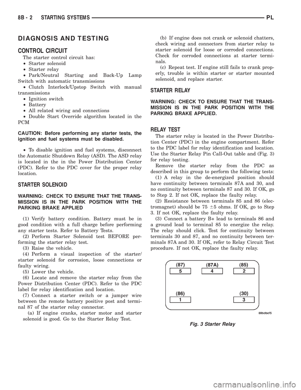
Use the Starter Relay Pin Call-Out table and (Fig. 3)
for relay testing.
Remove the starter relay from the PDC as
described in this group to perform the following tests:
(1) A relay in the de-energized position should
have continuity between terminals 87A and 30, and
no continuity between terminals 87 and 30. If OK, go
to Step 2. If not OK, replace the faulty relay.
(2) Resistance between terminals 85 and 86 (elec-
tromagnet) should be 7565 ohms. If OK, go to Step
3. If not OK, replace the faulty relay.
(3) Connect a battery B+ lead to terminals 86 and
a ground lead to terminal 85 to energize the relay.
The relay should click. Test for continuity between
terminals 30 and 87, and no continuity between ter-
minals 87A and 30. If OK, refer to Relay Circuit Test
procedure. If not OK, replace the faulty relay.
Fig. 3 Starter Relay
8B - 2 STARTING SYSTEMSPL
Page 383 of 1285
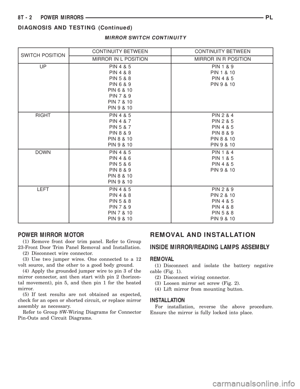
MIRROR SWITCH CONTINUITY
SWITCH POSITIONCONTINUITY BETWEEN CONTINUITY BETWEEN
MIRROR IN L POSITION MIRROR IN R POSITION
UP PIN4&5
PIN4&8
PIN5&8
PIN6&9
PIN6&10
PIN7&9
PIN7&10
PIN9&10PIN1&9
PIN1&10
PIN4&5
PIN9&10
RIGHT PIN4&5
PIN4&7
PIN5&7
PIN8&9
PIN8&10
PIN9&10PIN2&4
PIN2&5
PIN4&5
PIN8&9
PIN8&10
PIN9&10
DOWN PIN4&5
PIN4&6
PIN5&6
PIN8&9
PIN8&10
PIN9&10PIN1&4
PIN1&5
PIN4&5
PIN9&10
LEFT PIN4&5
PIN4&8
PIN5&8
PIN7&9
PIN7&10
PIN9&10PIN2&9
PIN2&10
PIN4&5
PIN4&8
PIN5&8
PIN9&10
POWER MIRROR MOTOR
(1) Remove front door trim panel. Refer to Group
23-Front Door Trim Panel Removal and Installation.
(2) Disconnect wire connector.
(3) Use two jumper wires. One connected to a 12
volt source, and the other to a good body ground.
(4) Apply the grounded jumper wire to pin 3 of the
mirror connector, ant then start with pin 2 (horizon-
tal movement), pin 5, and then pin 1 for the heated
mirror.
(5) If test results are not obtained as expected,
check for an open or shorted circuit, or replace mirror
assembly as necessary.
Refer to Group 8W-Wiring Diagrams for Connector
Pin-Outs and Circuit Diagrams.
REMOVAL AND INSTALLATION
INSIDE MIRROR/READING LAMPS ASSEMBLY
REMOVAL
(1) Disconnect and isolate the battery negative
cable (Fig. 1).
(2) Disconnect wiring connector.
(3) Loosen mirror set screw (Fig. 2).
(4) Lift mirror from mounting button.
INSTALLATION
For installation, reverse the above procedure.
Ensure the mirror is fully locked into place.
8T - 2 POWER MIRRORSPL
DIAGNOSIS AND TESTING (Continued)
Page 832 of 1285
being serviced. The plastic retainer will remain on
component being serviced after fitting is discon-
nected. The O-rings and spacer will remain in quick-
connect fitting connector body.
(5) Inspect quick-connect fitting body and compo-
nent for damage. Replace as necessary.
CAUTION:
When the quick-connect fitting was dis-
connected, the plastic retainer will remain on the com-
ponent being serviced. If this retainer must be
removed, very carefully release the retainer from the
component with two small screwdrivers. After removal,
inspect the retainer for cracks or any damage.
(6) Prior to connecting quick-connect fitting to
component being serviced, check condition of fitting
and component. Clean parts with a lint-free cloth.
Lubricate with clean engine oil.
(7) Insert quick-connect fitting to component being
serviced and into plastic retainer. When a connection
is made, a click will be heard.
(8) Verify a locked condition by firmly pulling on
fuel tube and fitting (15-30 lbs.).
(9) Connect negative cable to battery or auxiliary
jumper terminal.
(10) Start engine and check for leaks.
PLASTIC RETAINER RING TYPE FITTING
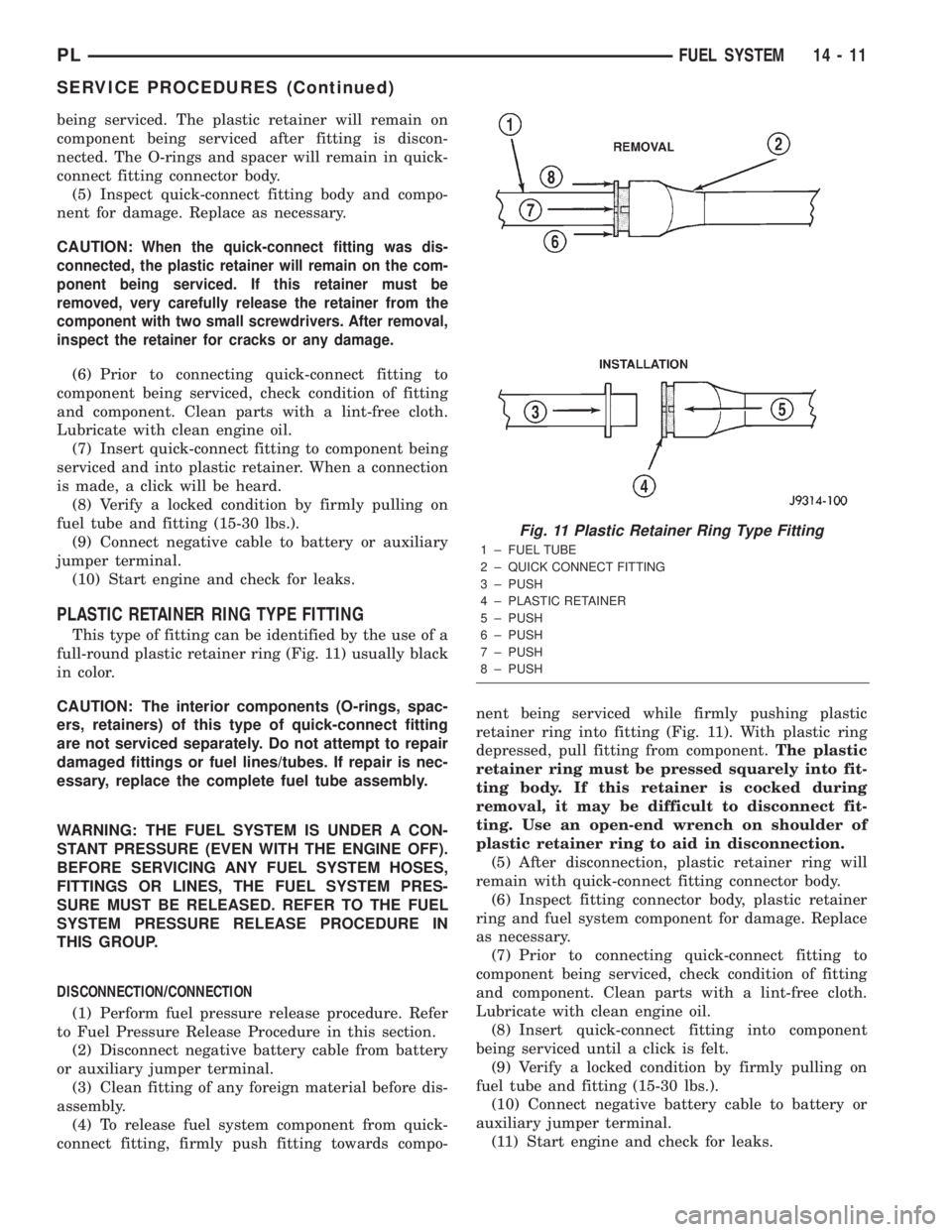
This type of fitting can be identified by the use of a
full-round plastic retainer ring (Fig. 11) usually black
in color.
CAUTION: The interior components (O-rings, spac-
ers, retainers) of this type of quick-connect fitting
are not serviced separately. Do not attempt to repair
damaged fittings or fuel lines/tubes. If repair is nec-
essary, replace the complete fuel tube assembly.
WARNING: THE FUEL SYSTEM IS UNDER A CON-
STANT PRESSURE (EVEN WITH THE ENGINE OFF).
BEFORE SERVICING ANY FUEL SYSTEM HOSES,
FITTINGS OR LINES, THE FUEL SYSTEM PRES-
SURE MUST BE RELEASED. REFER TO THE FUEL
SYSTEM PRESSURE RELEASE PROCEDURE IN
THIS GROUP.
DISCONNECTION/CONNECTION
(1) Perform fuel pressure release procedure. Refer
to Fuel Pressure Release Procedure in this section.
(2) Disconnect negative battery cable from battery
or auxiliary jumper terminal.
(3) Clean fitting of any foreign material before dis-
assembly.
(4) To release fuel system component from quick-
connect fitting, firmly push fitting towards compo-nent being serviced while firmly pushing plastic
retainer ring into fitting (Fig. 11). With plastic ring
depressed, pull fitting from component.The plastic
retainer ring must be pressed squarely into fit-
ting body. If this retainer is cocked during
removal, it may be difficult to disconnect fit-
ting. Use an open-end wrench on shoulder of
plastic retainer ring to aid in disconnection.
(5) After disconnection, plastic retainer ring will
remain with quick-connect fitting connector body.
(6) Inspect fitting connector body, plastic retainer
ring and fuel system component for damage. Replace
as necessary.
(7) Prior to connecting quick-connect fitting to
component being serviced, check condition of fitting
and component. Clean parts with a lint-free cloth.
Lubricate with clean engine oil.
(8) Insert quick-connect fitting into component
being serviced until a click is felt.
(9) Verify a locked condition by firmly pulling on
fuel tube and fitting (15-30 lbs.).
(10) Connect negative battery cable to battery or
auxiliary jumper terminal.
(11) Start engine and check for leaks.
Fig. 11 Plastic Retainer Ring Type Fitting
1 ± FUEL TUBE
2 ± QUICK CONNECT FITTING
3 ± PUSH
4 ± PLASTIC RETAINER
5 ± PUSH
6 ± PUSH
7 ± PUSH
8 ± PUSH
PLFUEL SYSTEM 14 - 11
SERVICE PROCEDURES (Continued)
Page 1084 of 1285
REMOVAL AND INSTALLATION
WHEEL COVER (LOCK-ON)
REMOVE
NOTE: When unthreading the wheel cover retaining
nuts (Fig. 12) from the wheel nuts it is recom-
mended that a hand wrench be used and not an
impact wrench. Use of an impact wrench could
result in damage to the lock-on wheel cover retain-
ing nuts.
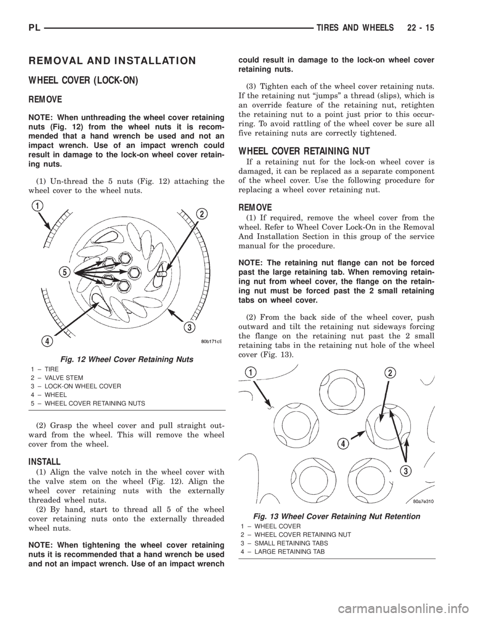
(1) Un-thread the 5 nuts (Fig. 12) attaching the
wheel cover to the wheel nuts.
(2) Grasp the wheel cover and pull straight out-
ward from the wheel. This will remove the wheel
cover from the wheel.
INSTALL
(1) Align the valve notch in the wheel cover with
the valve stem on the wheel (Fig. 12). Align the
wheel cover retaining nuts with the externally
threaded wheel nuts.
(2) By hand, start to thread all 5 of the wheel
cover retaining nuts onto the externally threaded
wheel nuts.
NOTE: When tightening the wheel cover retaining
nuts it is recommended that a hand wrench be used
and not an impact wrench. Use of an impact wrenchcould result in damage to the lock-on wheel cover
retaining nuts.
(3) Tighten each of the wheel cover retaining nuts.
If the retaining nut ªjumpsº a thread (slips), which is
an override feature of the retaining nut, retighten
the retaining nut to a point just prior to this occur-
ring. To avoid rattling of the wheel cover be sure all
five retaining nuts are correctly tightened.
WHEEL COVER RETAINING NUT
If a retaining nut for the lock-on wheel cover is
damaged, it can be replaced as a separate component
of the wheel cover. Use the following procedure for
replacing a wheel cover retaining nut.
REMOVE
(1) If required, remove the wheel cover from the
wheel. Refer to Wheel Cover Lock-On in the Removal
And Installation Section in this group of the service
manual for the procedure.
NOTE: The retaining nut flange can not be forced
past the large retaining tab. When removing retain-
ing nut from wheel cover, the flange on the retain-
ing nut must be forced past the 2 small retaining
tabs on wheel cover.
(2) From the back side of the wheel cover, push
outward and tilt the retaining nut sideways forcing
the flange on the retaining nut past the 2 small
retaining tabs in the retaining nut hole of the wheel
cover (Fig. 13).
Fig. 12 Wheel Cover Retaining Nuts
1 ± TIRE
2 ± VALVE STEM
3 ± LOCK-ON WHEEL COVER
4 ± WHEEL
5 ± WHEEL COVER RETAINING NUTS
Fig. 13 Wheel Cover Retaining Nut Retention
1 ± WHEEL COVER
2 ± WHEEL COVER RETAINING NUT
3 ± SMALL RETAINING TABS
4 ± LARGE RETAINING TAB
PLTIRES AND WHEELS 22 - 15
Page 1086 of 1285
(3) Grasp the wheel cover and pull straight out-
ward. This will remove the wheel cover from the
wheel.
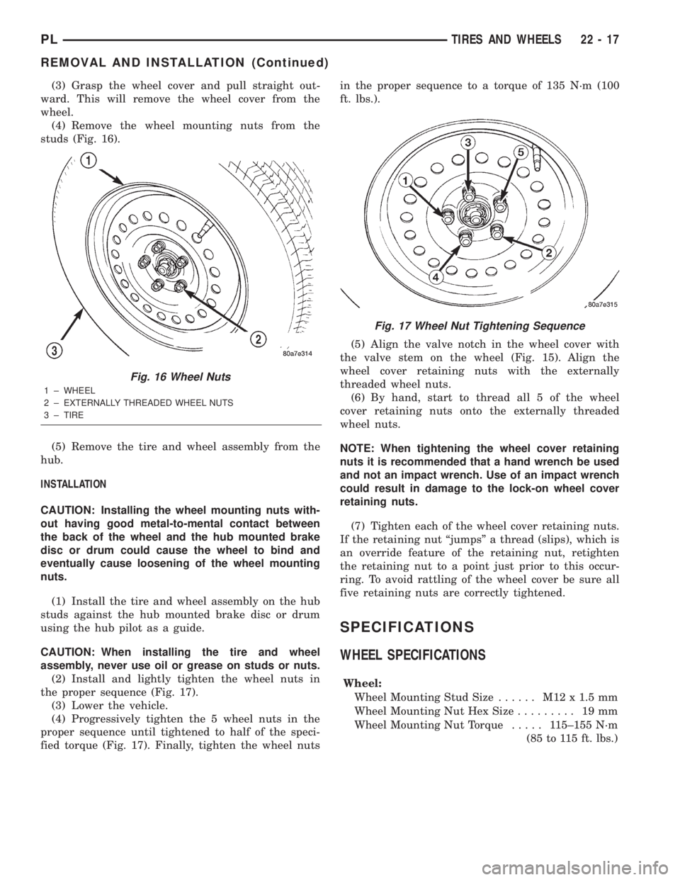
(4) Remove the wheel mounting nuts from the
studs (Fig. 16).
(5) Remove the tire and wheel assembly from the
hub.
INSTALLATION
CAUTION: Installing the wheel mounting nuts with-
out having good metal-to-mental contact between
the back of the wheel and the hub mounted brake
disc or drum could cause the wheel to bind and
eventually cause loosening of the wheel mounting
nuts.
(1) Install the tire and wheel assembly on the hub
studs against the hub mounted brake disc or drum
using the hub pilot as a guide.
CAUTION: When installing the tire and wheel
assembly, never use oil or grease on studs or nuts.
(2) Install and lightly tighten the wheel nuts in
the proper sequence (Fig. 17).
(3) Lower the vehicle.
(4) Progressively tighten the 5 wheel nuts in the
proper sequence until tightened to half of the speci-
fied torque (Fig. 17). Finally, tighten the wheel nutsin the proper sequence to a torque of 135 N´m (100
ft. lbs.).
(5) Align the valve notch in the wheel cover with
the valve stem on the wheel (Fig. 15). Align the
wheel cover retaining nuts with the externally
threaded wheel nuts.
(6) By hand, start to thread all 5 of the wheel
cover retaining nuts onto the externally threaded
wheel nuts.
NOTE: When tightening the wheel cover retaining
nuts it is recommended that a hand wrench be used
and not an impact wrench. Use of an impact wrench
could result in damage to the lock-on wheel cover
retaining nuts.
(7) Tighten each of the wheel cover retaining nuts.
If the retaining nut ªjumpsº a thread (slips), which is
an override feature of the retaining nut, retighten
the retaining nut to a point just prior to this occur-
ring. To avoid rattling of the wheel cover be sure all
five retaining nuts are correctly tightened.
SPECIFICATIONS
WHEEL SPECIFICATIONS
Wheel:
Wheel Mounting Stud Size...... M12x1.5mm
Wheel Mounting Nut Hex Size......... 19mm
Wheel Mounting Nut Torque..... 115±155 N´m
(85 to 115 ft. lbs.)
Fig. 16 Wheel Nuts
1 ± WHEEL
2 ± EXTERNALLY THREADED WHEEL NUTS
3 ± TIRE
Fig. 17 Wheel Nut Tightening Sequence
PLTIRES AND WHEELS 22 - 17
REMOVAL AND INSTALLATION (Continued)