2000 DODGE NEON fuses
[x] Cancel search: fusesPage 147 of 1285
CONTROLLER ANTILOCK BRAKE INPUTS
²wheel speed sensors (four)
²stop lamp switch
²ignition switch
²system relay voltage
²ground
²traction control lamp
²diagnostic communication (PCI)
CONTROLLER ANTILOCK BRAKE OUTPUTS
²amber ABS warning lamp actuation (through
MIC)
²red BRAKE warning lamp actuation (through
MIC)
²traction control lamp actuation (through MIC)
²diagnostic communication. (PCI)
HYDRAULIC CONTROL UNIT (HCU)
The hydraulic control unit (HCU) is mounted to
the CAB as part of the ICU (Fig. 2). The HCU con-
trols the flow of brake fluid to the brakes using a
series of valves and accumulators. A pump/motor is
mounted on the HCU to supply build pressure to the
brakes during an ABS stop.
VALVES AND SOLENOIDS
The valve block contains four inlet valves and four
outlet solenoid valves. The inlet valves are spring-
loaded in the open position and the outlet valves are
spring-loaded in the closed position during normal
braking. The fluid is allowed to flow from the master
cylinder to the wheel brakes.
During an ABS stop, these valves cycle to maintain
the proper slip ratio for each wheel. The inlet valve
closes preventing further pressure increase and the
outlet valve opens to provide a path from the wheel
brake to the HCU accumulators and pump/motor.
This releases (decays) pressure from the wheel brake,
thus releasing the wheel from excessive slippage.
Once the wheel is no longer slipping, the outlet valve
is closed and the inlet valve is opened to reapply
(build) pressure.
There are four other valves in the HCU. These four
remaining valves are used for traction control. Two
traction control (TC) valves, mounted in the HCU
valve block, are normally in the open position and
close only when the traction control is applied. There
are also two shuttle valves which control pressure
return to the master cylinder under ABS and traction
control conditions.
These TC valves are used to isolate the rear (non-
driving) wheels of the vehicle from the hydraulic
pressure that the HCU pump/motor is sending to the
front (driving) wheels when traction control is being
applied. The rear brakes need to be isolated from the
master cylinder when traction control is beingapplied so the rear wheels do not drag. For more
information on the TC and shuttle valves, see TRAC-
TION CONTROL SYSTEM in this section.
BRAKE FLUID ACCUMULATORS
There are two fluid accumulators in the HCU: one
for the primary hydraulic circuit, and one for the sec-
ondary hydraulic circuit. Each hydraulic circuit uses
a 3 cc accumulator.
The fluid accumulators temporarily store brake
fluid that is removed from the wheel brakes during
an ABS cycle. This stored fluid is used by the pump/
motor to provide build pressure for the brake hydrau-
lic system. When the antilock stop is complete, the
accumulators are drained by the pump/motor.
There are two noise dampening chambers in the
HCU on this vehicle equipped with traction control.
PUMP/MOTOR
There are two pump assemblies in the HCU: one
for the primary hydraulic circuit, and one for the sec-
ondary hydraulic circuit. Both pumps are driven by a
common electric motor (Fig. 2). This DC-type motor
is integral to the HCU and is controlled by the CAB.
The pump/motor provides the extra amount of
brake fluid needed during antilock braking. Brake
fluid is released to the accumulators when the outlet
valve is opened during an antilock stop. The pump
mechanism consists of two opposing pistons operated
by an eccentric camshaft. In operation, these pistons
are used to purge fluid from the accumulators back
into the master cylinder circuits. When the antilock
stop is complete, the pump/motor drains the accumu-
lators.
The pump motor is also used to build pressure
when the system goes into traction control mode. For
more information, refer to TRACTION CONTROL
SYSTEM in this section.
The CAB may turn on the pump/motor when an
antilock stop is detected. The pump/motor continues
to run during the antilock stop and is turned off after
the stop is complete. Under some conditions, the
pump/motor runs to drain the accumulators during
the next drive-off.
The pump/motor is not a serviceable item; if it
requires replacement, the HCU must be replaced.
ABS FUSES
The ABS fuse and the ABS pump/motor fuse are
located in the power distribution center (PDC). Refer
to the sticker on the inside of the PDC cover for the
location of these fuses. The PDC is located on the
driver's side of the engine compartment between the
back of the battery and the brake master cylinder.
The CAB fuse can be found in the fuse junction
block under the instrument panel.
5 - 68 BRAKESPL
DESCRIPTION AND OPERATION (Continued)
Page 153 of 1285
DIAGNOSIS AND TESTING
SERVICE WARNINGS AND CAUTIONS
The ABS uses an electronic control module, the
CAB. This module is designed to withstand normal
current draws associated with vehicle operation.
Care must be taken to avoid overloading the CAB
circuits.
CAUTION: In testing for open or short circuits, do
not ground or apply voltage to any of the circuits
unless instructed to do so for a diagnostic proce-
dure.
CAUTION: These circuits should only be tested
using a high impedance multi-meter or the DRB
scan tool as described in this section. Power
should never be removed or applied to any control
module with the ignition in the ON position. Before
removing or connecting battery cables, fuses, or
connectors, always turn the ignition to the OFF
position.
CAUTION: Use only factory wiring harnesses. Do
not cut or splice wiring to the brake circuits. The
addition of after-market electrical equipment (car
phone, radar detector, citizen band radio, trailer
lighting, trailer brakes, etc.) on a vehicle equipped
with antilock brakes may affect the function of the
antilock brake system.
ABS GENERAL DIAGNOSTICS INFORMATION
This section contains information necessary to
diagnose the antilock brake system. Specifically, this
section should be used to help diagnose conditions
which result in any of the following:
(1) amber ABS warning lamp turned on.
(2) brakes lock-up on hard application.
Diagnosis of base brake conditions that are obvi-
ously mechanical in nature should be directed to
BASE BRAKE SYSTEM at the beginning of this
group.
Many ABS conditions judged to be a problem by
the driver may be normal operating conditions. See
ABS OPERATION in the DESCRIPTION AND
OPERATION section of this group to become famil-
iarized with the normal characteristics of this
antilock brake system.
ABS WIRING DIAGRAM INFORMATION
During the diagnosis and testing of the antilock
brake system it may become necessary to reference
the wiring diagrams covering the antilock brake sys-
tem and its components. For wiring diagrams refer to
GROUP 8W of this service manual. It will provide
you with the wiring diagrams and the circuit descrip-
tion and operation information covering the antilock
brake system.
ABS VEHICLE TEST DRIVE
Most ABS complaints will require a test drive to
properly duplicate and diagnose the condition.
WARNING: CONDITIONS THAT RESULT IN TURN-
ING ON THE RED BRAKE WARNING LAMP MAY
INDICATE REDUCED BRAKING ABILITY.
Before test driving a brake complaint vehicle, note
whether the red BRAKE warning lamp, amber ABS
warning lamp, or both are turned on. If it is the red
BRAKE warning lamp, there is a brake hydraulic
problem that must be corrected before driving the
vehicle. Refer to the BASE BRAKE SYSTEM for
diagnosis of the red BRAKE warning lamp. If the red
brake warning lamp is illuminated, there is also a
possibility that there is an ABS problem and the
amber ABS warning lamp is not able to illuminate,
so the MIC turns on the red Brake warning lamp by
default.
If the amber ABS warning lamp is on, test drive
the vehicle as described below. While the amber ABS
warning lamp is on, the ABS is not functional. The
ability to stop the car using the base brake system
should not be affected.
If a functional problem of the ABS is determined
while test driving the vehicle, refer to the Chassis
Diagnostic Procedures manual.
(1) Turn the key to the OFF position and then
back to the ON position. Note whether the amber
ABS warning lamp continues to stay on. If it does,
refer to the diagnostic manual.
(2) If the amber ABS warning lamp goes out, shift
into gear and drive the car to a speed of 20 kph (12
mph) to complete the ABS start-up and drive-off
cycles (see ABS ELECTRONIC DIAGNOSIS). If at
this time the amber ABS warning lamp comes on,
refer to the diagnostic manual.
(3) If the amber ABS warning lamp remains out,
drive the vehicle a short distance. Accelerate the
vehicle to a speed of at least 40 mph. Bring the vehi-
cle to a complete stop, braking hard enough to cause
the ABS to cycle. Again accelerate the vehicle past 25
mph. Refer to the diagnostic manual for further test-
ing of the antilock brake system.
5 - 74 BRAKESPL
Page 154 of 1285
ABS ELECTRONIC DIAGNOSIS
The following information is presented to give the
technician a general background on the diagnostic
capabilities of the ABS system. Complete electronic
diagnosis of the ABS system used on this vehicle is
covered in the Chassis Diagnostic Procedures manual.
Electronic diagnosis of the ABS system used on
this vehicle is performed using the DRBIIItscan
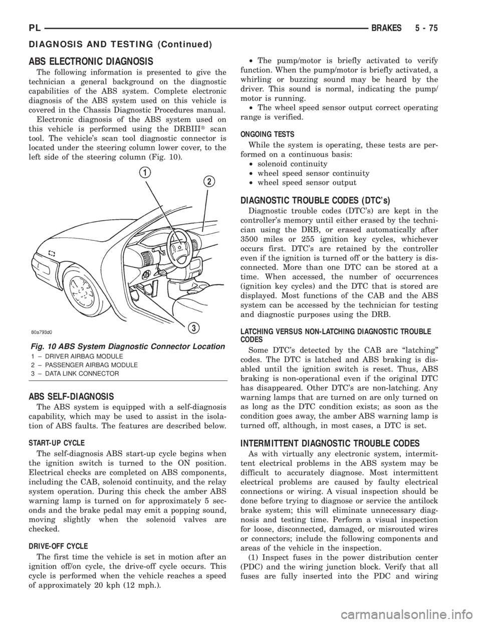
tool. The vehicle's scan tool diagnostic connector is
located under the steering column lower cover, to the
left side of the steering column (Fig. 10).
ABS SELF-DIAGNOSIS
The ABS system is equipped with a self-diagnosis
capability, which may be used to assist in the isola-
tion of ABS faults. The features are described below.
START-UP CYCLE
The self-diagnosis ABS start-up cycle begins when
the ignition switch is turned to the ON position.
Electrical checks are completed on ABS components,
including the CAB, solenoid continuity, and the relay
system operation. During this check the amber ABS
warning lamp is turned on for approximately 5 sec-
onds and the brake pedal may emit a popping sound,
moving slightly when the solenoid valves are
checked.
DRIVE-OFF CYCLE
The first time the vehicle is set in motion after an
ignition off/on cycle, the drive-off cycle occurs. This
cycle is performed when the vehicle reaches a speed
of approximately 20 kph (12 mph.).²The pump/motor is briefly activated to verify
function. When the pump/motor is briefly activated, a
whirling or buzzing sound may be heard by the
driver. This sound is normal, indicating the pump/
motor is running.
²The wheel speed sensor output correct operating
range is verified.
ONGOING TESTS
While the system is operating, these tests are per-
formed on a continuous basis:
²solenoid continuity
²wheel speed sensor continuity
²wheel speed sensor output
DIAGNOSTIC TROUBLE CODES (DTC's)
Diagnostic trouble codes (DTC's) are kept in the
controller's memory until either erased by the techni-
cian using the DRB, or erased automatically after
3500 miles or 255 ignition key cycles, whichever
occurs first. DTC's are retained by the controller
even if the ignition is turned off or the battery is dis-
connected. More than one DTC can be stored at a
time. When accessed, the number of occurrences
(ignition key cycles) and the DTC that is stored are
displayed. Most functions of the CAB and the ABS
system can be accessed by the technician for testing
and diagnostic purposes using the DRB.
LATCHING VERSUS NON-LATCHING DIAGNOSTIC TROUBLE
CODES
Some DTC's detected by the CAB are ªlatchingº
codes. The DTC is latched and ABS braking is dis-
abled until the ignition switch is reset. Thus, ABS
braking is non-operational even if the original DTC
has disappeared. Other DTC's are non-latching. Any
warning lamps that are turned on are only turned on
as long as the DTC condition exists; as soon as the
condition goes away, the amber ABS warning lamp is
turned off, although, in most cases, a DTC is set.
INTERMITTENT DIAGNOSTIC TROUBLE CODES
As with virtually any electronic system, intermit-
tent electrical problems in the ABS system may be
difficult to accurately diagnose. Most intermittent
electrical problems are caused by faulty electrical
connections or wiring. A visual inspection should be
done before trying to diagnose or service the antilock
brake system; this will eliminate unnecessary diag-
nosis and testing time. Perform a visual inspection
for loose, disconnected, damaged, or misrouted wires
or connectors; include the following components and
areas of the vehicle in the inspection.
(1) Inspect fuses in the power distribution center
(PDC) and the wiring junction block. Verify that all
fuses are fully inserted into the PDC and wiring
Fig. 10 ABS System Diagnostic Connector Location
1 ± DRIVER AIRBAG MODULE
2 ± PASSENGER AIRBAG MODULE
3 ± DATA LINK CONNECTOR
PLBRAKES 5 - 75
DIAGNOSIS AND TESTING (Continued)
Page 155 of 1285
junction block. A label on the underside of the PDC
cover identifies the locations of the ABS fuses.
(2) Inspect the 25-way electrical connector at the
CAB for damaged, spread, or backed-out wiring ter-
minals. Verify that the 25-way connector is fully
inserted in the socket of the CAB. Be sure that wires
are not stretched tight or pulled out of the connector.
(3) Verify that all the wheel speed sensor connec-
tions are secure.
(4) Look for poor mating of connector halves or ter-
minals not fully seated in the connector body.
(5)
Check for improperly formed or damaged termi-
nals. All connector terminals in a suspect circuit should
be carefully reformed to increase contact tension.
(6) Look for poor terminal-to-wire connections.
This requires removing the terminal from the connec-
tor body to inspect it.
(7) Verify pin presence in the connector assembly
(8) Check for proper ground connections. Check all
ground connections for signs of corrosion, loose fas-
teners, or other potential defects. Refer to the wiring
diagrams for ground locations.
(9) Look for problems with the main power sources
of the vehicle. Inspect the battery, generator, ignition
circuits and other related relays and fuses.
If a visual check does not find the cause of the
problem, operate the car in an attempt to duplicate
the condition and record any trouble codes.
Most failures of the ABS disable the ABS function
for the entire ignition cycle even if the fault clears
before key-off. There are some failure conditions,
however, that allow ABS operation to resume during
the ignition cycle in which the trouble occurred even
if the trouble conditions are no longer present.
The following trouble conditions may result in
intermittent illumination of the amber ABS warning
lamp.
²Low system voltage. If Low System Voltage is
detected by the CAB, the CAB will turn on the ABS
Warning Lamp until normal system voltage is
achieved. Once normal voltage is seen at the CAB,
normal operation resumes.
²High system voltage. If high system voltage is
detected by the CAB, the CAB will turn on the
Amber ABS Warning Lamp until normal system volt-
age is achieved. Once normal voltage is again
detected by the CAB, normal ABS operation resumes.
Additional possible causes that may result in the
illumination of the amber ABS warning lamp are as
follows:
²Any condition that interrupts electrical current
to the CAB may cause the amber ABS warning lamp
to turn on intermittently.
²If PCI communication between the body control-
ler and the CAB is interrupted, the body controller
can turn on the amber ABS warning lamp.
TONE WHEEL
Tone wheels can cause erratic wheel speed sensor
signals. Inspect tone wheels for the following possible
causes:
²missing, chipped, or broken teeth
²contact with the wheel speed sensor
²wheel speed sensor to tone wheel alignment
²wheel speed sensor to tone wheel clearance
²excessive tone wheel runout
²tone wheel loose on its mounting surface
If a front tone wheel is found to need replacement,
the drive shaft must be replaced. No attempt should
be made to replace just the tone wheel. Refer to the
DIFFERENTIAL AND DRIVELINE group in this
service manual for removal and installation.
If a rear tone wheel is found to need replacement,
the rear hub and bearing must be replaced. No
attempt should be made to replace just the tone
wheel. Refer to the SUSPENSION group in this ser-
vice manual for removal and installation.
If wheel speed sensor to tone wheel contact is evi-
dent, determine the cause and correct it before
replacing the wheel speed sensor or tone wheel.
Check the gap between the speed sensor head and
the tone wheel to ensure it is within specifications.
Refer to SPECIFICATIONS in this section of the ser-
vice manual for the minimum and maximum wheel
speed sensor to tone wheel clearance.
Excessive wheel speed sensor runout can cause
erratic wheel speed sensor signals. Refer to SPECI-
FICATIONS in this section of the service manual for
the maximum allowed tone wheel runout. If tone
wheel runout is excessive, determine if it is caused
by a defect in the driveshaft assembly or hub and
bearing. Replace as necessary.
Tone wheels are pressed onto their mounting sur-
faces and should not rotate independently from the
mounting surface. Replacement of the front drive-
shaft or rear hub and bearing is necessary.
BRAKE FLUID CONTAMINATION
Indications of fluid contamination are swollen or
deteriorated rubber parts. Swelling indicates the
presence of petroleum in the brake fluid.
To test for contamination, put a small amount of
drained brake fluid in clear glass jar. If the fluid sep-
arates into layers, there is mineral oil or other fluid
contamination of the brake fluid.
If the brake fluid is contaminated, drain and thor-
oughly flush the brake system. Replace all the rubber
parts or components containing rubber coming into
contact with the brake fluid including: the master
cylinder; proportioning valves; caliper seals; wheel
cylinder seals; ABS hydraulic control unit; and all
hydraulic fluid hoses.
5 - 76 BRAKESPL
DIAGNOSIS AND TESTING (Continued)
Page 214 of 1285
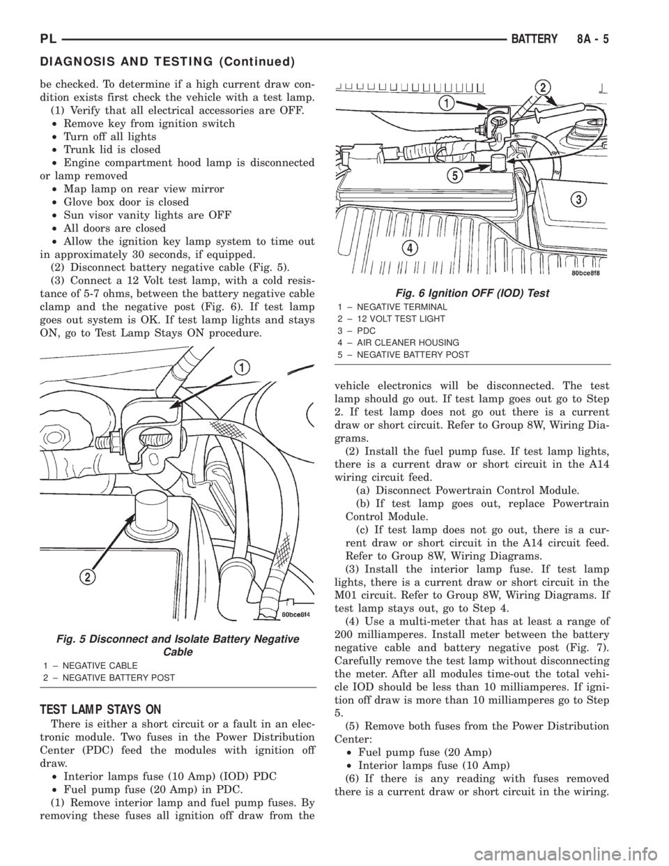
be checked. To determine if a high current draw con-
dition exists first check the vehicle with a test lamp.
(1) Verify that all electrical accessories are OFF.
²Remove key from ignition switch
²Turn off all lights
²Trunk lid is closed
²Engine compartment hood lamp is disconnected
or lamp removed
²Map lamp on rear view mirror
²Glove box door is closed
²Sun visor vanity lights are OFF
²All doors are closed
²Allow the ignition key lamp system to time out
in approximately 30 seconds, if equipped.
(2) Disconnect battery negative cable (Fig. 5).
(3) Connect a 12 Volt test lamp, with a cold resis-
tance of 5-7 ohms, between the battery negative cable
clamp and the negative post (Fig. 6). If test lamp
goes out system is OK. If test lamp lights and stays
ON, go to Test Lamp Stays ON procedure.
TEST LAMP STAYS ON
There is either a short circuit or a fault in an elec-
tronic module. Two fuses in the Power Distribution
Center (PDC) feed the modules with ignition off
draw.
²Interior lamps fuse (10 Amp) (IOD) PDC
²Fuel pump fuse (20 Amp) in PDC.
(1) Remove interior lamp and fuel pump fuses. By
removing these fuses all ignition off draw from thevehicle electronics will be disconnected. The test
lamp should go out. If test lamp goes out go to Step
2. If test lamp does not go out there is a current
draw or short circuit. Refer to Group 8W, Wiring Dia-
grams.
(2) Install the fuel pump fuse. If test lamp lights,
there is a current draw or short circuit in the A14
wiring circuit feed.
(a) Disconnect Powertrain Control Module.
(b) If test lamp goes out, replace Powertrain
Control Module.
(c) If test lamp does not go out, there is a cur-
rent draw or short circuit in the A14 circuit feed.
Refer to Group 8W, Wiring Diagrams.
(3) Install the interior lamp fuse. If test lamp
lights, there is a current draw or short circuit in the
M01 circuit. Refer to Group 8W, Wiring Diagrams. If
test lamp stays out, go to Step 4.
(4) Use a multi-meter that has at least a range of
200 milliamperes. Install meter between the battery
negative cable and battery negative post (Fig. 7).
Carefully remove the test lamp without disconnecting
the meter. After all modules time-out the total vehi-
cle IOD should be less than 10 milliamperes. If igni-
tion off draw is more than 10 milliamperes go to Step
5.
(5) Remove both fuses from the Power Distribution
Center:
²Fuel pump fuse (20 Amp)
²Interior lamps fuse (10 Amp)
(6) If there is any reading with fuses removed
there is a current draw or short circuit in the wiring.
Fig. 5 Disconnect and Isolate Battery Negative
Cable
1 ± NEGATIVE CABLE
2 ± NEGATIVE BATTERY POST
Fig. 6 Ignition OFF (IOD) Test
1 ± NEGATIVE TERMINAL
2 ± 12 VOLT TEST LIGHT
3 ± PDC
4 ± AIR CLEANER HOUSING
5 ± NEGATIVE BATTERY POST
PLBATTERY 8A - 5
DIAGNOSIS AND TESTING (Continued)
Page 270 of 1285
AUDIO SYSTEM
TABLE OF CONTENTS
page page
GENERAL INFORMATION
INTRODUCTION..........................1
DESCRIPTION AND OPERATION
INTERFERENCE ELIMINATION...............1
DIAGNOSIS AND TESTING
AUDIO DIAGNOSTIC TEST PROCEDURES......1
TESTING................................1
BENCH TEST FOR ANTENNA MALFUNCTION...7REMOVAL AND INSTALLATION
CD CHANGER............................7
FRONT DOOR SPEAKER....................8
INSTRUMENT PANEL SPEAKER(S)...........8
MAST and ANTENNA ASSEMBLY.............8
RADIO..................................9
REAR SHELF SPEAKER(S).................10
GENERAL INFORMATION
INTRODUCTION
Operating instructions for the factory installed
audio systems can be found in the Owner's Manual
provided with the vehicle.
The vehicles are equipped with an Interior (Igni-
tion Off Draw) fuse in the Power Distribution Center
located in the engine compartment. After the Interior
(IOD) fuse or battery has been disconnected the clock
will require resetting. The radio station presets have
a nonvolatile memory and will retain the preset sta-
tions after a battery disconnect.
The available radio options are:
²AM/FM Stereo Cassette w/Clock
²AM/FM/CD
²AM/FM Cassette w/CD Changer Controls and
Display
²CD/4 Disc Changer - In-Dash (used w/Radio CD
Changer Controls)
DESCRIPTION AND OPERATION
INTERFERENCE ELIMINATION
The radio utilizes a ground wire plugged on to a
blade terminal and is bolted to the radio chassis.
Both connector and terminal should be securely
attached. The engine has two separate ground straps
to suppress ignition noise which may interfere with
radio reception.
²Left engine mount clip on strap
²Engine to shock tower reinforcement
Inductive type spark plug cables in the high ten-
sion circuit of the ignition system complete the inter-
ference suppression. Faulty or deteriorated spark
plug wires should be replaced.
DIAGNOSIS AND TESTING
AUDIO DIAGNOSTIC TEST PROCEDURES
CAUTION: The CD player will only operate between
approximate temperatures of -23ÉC and +65ÉC (-10ÉF
and +145ÉF).
Whenever a radio malfunction occurs;
(1) First check FUSES:
(a) Power Distribution Center (PDC), Interior
lamp fuse, M1 - Radio Memory Feed
(b) Fuse Block:
(I) Fuse 12, Illumination in the fuse block
(II) Fuse 16, Ignition feed in the fuse block
NOTE: The vehicles are shipped with the INTERIOR
LAMP fuse disconnected.
(2) Verify, the radio wire harness are properly con-
nected before starting normal diagnosis and repair
procedures. Refer to Audio Diagnostic Charts and/or
Group 8W, Wiring Diagrams, Radio Section.
TESTING
The antenna has a short cable which connects into
the instrument panel harness. The connection is
made on the right side of the instrument panel.
Antenna performance may be tested by substitut-
ing a known good antenna. It is also possible to
check short or open circuits with an ohmmeter or
continuity light once the antenna cable is discon-
nected from the radio as follows:
(1) Continuity should be present between the
antenna mast and radio end pin of antenna cable
plug (Fig. 1).
(2) No continuity should be observed or a very
high resistance of several megohms between the
ground shell of the connector and radio end pin.
PLAUDIO SYSTEM 8F - 1
Page 308 of 1285
LAMPS
TABLE OF CONTENTS
page page
LAMP DIAGNOSIS......................... 1
HEADLAMP ALIGNMENT.................... 4
LAMP BULB SERVICE...................... 7LAMP SERVICE........................... 12
LAMP SYSTEMS.......................... 16
BULB APPLICATION....................... 17
LAMP DIAGNOSIS
TABLE OF CONTENTS
page page
DESCRIPTION AND OPERATION
DIAGNOSTIC PROCEDURES................1
SAFETY PRECAUTIONS....................1
DAYTIME RUNNING LAMP MODULE...........1DIAGNOSIS AND TESTING
HEADLAMP DIAGNOSIS....................1
FOG LAMP..............................3
DESCRIPTION AND OPERATION
DIAGNOSTIC PROCEDURES
When a vehicle experiences problems with the
headlamp system, verify the condition of the battery
connections, fuses, charging system, headlamp bulbs,
wire connectors, relay, high beam switch, dimmer
switch, and headlamp switch. Refer to Group 8W,
Wiring Diagrams for component locations and circuit
information.
SAFETY PRECAUTIONS
WARNING: EYE PROTECTION SHOULD BE USED
WHEN SERVICING GLASS COMPONENTS. PER-
SONAL INJURY CAN RESULT.
CAUTION: Do not touch the glass of halogen bulbs
with fingers or other possibly oily surface, reduced
bulb life will result.
Do not use bulbs with higher candle power than
indicated in the Bulb Application table at the end of
this group. Damage to lamp and/or Daytime Run-
ning Lamp Module can result.
Do not use fuses, circuit breakers or relays hav-
ing greater amperage value than indicated on the
fuse panel or in the Owners Manual.When it is necessary to remove components to ser-
vice another, it should not be necessary to apply
excessive force or bend a component to remove it.
Before damaging a trim component, verify hidden
fasteners or captured edges are not holding the com-
ponent in place.
DAYTIME RUNNING LAMP MODULE
PL vehicles built for use in Canada are equipped
with a Daytime Running Lamp (DRL) system. Turn
signal lamp circuitry always comes from the multi-
function switch, and goes to the cluster connector,
into the cluster, then back out to the front turn sig-
nal switch lamps. The Canadian cluster provides
steady illumination of the front turn signal when the
ignition switch is in the ON position. The DRL func-
tion may be inhibited by activating the turn signals,
the hazard flashers, the headlamp switch, or park
brake.
DIAGNOSIS AND TESTING
HEADLAMP DIAGNOSIS
Always begin any diagnosis by testing all of the
fuses and circuit breakers in the system. Refer to
Group 8W, Wiring Diagrams.
Conventional and halogen headlamps are inter-
changeable. It is recommended that they not be
intermixed on a given vehicle.
PLLAMPS 8L - 1
Page 357 of 1285
DIAGNOSIS AND TESTING
GRID LINES
The horizontal grid lines and vertical bus bar lines
printed and fired on the inside surface of rear win-
dow glass (Fig. 5) comprise an electrical parallel cir-
cuit. The electrically conductive lines are composed of
a silver-ceramic material which when fired on glass
becomes bonded to the glass and is highly resistant
to abrasion. It is possible however, that a break may
occur in an individual grid line resulting in no cur-
rent flow through the line. To detect breaks in grid
lines the following procedure is required:
(1) Turn ignition ON and turn control switch to
ON. The LED should come on.
(2) Using a DC voltmeter with 0-15 volt range,
contact terminal (B) with the negative lead of the
voltmeter. With the positive lead of the voltmeter,
contact terminal (A) (Fig. 5). The voltmeter should
read 10-14 volts. A lower voltage reading indicates a
poor connection in the feed or the ground circuit.
(3) With the negative lead of the voltmeter, contact
a good body ground point. The voltage reading should
not change.
(4) Connect the negative lead of the voltmeter to
terminal (B) and touch each grid line at Mid-Point
with the positive lead. A reading of:
²Approximately 6 volts indicates the line is OK.
²0 volts indicates a break in line between Mid-
Point (C) and terminal (A).
²10-14 volts indicates a break between Mid-Point
(C) and terminal (B).
Move the lead toward the break and voltage will
change as soon as the break is crossed. Refer to (Fig.
5).
REAR WINDOW DEFOGGER SWITCH
The rear window defogger switch may be tested in
the vehicle or out of the vehicle, on the bench.
IN-VEHICLE TESTING
(1) Remove the switch from the instrument panel
but leave the switch connected, refer to Group 8E-In-
strument Panel and Systems, Auxiliary Switch Bezel
Removal and Installation.
(2) Turn the ignition switch ON.
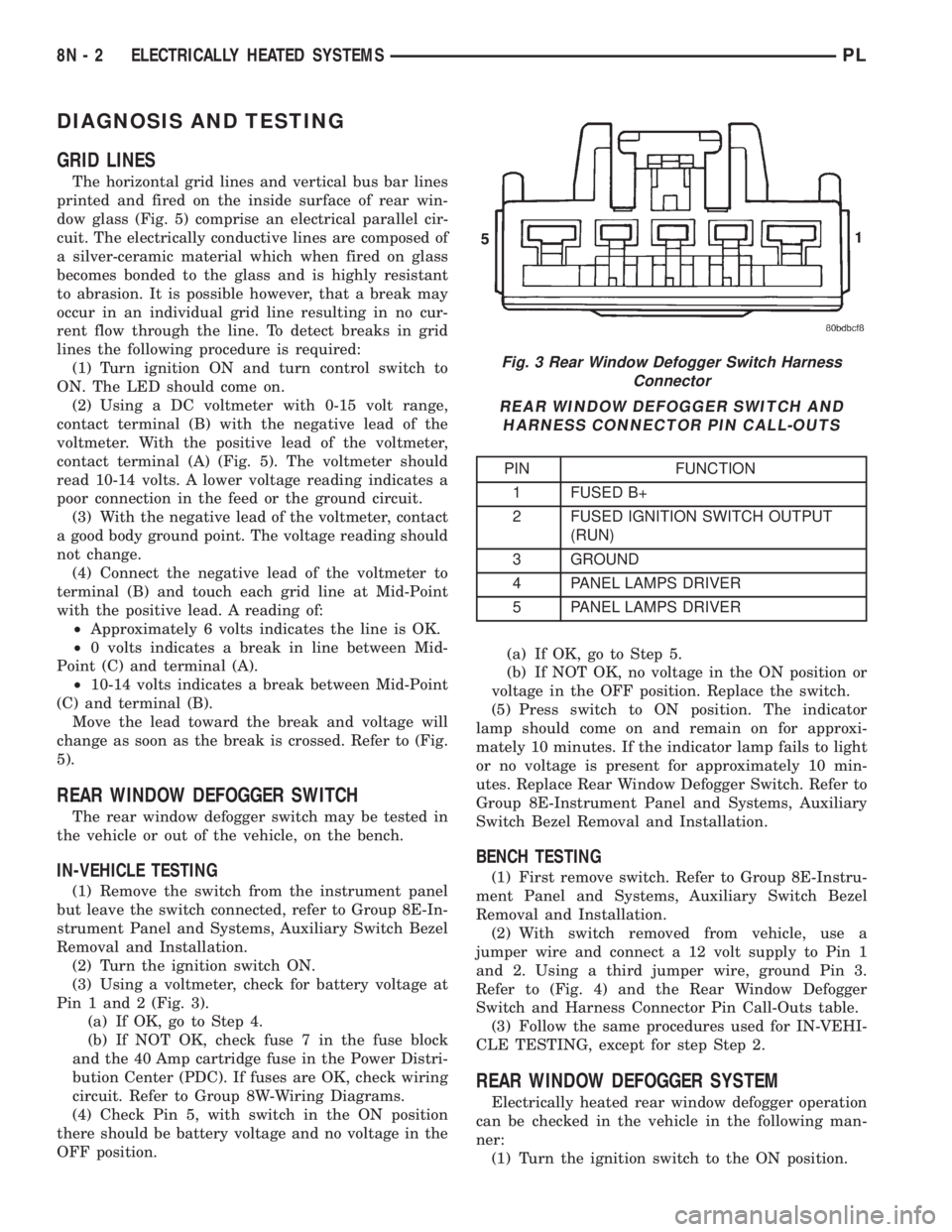
(3) Using a voltmeter, check for battery voltage at
Pin 1 and 2 (Fig. 3).
(a) If OK, go to Step 4.
(b) If NOT OK, check fuse 7 in the fuse block
and the 40 Amp cartridge fuse in the Power Distri-
bution Center (PDC). If fuses are OK, check wiring
circuit. Refer to Group 8W-Wiring Diagrams.
(4) Check Pin 5, with switch in the ON position
there should be battery voltage and no voltage in the
OFF position.(a) If OK, go to Step 5.
(b) If NOT OK, no voltage in the ON position or
voltage in the OFF position. Replace the switch.
(5) Press switch to ON position. The indicator
lamp should come on and remain on for approxi-
mately 10 minutes. If the indicator lamp fails to light
or no voltage is present for approximately 10 min-
utes. Replace Rear Window Defogger Switch. Refer to
Group 8E-Instrument Panel and Systems, Auxiliary
Switch Bezel Removal and Installation.
BENCH TESTING
(1) First remove switch. Refer to Group 8E-Instru-
ment Panel and Systems, Auxiliary Switch Bezel
Removal and Installation.
(2) With switch removed from vehicle, use a
jumper wire and connect a 12 volt supply to Pin 1
and 2. Using a third jumper wire, ground Pin 3.
Refer to (Fig. 4) and the Rear Window Defogger
Switch and Harness Connector Pin Call-Outs table.
(3) Follow the same procedures used for IN-VEHI-
CLE TESTING, except for step Step 2.
REAR WINDOW DEFOGGER SYSTEM
Electrically heated rear window defogger operation
can be checked in the vehicle in the following man-
ner:
(1) Turn the ignition switch to the ON position.
Fig. 3 Rear Window Defogger Switch Harness
Connector
REAR WINDOW DEFOGGER SWITCH AND
HARNESS CONNECTOR PIN CALL-OUTS
PIN FUNCTION
1 FUSED B+
2 FUSED IGNITION SWITCH OUTPUT
(RUN)
3 GROUND
4 PANEL LAMPS DRIVER
5 PANEL LAMPS DRIVER
8N - 2 ELECTRICALLY HEATED SYSTEMSPL