2000 DODGE NEON fuel filter location
[x] Cancel search: fuel filter locationPage 3 of 1285

LUBRICANTS AND GREASES
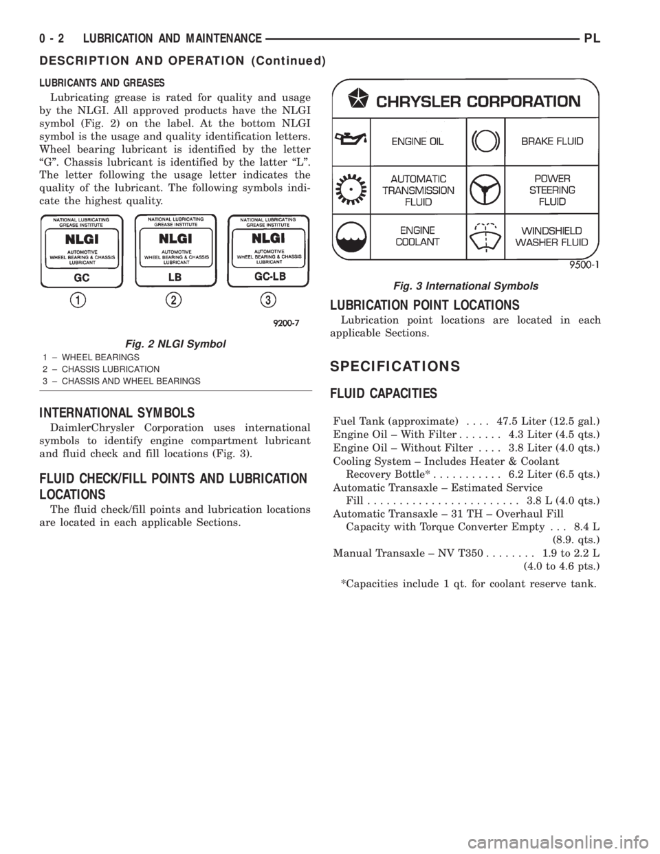
Lubricating grease is rated for quality and usage
by the NLGI. All approved products have the NLGI
symbol (Fig. 2) on the label. At the bottom NLGI
symbol is the usage and quality identification letters.
Wheel bearing lubricant is identified by the letter
ªGº. Chassis lubricant is identified by the latter ªLº.
The letter following the usage letter indicates the
quality of the lubricant. The following symbols indi-
cate the highest quality.
INTERNATIONAL SYMBOLS
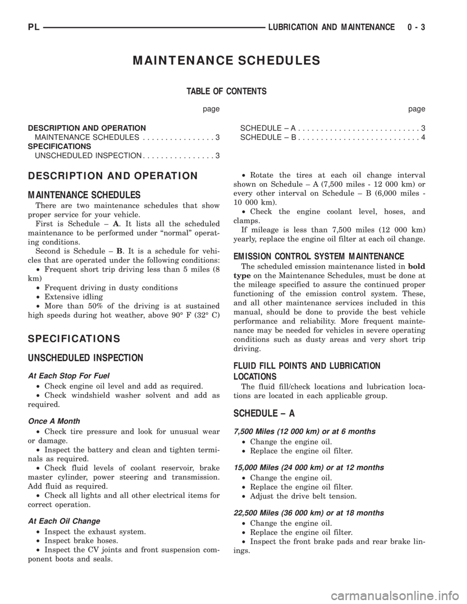
DaimlerChrysler Corporation uses international
symbols to identify engine compartment lubricant
and fluid check and fill locations (Fig. 3).
FLUID CHECK/FILL POINTS AND LUBRICATION
LOCATIONS
The fluid check/fill points and lubrication locations
are located in each applicable Sections.
LUBRICATION POINT LOCATIONS
Lubrication point locations are located in each
applicable Sections.
SPECIFICATIONS
FLUID CAPACITIES
Fuel Tank (approximate)....47.5 Liter (12.5 gal.)
Engine Oil ± With Filter....... 4.3Liter (4.5 qts.)
Engine Oil ± Without Filter.... 3.8Liter (4.0 qts.)
Cooling System ± Includes Heater & Coolant
Recovery Bottle*........... 6.2Liter (6.5 qts.)
Automatic Transaxle ± Estimated Service
Fill........................ 3.8L(4.0 qts.)
Automatic Transaxle ± 31 TH ± Overhaul Fill
Capacity with Torque Converter Empty . . . 8.4 L
(8.9. qts.)
Manual Transaxle ± NV T350........ 1.9to2.2L
(4.0 to 4.6 pts.)
*Capacities include 1 qt. for coolant reserve tank.
Fig. 2 NLGI Symbol
1 ± WHEEL BEARINGS
2 ± CHASSIS LUBRICATION
3 ± CHASSIS AND WHEEL BEARINGS
Fig. 3 International Symbols
0 - 2 LUBRICATION AND MAINTENANCEPL
DESCRIPTION AND OPERATION (Continued)
Page 4 of 1285

MAINTENANCE SCHEDULES
TABLE OF CONTENTS
page page
DESCRIPTION AND OPERATION
MAINTENANCE SCHEDULES................3
SPECIFICATIONS
UNSCHEDULED INSPECTION................3SCHEDULE ± A...........................3
SCHEDULE ± B...........................4
DESCRIPTION AND OPERATION
MAINTENANCE SCHEDULES
There are two maintenance schedules that show
proper service for your vehicle.
First is Schedule ±A. It lists all the scheduled
maintenance to be performed under ªnormalº operat-
ing conditions.
Second is Schedule ±B. It is a schedule for vehi-
cles that are operated under the following conditions:
²Frequent short trip driving less than 5 miles (8
km)
²Frequent driving in dusty conditions
²Extensive idling
²More than 50% of the driving is at sustained
high speeds during hot weather, above 90É F (32É C)
SPECIFICATIONS
UNSCHEDULED INSPECTION
At Each Stop For Fuel
²Check engine oil level and add as required.
²Check windshield washer solvent and add as
required.
Once A Month
²Check tire pressure and look for unusual wear
or damage.
²Inspect the battery and clean and tighten termi-
nals as required.
²Check fluid levels of coolant reservoir, brake
master cylinder, power steering and transmission.
Add fluid as required.
²Check all lights and all other electrical items for
correct operation.
At Each Oil Change
²Inspect the exhaust system.
²Inspect brake hoses.
²Inspect the CV joints and front suspension com-
ponent boots and seals.²Rotate the tires at each oil change interval
shown on Schedule ± A (7,500 miles - 12 000 km) or
every other interval on Schedule ± B (6,000 miles -
10 000 km).
²Check the engine coolant level, hoses, and
clamps.
If mileage is less than 7,500 miles (12 000 km)
yearly, replace the engine oil filter at each oil change.
EMISSION CONTROL SYSTEM MAINTENANCE
The scheduled emission maintenance listed inbold
typeon the Maintenance Schedules, must be done at
the mileage specified to assure the continued proper
functioning of the emission control system. These,
and all other maintenance services included in this
manual, should be done to provide the best vehicle
performance and reliability. More frequent mainte-
nance may be needed for vehicles in severe operating
conditions such as dusty areas and very short trip
driving.
FLUID FILL POINTS AND LUBRICATION
LOCATIONS
The fluid fill/check locations and lubrication loca-
tions are located in each applicable group.
SCHEDULE ± A
7,500 Miles (12 000 km) or at 6 months
²Change the engine oil.
²Replace the engine oil filter.
15,000 Miles (24 000 km) or at 12 months
²Change the engine oil.
²Replace the engine oil filter.
²Adjust the drive belt tension.
22,500 Miles (36 000 km) or at 18 months
²Change the engine oil.
²Replace the engine oil filter.
²Inspect the front brake pads and rear brake lin-
ings.
PLLUBRICATION AND MAINTENANCE 0 - 3
Page 729 of 1285

any fluid that may possibly be in the cylinder under
pressure.
(4) With all spark plugs removed, rotate engine
crankshaft using a breaker bar and socket.
(5) Identify the fluid in the cylinder(s) (i.e., cool-
ant, fuel, oil or other).
(6) Make sure all fluid has been removed from the
cylinders. Inspect engine for damage (i.e., connecting
rods, pistons, valves, etc.).
(7) Repair engine or components as necessary to
prevent this problem from re-occurring.
CAUTION: Squirt approximately one teaspoon of oil
into the cylinders, rotate engine to lubricate the cyl-
inder walls to prevent damage on restart.
(8) Install new spark plugs.
(9) Drain engine oil and remove oil filter.
(10) Fill engine with specified amount of approved
oil and install new oil filter.
(11) Connect negative battery cable.
(12) Start engine and check for any leaks.
CHECKING ENGINE OIL LEVEL
The best time to check engine oil level is after it
has sat overnight, or if the engine has been running,allow the engine to be shut off for at least 5 minutes
before checking oil level.
Checking the oil while the vehicle is on level
ground will improve the accuracy of the oil level
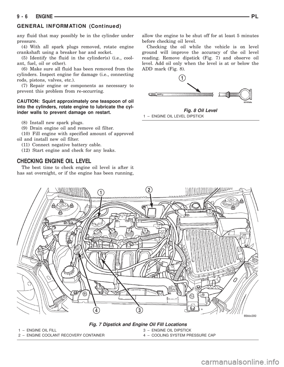
reading. Remove dipstick (Fig. 7) and observe oil
level. Add oil only when the level is at or below the
ADD mark (Fig. 8).
Fig. 7 Dipstick and Engine Oil Fill Locations
1 ± ENGINE OIL FILL
2 ± ENGINE COOLANT RECOVERY CONTAINER3 ± ENGINE OIL DIPSTICK
4 ± COOLING SYSTEM PRESSURE CAP
Fig. 8 Oil Level
1 ± ENGINE OIL LEVEL DIPSTICK
9 - 6 ENGINEPL
GENERAL INFORMATION (Continued)
Page 826 of 1285

OPERATION
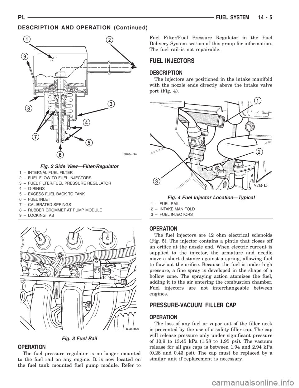
The fuel pressure regulator is no longer mounted
to the fuel rail on any engine. It is now located on
the fuel tank mounted fuel pump module. Refer toFuel Filter/Fuel Pressure Regulator in the Fuel
Delivery System section of this group for information.
The fuel rail is not repairable.
FUEL INJECTORS
DESCRIPTION
The injectors are positioned in the intake manifold
with the nozzle ends directly above the intake valve
port (Fig. 4).
OPERATION
The fuel injectors are 12 ohm electrical solenoids
(Fig. 5). The injector contains a pintle that closes off
an orifice at the nozzle end. When electric current is
supplied to the injector, the armature and needle
move a short distance against a spring, allowing fuel
to flow out the orifice. Because the fuel is under high
pressure, a fine spray is developed in the shape of a
hollow cone. The spraying action atomizes the fuel,
adding it to the air entering the combustion chamber.
Fuel injectors are not interchangeable between
engines.
PRESSURE-VACUUM FILLER CAP
OPERATION
The loss of any fuel or vapor out of the filler neck
is prevented by the use of a safety filler cap. The cap
will release pressure only under significant pressure
of 10.9 to 13.45 kPa (1.58 to 1.95 psi). The vacuum
release for all gas caps is between 1.94 and 2.94 kPa
(0.28 and 0.43 psi). The cap must be replaced by a
similar unit if replacement is necessary.
Fig. 2 Side ViewÐFilter/Regulator
1 ± INTERNAL FUEL FILTER
2 ± FUEL FLOW TO FUEL INJECTORS
3 ± FUEL FILTER/FUEL PRESSURE REGULATOR
4 ± O-RINGS
5 ± EXCESS FUEL BACK TO TANK
6 ± FUEL INLET
7 ± CALIBRATED SPRINGS
8 ± RUBBER GROMMET AT PUMP MODULE
9 ± LOCKING TAB
Fig. 3 Fuel Rail
Fig. 4 Fuel Injector LocationÐTypical
1 ± FUEL RAIL
2 ± INTAKE MANIFOLD
3 ± FUEL INJECTORS
PLFUEL SYSTEM 14 - 5
DESCRIPTION AND OPERATION (Continued)
Page 833 of 1285

REMOVAL AND INSTALLATION
AUTOMATIC SHUTDOWN RELAY
The relay is located in the Power Distribution Cen-
ter (PDC) (Fig. 12). The PDC is located next to the
battery in the engine compartment. For the location
of the relay within the PDC, refer to the PDC cover
for location. Check electrical terminals for corrosion
and repair as necessary.
FUEL PUMP RELAY
The fuel pump relay is located in the PDC. The
inside top of the PDC cover has a label showing relay
and fuse location.
FUEL PUMP MODULE
REMOVAL
WARNING: RELEASE FUEL SYSTEM PRESSURE
BEFORE SERVICING FUEL SYSTEM COMPONENTS.
SERVICE VEHICLES IN WELL VENTILATED AREAS
AND AVOID IGNITION SOURCES. NEVER SMOKE
WHILE SERVICING THE VEHICLE.
(1) Drain the fuel. Refer to Draining Fuel Tank in
the Fuel Tank section of this group.
WARNING: THE FUEL RESERVOIR OF THE FUEL
PUMP MODULE DOES NOT EMPTY OUT WHEN THE
TANK IS DRAINED. THE FUEL IN THE RESERVOIR
WILL SPILL OUT WHEN THE MODULE IS
REMOVED.
(2) Remove fuel tank, refer to the Fuel Tank
removal/installation section.
(3) Lower tank.(4) Use Special Tool 6856 to remove fuel pump
module locknut (Fig. 15).
(5) Remove fuel pump and O-ring seal from tank.
Discard old seal.
INSTALLATION
(1) Wipe seal area of tank clean and place a new
seal in position in the tank opening.
(2) Position fuel pump in the tank. Make sure the
alignment tab on the underside of the fuel pump
module flange sits in the notch on the fuel tank (Fig.
14).
(3) Position the locknut over the fuel pump mod-
ule.
Fig. 12 Power Distribution Center (PDC)
Fig. 13 Fuel Pump Module Removal
1 ± FUEL FILTER/PRESSURE REGULATOR
2 ± FUEL LINE
3 ± LOCKNUT
Fig. 14 Alignment Tab
14 - 12 FUEL SYSTEMPL