2000 DODGE NEON height adjustment
[x] Cancel search: height adjustmentPage 12 of 1285
SUSPENSION
TABLE OF CONTENTS
page page
WHEEL ALIGNMENT........................ 1
FRONT SUSPENSION....................... 9REAR SUSPENSION....................... 35
WHEEL ALIGNMENT
TABLE OF CONTENTS
page page
DESCRIPTION AND OPERATION
WHEEL ALIGNMENT.......................1
DIAGNOSIS AND TESTING
SUSPENSION AND STEERING DIAGNOSIS.....3
SERVICE PROCEDURES
CURB HEIGHT MEASUREMENT..............5WHEEL ALIGNMENT.......................5
SPECIFICATIONS
WHEEL ALIGNMENT SPECIFICATIONS.........8
DESCRIPTION AND OPERATION
WHEEL ALIGNMENT
Proper vehicle wheel alignment is the proper
adjustment of all interrelated front and rear suspen-
sion angles. These angles are what affects the han-
dling and steering of the vehicle when it is in motion.
The method of checking a vehicle's front and rear
wheel alignment will vary depending on the type and
manufacturer of the equipment being used. Instruc-
tions furnished by the manufacturer of the equip-
ment being used should always be followed to ensure
accuracy of the alignment, except when alignment
specifications recommended by this corporation differ.
Typical wheel alignment angles and measurements
are camber, caster, toe, and thrust angle.
²Camber is the number of degrees the top of the
tire and wheel are tilted either inward or outward
(Fig. 1). Camber is a tire wearing angle. Excessive
negative camber will cause tread wear at the inside
of the tire, while excessive positive camber will cause
outside tire wear.²Caster is the number of degrees of forward or
rearward tilt of the steering knuckle. Forward tilt
provides a negative caster angle, while rearward tilt
provides a positive caster angle. Caster is not adjust-
able on this vehicle.
²Cross Camber is the difference between left and
right camber. The right side camber is to be sub-
tracted from the left, resulting in the cross camber
reading. For example, if the left camber is +0.3É and
the right camber is 0.0É, the cross camber would be
+0.3É.
²Toe is measured in degrees or inches and is the
difference in width between the centered leading and
trailing edges of the tires on the same axle (Fig. 1).
Toe-in means that the front width is more narrow
than the rear. Toe-out means that the front width is
wider than the rear.
²Thrust Angle is defined as the average of the toe
settings on each rear wheel. If this measurement is
out of specification, readjust the rear wheel toe so
that each wheel has 1/2 of the total toe measure-
ment. When readjusting, do not exceed the total toe
specification.
PLSUSPENSION 2 - 1
Page 16 of 1285
SERVICE PROCEDURES
CURB HEIGHT MEASUREMENT
The wheel alignment is to be checked and all align-
ment adjustments made with the vehicle at its
required curb height specification.
Vehicle height is to be checked with the vehicle on
a flat, level surface, preferably a vehicle alignment
rack. The tires are to be inflated to the recommended
pressure. All tires are to be the same size as stan-
dard equipment. Vehicle height is checked with the
fuel tank full of fuel, and no passenger or luggage
compartment load.
Vehicle height is not adjustable. If the measure-
ment is not within specifications, inspect the vehicle
for bent or weak suspension components. Compare
the parts tag on the suspect coil spring(s) to the
parts book and the vehicle sales code, checking for a
match. Once removed from the vehicle, compare thecoil spring height to a correct new or known good coil
spring. The heights should vary if the suspect spring
is weak.
NOTE: Prior to reading the curb height measure-
ment, the front an rear of the vehicle should be
jounced. Induce jounce by grasping the center of
the rear, then front bumper (or fascia) and jouncing
the vehicle an equal number of times. Release the
bumper at the bottom of the jounce cycle.
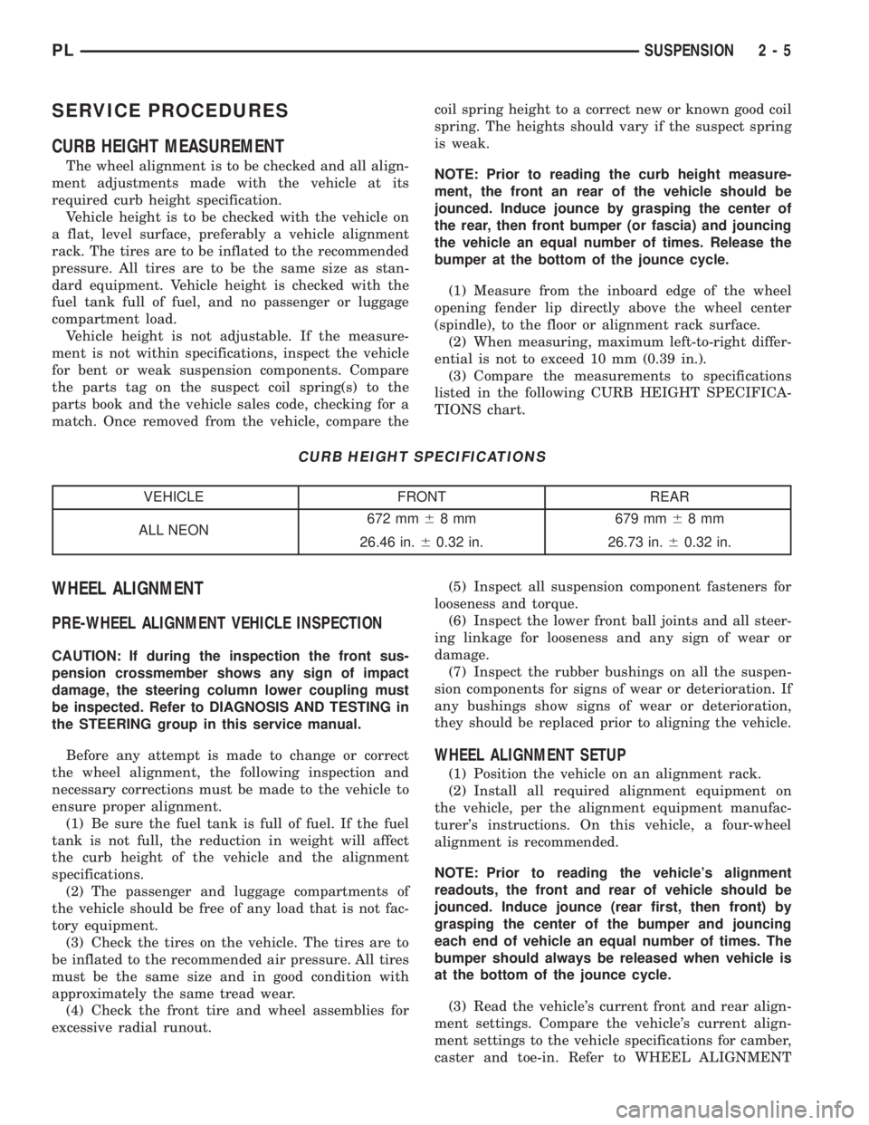
(1) Measure from the inboard edge of the wheel
opening fender lip directly above the wheel center
(spindle), to the floor or alignment rack surface.
(2) When measuring, maximum left-to-right differ-
ential is not to exceed 10 mm (0.39 in.).
(3) Compare the measurements to specifications
listed in the following CURB HEIGHT SPECIFICA-
TIONS chart.
CURB HEIGHT SPECIFICATIONS
VEHICLE FRONT REAR
ALL NEON672 mm68 mm 679 mm68mm
26.46 in.60.32 in. 26.73 in.60.32 in.
WHEEL ALIGNMENT
PRE-WHEEL ALIGNMENT VEHICLE INSPECTION
CAUTION: If during the inspection the front sus-
pension crossmember shows any sign of impact
damage, the steering column lower coupling must
be inspected. Refer to DIAGNOSIS AND TESTING in
the STEERING group in this service manual.
Before any attempt is made to change or correct
the wheel alignment, the following inspection and
necessary corrections must be made to the vehicle to
ensure proper alignment.
(1) Be sure the fuel tank is full of fuel. If the fuel
tank is not full, the reduction in weight will affect
the curb height of the vehicle and the alignment
specifications.
(2) The passenger and luggage compartments of
the vehicle should be free of any load that is not fac-
tory equipment.
(3) Check the tires on the vehicle. The tires are to
be inflated to the recommended air pressure. All tires
must be the same size and in good condition with
approximately the same tread wear.
(4) Check the front tire and wheel assemblies for
excessive radial runout.(5) Inspect all suspension component fasteners for
looseness and torque.
(6) Inspect the lower front ball joints and all steer-
ing linkage for looseness and any sign of wear or
damage.
(7) Inspect the rubber bushings on all the suspen-
sion components for signs of wear or deterioration. If
any bushings show signs of wear or deterioration,
they should be replaced prior to aligning the vehicle.
WHEEL ALIGNMENT SETUP
(1) Position the vehicle on an alignment rack.
(2) Install all required alignment equipment on
the vehicle, per the alignment equipment manufac-
turer's instructions. On this vehicle, a four-wheel
alignment is recommended.
NOTE: Prior to reading the vehicle's alignment
readouts, the front and rear of vehicle should be
jounced. Induce jounce (rear first, then front) by
grasping the center of the bumper and jouncing
each end of vehicle an equal number of times. The
bumper should always be released when vehicle is
at the bottom of the jounce cycle.
(3) Read the vehicle's current front and rear align-
ment settings. Compare the vehicle's current align-
ment settings to the vehicle specifications for camber,
caster and toe-in. Refer to WHEEL ALIGNMENT
PLSUSPENSION 2 - 5
Page 56 of 1285
LATERAL ARMS
NOTE: Before proceeding with this procedure,
review SERVICE WARNINGS AND CAUTIONS at the
beginning of REMOVAL AND INSTALLATION in this
section.
Use the following procedure for removal and instal-
lation of one or both lateral arms on one side of the
vehicle's rear suspension.
REMOVAL
(1) Raise the vehicle. Refer to HOISTING in the
LUBRICATION AND MAINTENANCE group for the
proper lifting procedure.
(2) Remove the rear tire and wheel assembly.
(3) Remove the nut, bolt and washers attaching
both lateral arms to the knuckle (Fig. 1).
(4) Remove nut, washer, bolt and wheel alignment
cam attaching the lateral arms to the rear crossmem-
ber (Fig. 1).
(5) Remove the lateral arms from vehicle.
INSTALLATION
NOTE: Both lateral arms when being installed,
must be specifically positioned and orientated on
the vehicle. The lateral arm that has the same size
bushing sleeves on both ends must be mounted on
the forward side of the crossmember and knuckle
with the trimmed outer edge facing rearward. This
front arm is also marked with the word ªFOR-
WARDº. The side of the arm displaying this must
face forward.
The lateral arm with two different size bushing
sleeves must be mounted on the rearward side of
the crossmember and knuckle. Position the smaller
bushing sleeve end at the knuckle and the larger
bushing sleeve end at the rear crossmember (the
larger bushing sleeve is necessary to accommodate
the rear wheel alignment adjustment cam). If the
rear arm is to be mounted on the right side, the
trimmed outer edge must face rearward. If the rear
arm is to be mounted on the left side, the trimmed
outer edge must face forward.
(1) Following the note above, place the forward lat-
eral arm against the leading end of the knuckle, and
then install the short lateral arm mounting bolt with
a washer through the lateral arm and knuckle and
out the trailing end of the knuckle (Fig. 1).
(2) Following the note above, install the small
bushing sleeved end of the rear lateral arm onto the
end of the bolt just installed through the knuckle
(Fig. 1). Install a washer and nut onto the end of the
mounting bolt, but do not completely tighten the bolt
at this time.(3) Install a wheel alignment adjustment cam on
the long arm mounting bolt.
(4) Hold the rear lateral arm up against the cross-
member and install the long mounting bolt with the
adjustment cam through the lateral arm bushing and
rear crossmember (Fig. 1). The bolt must be installed
with the notch in the adjustment cam pointing
straight up.
(5) Position the forward lateral arm against the
rear crossmember hole. Pass the long mounting bolt
through the lateral arm bushing sleeve.
(6) Install a washer and nut onto the end of lateral
arm mounting bolt at the rear crossmember, but do
not completely tighten the bolt at this time.
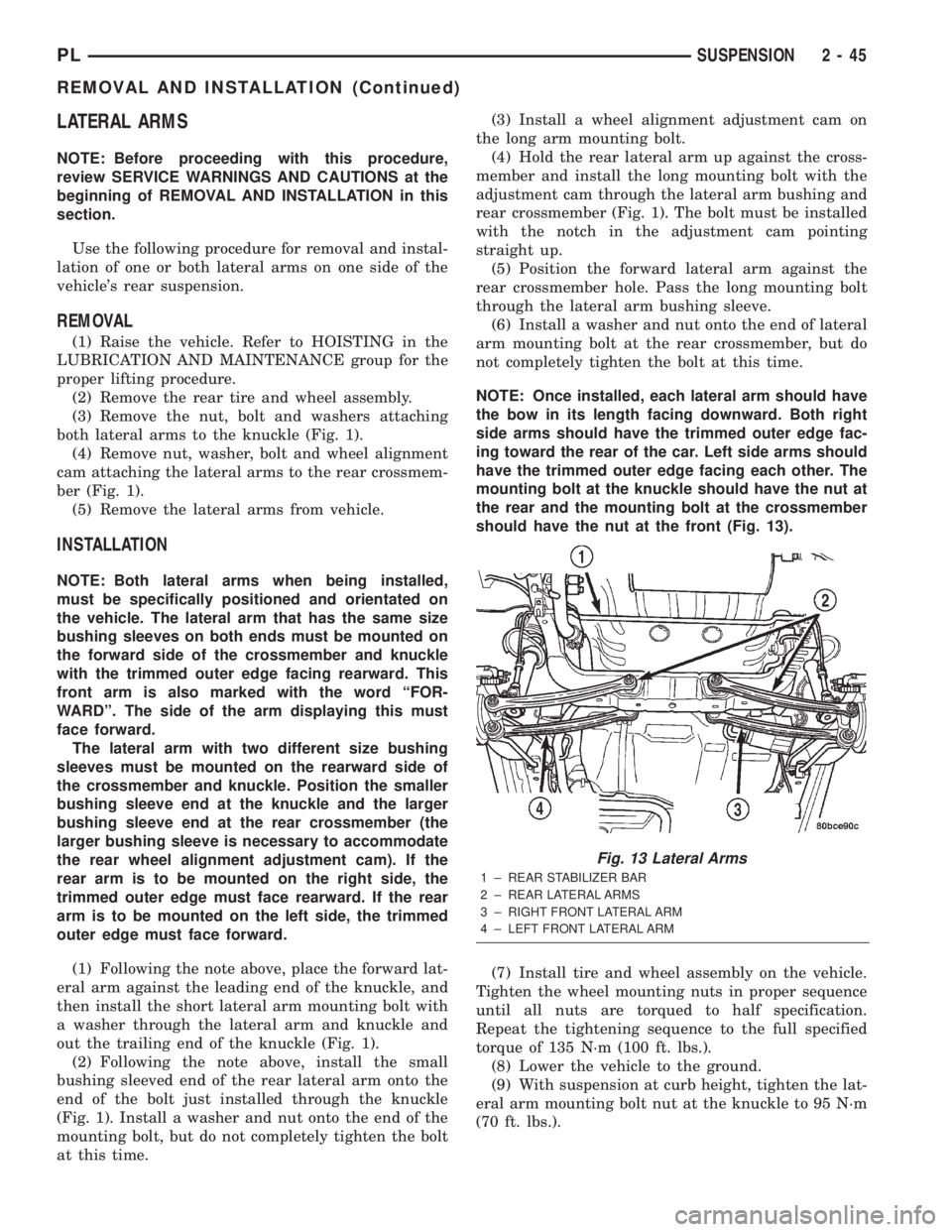
NOTE: Once installed, each lateral arm should have
the bow in its length facing downward. Both right
side arms should have the trimmed outer edge fac-
ing toward the rear of the car. Left side arms should
have the trimmed outer edge facing each other. The
mounting bolt at the knuckle should have the nut at
the rear and the mounting bolt at the crossmember
should have the nut at the front (Fig. 13).
(7) Install tire and wheel assembly on the vehicle.
Tighten the wheel mounting nuts in proper sequence
until all nuts are torqued to half specification.
Repeat the tightening sequence to the full specified
torque of 135 N´m (100 ft. lbs.).
(8) Lower the vehicle to the ground.
(9) With suspension at curb height, tighten the lat-
eral arm mounting bolt nut at the knuckle to 95 N´m
(70 ft. lbs.).
Fig. 13 Lateral Arms
1 ± REAR STABILIZER BAR
2 ± REAR LATERAL ARMS
3 ± RIGHT FRONT LATERAL ARM
4 ± LEFT FRONT LATERAL ARM
PLSUSPENSION 2 - 45
REMOVAL AND INSTALLATION (Continued)
Page 327 of 1285
HEADLAMP ALIGNMENT
TABLE OF CONTENTS
page page
DESCRIPTION AND OPERATION
HEADLAMP ALIGNMENT....................2
SERVICE PROCEDURES
HEADLAMP ALIGNMENT PREPARATION........2ADJUSTMENTS
HEADLAMP ADJUSTMENT USING
ALIGNMENT SCREEN....................2
DESCRIPTION AND OPERATION
HEADLAMP ALIGNMENT
Headlamps can be aligned using the screen method
provided in this section. This method will require the
vehicle to be parked on a flat, level surface with a
minimum of 15 meters of working room in front of a
flat, level perpendicular wall or aiming.
Each headlamp has a focal point circle molded on
the lens directly in front of each headlamp bulb.
These focal point circles are used to set up lines on a
wall, or aiming board for visually aiming the head-
lamps.
The driving (high) beam location does not require
adjustment. It will be correct when the passing (low)
beam headlamps are aimed correctly.
SERVICE PROCEDURES
HEADLAMP ALIGNMENT PREPARATION
(1) Verify headlamp dimmer switch and high beam
indicator operation.
(2) Inspect and correct damaged or defective com-
ponents that could interfere with proper headlamp
alignment.
(3) Verify that the headlamp leveling switch is in
the ª0º position.
(4) Verify proper tire inflation.
(5) Clean the headlamp lenses.
(6) Verify that the luggage area is not heavily
loaded.
(7) Fuel tank should be FULL. Add 2.94 kg (6.5
lbs.) of weight over the fuel tank for each estimated
gallon of missing fuel.
ADJUSTMENTS
HEADLAMP ADJUSTMENT USING ALIGNMENT
SCREEN
ALIGNMENT SCREEN PREPARATION
(1) Position the vehicle on a level surface 10
meters in front of a level, flat wall or aiming board.
(2) Tape a vertical line on the wall extending 1
meter up from the floor, making sure this line is even
with the centerline of the vehicle (Fig. 1).
(3) Measure the cross-car distance between the
two headlamp focal point circles (1174mm). Transfer
half of this distance (587mm) to the left of the vehicle
centerline and tape another vertical line up from the
floor 1 meter (Fig. 1). Repeat for the right side of the
centerline.
(4) Measure the distance from the floor to the focal
point circle on the headlamp lens (635mm, but may
vary due to variations in tire size and vehicle suspen-
sion height). Transfer this measurement to the wall
and tape a horizontal line extending approximately 1
meter beyond each vertical focal point line (Fig. 1).
(5) Use these lines for left and right adjustment
reference.
HEADLAMP ADJUSTMENT
Horizontal Adjustment
The horizontal position of the passing (low) beam
pattern is adjusted by turning the T-15 Torx screw.
Located through the slot in the upper-crossmember
between the two attaching straps of the headlamp.
Vertical Adjustment
The vertical position of the passing (low) beam pat-
tern is adjusted by turning the Phillips screw on top
of the headlamp leveling motor. Located between the
headlamp housing and the upper-crossmember, just
inboard of the fender.
Adjust the passing (low) beam headlamp pat-
terns to the locations shown in the chart pro-
vided (Fig. 1).
8L - 2 LAMPSPL
Page 784 of 1285
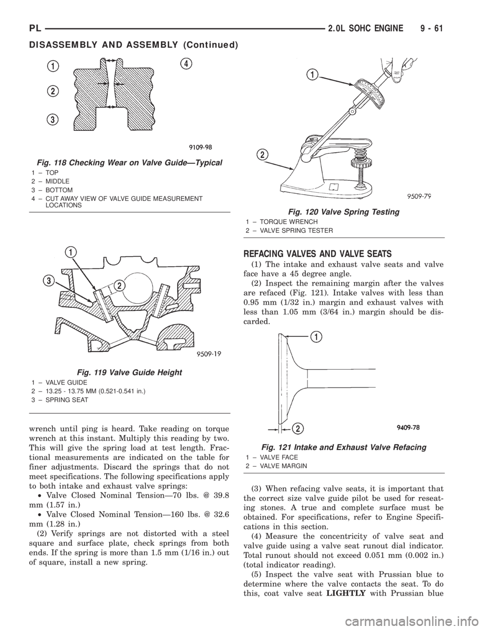
wrench until ping is heard. Take reading on torque
wrench at this instant. Multiply this reading by two.
This will give the spring load at test length. Frac-
tional measurements are indicated on the table for
finer adjustments. Discard the springs that do not
meet specifications. The following specifications apply
to both intake and exhaust valve springs:
²Valve Closed Nominal TensionÐ70 lbs. @ 39.8
mm (1.57 in.)
²Valve Closed Nominal TensionÐ160 lbs. @ 32.6
mm (1.28 in.)
(2) Verify springs are not distorted with a steel
square and surface plate, check springs from both
ends. If the spring is more than 1.5 mm (1/16 in.) out
of square, install a new spring.
REFACING VALVES AND VALVE SEATS
(1) The intake and exhaust valve seats and valve
face have a 45 degree angle.
(2) Inspect the remaining margin after the valves
are refaced (Fig. 121). Intake valves with less than
0.95 mm (1/32 in.) margin and exhaust valves with
less than 1.05 mm (3/64 in.) margin should be dis-
carded.
(3) When refacing valve seats, it is important that
the correct size valve guide pilot be used for reseat-
ing stones. A true and complete surface must be
obtained. For specifications, refer to Engine Specifi-
cations in this section.
(4) Measure the concentricity of valve seat and
valve guide using a valve seat runout dial indicator.
Total runout should not exceed 0.051 mm (0.002 in.)
(total indicator reading).
(5) Inspect the valve seat with Prussian blue to
determine where the valve contacts the seat. To do
this, coat valve seatLIGHTLYwith Prussian blue
Fig. 118 Checking Wear on Valve GuideÐTypical
1±TOP
2 ± MIDDLE
3 ± BOTTOM
4 ± CUT AWAY VIEW OF VALVE GUIDE MEASUREMENT
LOCATIONS
Fig. 119 Valve Guide Height
1 ± VALVE GUIDE
2 ± 13.25 - 13.75 MM (0.521-0.541 in.)
3 ± SPRING SEAT
Fig. 120 Valve Spring Testing
1 ± TORQUE WRENCH
2 ± VALVE SPRING TESTER
Fig. 121 Intake and Exhaust Valve Refacing
1 ± VALVE FACE
2 ± VALVE MARGIN
PL2.0L SOHC ENGINE 9 - 61
DISASSEMBLY AND ASSEMBLY (Continued)