2000 DODGE NEON battery replacement
[x] Cancel search: battery replacementPage 68 of 1285
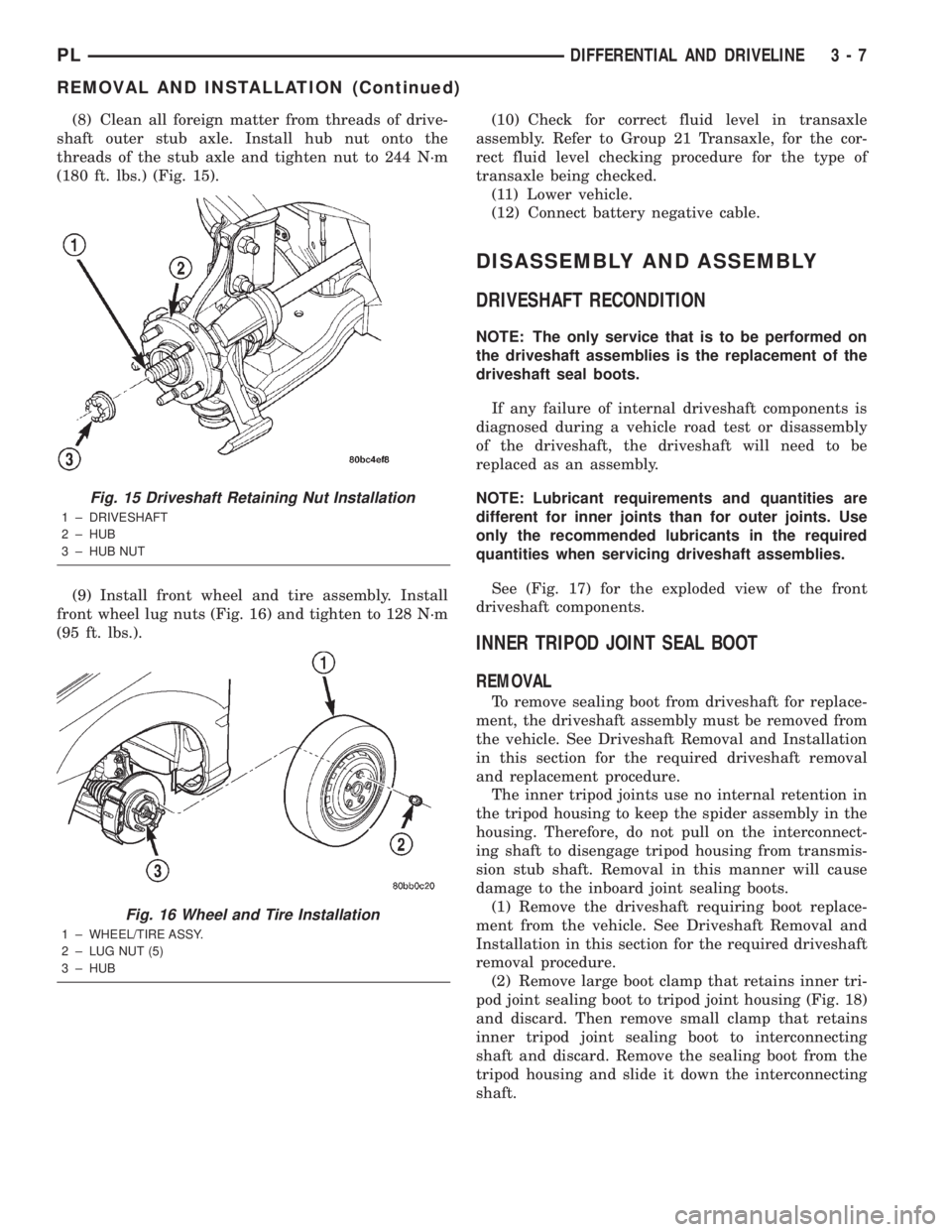
(8) Clean all foreign matter from threads of drive-
shaft outer stub axle. Install hub nut onto the
threads of the stub axle and tighten nut to 244 N´m
(180 ft. lbs.) (Fig. 15).
(9) Install front wheel and tire assembly. Install
front wheel lug nuts (Fig. 16) and tighten to 128 N´m
(95 ft. lbs.).(10) Check for correct fluid level in transaxle
assembly. Refer to Group 21 Transaxle, for the cor-
rect fluid level checking procedure for the type of
transaxle being checked.
(11) Lower vehicle.
(12) Connect battery negative cable.
DISASSEMBLY AND ASSEMBLY
DRIVESHAFT RECONDITION
NOTE: The only service that is to be performed on
the driveshaft assemblies is the replacement of the
driveshaft seal boots.
If any failure of internal driveshaft components is
diagnosed during a vehicle road test or disassembly
of the driveshaft, the driveshaft will need to be
replaced as an assembly.
NOTE: Lubricant requirements and quantities are
different for inner joints than for outer joints. Use
only the recommended lubricants in the required
quantities when servicing driveshaft assemblies.
See (Fig. 17) for the exploded view of the front
driveshaft components.
INNER TRIPOD JOINT SEAL BOOT
REMOVAL
To remove sealing boot from driveshaft for replace-
ment, the driveshaft assembly must be removed from
the vehicle. See Driveshaft Removal and Installation
in this section for the required driveshaft removal
and replacement procedure.
The inner tripod joints use no internal retention in
the tripod housing to keep the spider assembly in the
housing. Therefore, do not pull on the interconnect-
ing shaft to disengage tripod housing from transmis-
sion stub shaft. Removal in this manner will cause
damage to the inboard joint sealing boots.
(1) Remove the driveshaft requiring boot replace-
ment from the vehicle. See Driveshaft Removal and
Installation in this section for the required driveshaft
removal procedure.
(2) Remove large boot clamp that retains inner tri-
pod joint sealing boot to tripod joint housing (Fig. 18)
and discard. Then remove small clamp that retains
inner tripod joint sealing boot to interconnecting
shaft and discard. Remove the sealing boot from the
tripod housing and slide it down the interconnecting
shaft.
Fig. 15 Driveshaft Retaining Nut Installation
1 ± DRIVESHAFT
2 ± HUB
3 ± HUB NUT
Fig. 16 Wheel and Tire Installation
1 ± WHEEL/TIRE ASSY.
2 ± LUG NUT (5)
3 ± HUB
PLDIFFERENTIAL AND DRIVELINE 3 - 7
REMOVAL AND INSTALLATION (Continued)
Page 147 of 1285
CONTROLLER ANTILOCK BRAKE INPUTS
²wheel speed sensors (four)
²stop lamp switch
²ignition switch
²system relay voltage
²ground
²traction control lamp
²diagnostic communication (PCI)
CONTROLLER ANTILOCK BRAKE OUTPUTS
²amber ABS warning lamp actuation (through
MIC)
²red BRAKE warning lamp actuation (through
MIC)
²traction control lamp actuation (through MIC)
²diagnostic communication. (PCI)
HYDRAULIC CONTROL UNIT (HCU)
The hydraulic control unit (HCU) is mounted to
the CAB as part of the ICU (Fig. 2). The HCU con-
trols the flow of brake fluid to the brakes using a
series of valves and accumulators. A pump/motor is
mounted on the HCU to supply build pressure to the
brakes during an ABS stop.
VALVES AND SOLENOIDS
The valve block contains four inlet valves and four
outlet solenoid valves. The inlet valves are spring-
loaded in the open position and the outlet valves are
spring-loaded in the closed position during normal
braking. The fluid is allowed to flow from the master
cylinder to the wheel brakes.
During an ABS stop, these valves cycle to maintain
the proper slip ratio for each wheel. The inlet valve
closes preventing further pressure increase and the
outlet valve opens to provide a path from the wheel
brake to the HCU accumulators and pump/motor.
This releases (decays) pressure from the wheel brake,
thus releasing the wheel from excessive slippage.
Once the wheel is no longer slipping, the outlet valve
is closed and the inlet valve is opened to reapply
(build) pressure.
There are four other valves in the HCU. These four
remaining valves are used for traction control. Two
traction control (TC) valves, mounted in the HCU
valve block, are normally in the open position and
close only when the traction control is applied. There
are also two shuttle valves which control pressure
return to the master cylinder under ABS and traction
control conditions.
These TC valves are used to isolate the rear (non-
driving) wheels of the vehicle from the hydraulic
pressure that the HCU pump/motor is sending to the
front (driving) wheels when traction control is being
applied. The rear brakes need to be isolated from the
master cylinder when traction control is beingapplied so the rear wheels do not drag. For more
information on the TC and shuttle valves, see TRAC-
TION CONTROL SYSTEM in this section.
BRAKE FLUID ACCUMULATORS
There are two fluid accumulators in the HCU: one
for the primary hydraulic circuit, and one for the sec-
ondary hydraulic circuit. Each hydraulic circuit uses
a 3 cc accumulator.
The fluid accumulators temporarily store brake
fluid that is removed from the wheel brakes during
an ABS cycle. This stored fluid is used by the pump/
motor to provide build pressure for the brake hydrau-
lic system. When the antilock stop is complete, the
accumulators are drained by the pump/motor.
There are two noise dampening chambers in the
HCU on this vehicle equipped with traction control.
PUMP/MOTOR
There are two pump assemblies in the HCU: one
for the primary hydraulic circuit, and one for the sec-
ondary hydraulic circuit. Both pumps are driven by a
common electric motor (Fig. 2). This DC-type motor
is integral to the HCU and is controlled by the CAB.
The pump/motor provides the extra amount of
brake fluid needed during antilock braking. Brake
fluid is released to the accumulators when the outlet
valve is opened during an antilock stop. The pump
mechanism consists of two opposing pistons operated
by an eccentric camshaft. In operation, these pistons
are used to purge fluid from the accumulators back
into the master cylinder circuits. When the antilock
stop is complete, the pump/motor drains the accumu-
lators.
The pump motor is also used to build pressure
when the system goes into traction control mode. For
more information, refer to TRACTION CONTROL
SYSTEM in this section.
The CAB may turn on the pump/motor when an
antilock stop is detected. The pump/motor continues
to run during the antilock stop and is turned off after
the stop is complete. Under some conditions, the
pump/motor runs to drain the accumulators during
the next drive-off.
The pump/motor is not a serviceable item; if it
requires replacement, the HCU must be replaced.
ABS FUSES
The ABS fuse and the ABS pump/motor fuse are
located in the power distribution center (PDC). Refer
to the sticker on the inside of the PDC cover for the
location of these fuses. The PDC is located on the
driver's side of the engine compartment between the
back of the battery and the brake master cylinder.
The CAB fuse can be found in the fuse junction
block under the instrument panel.
5 - 68 BRAKESPL
DESCRIPTION AND OPERATION (Continued)
Page 155 of 1285
junction block. A label on the underside of the PDC
cover identifies the locations of the ABS fuses.
(2) Inspect the 25-way electrical connector at the
CAB for damaged, spread, or backed-out wiring ter-
minals. Verify that the 25-way connector is fully
inserted in the socket of the CAB. Be sure that wires
are not stretched tight or pulled out of the connector.
(3) Verify that all the wheel speed sensor connec-
tions are secure.
(4) Look for poor mating of connector halves or ter-
minals not fully seated in the connector body.
(5)
Check for improperly formed or damaged termi-
nals. All connector terminals in a suspect circuit should
be carefully reformed to increase contact tension.
(6) Look for poor terminal-to-wire connections.
This requires removing the terminal from the connec-
tor body to inspect it.
(7) Verify pin presence in the connector assembly
(8) Check for proper ground connections. Check all
ground connections for signs of corrosion, loose fas-
teners, or other potential defects. Refer to the wiring
diagrams for ground locations.
(9) Look for problems with the main power sources
of the vehicle. Inspect the battery, generator, ignition
circuits and other related relays and fuses.
If a visual check does not find the cause of the
problem, operate the car in an attempt to duplicate
the condition and record any trouble codes.
Most failures of the ABS disable the ABS function
for the entire ignition cycle even if the fault clears
before key-off. There are some failure conditions,
however, that allow ABS operation to resume during
the ignition cycle in which the trouble occurred even
if the trouble conditions are no longer present.
The following trouble conditions may result in
intermittent illumination of the amber ABS warning
lamp.
²Low system voltage. If Low System Voltage is
detected by the CAB, the CAB will turn on the ABS
Warning Lamp until normal system voltage is
achieved. Once normal voltage is seen at the CAB,
normal operation resumes.
²High system voltage. If high system voltage is
detected by the CAB, the CAB will turn on the
Amber ABS Warning Lamp until normal system volt-
age is achieved. Once normal voltage is again
detected by the CAB, normal ABS operation resumes.
Additional possible causes that may result in the
illumination of the amber ABS warning lamp are as
follows:
²Any condition that interrupts electrical current
to the CAB may cause the amber ABS warning lamp
to turn on intermittently.
²If PCI communication between the body control-
ler and the CAB is interrupted, the body controller
can turn on the amber ABS warning lamp.
TONE WHEEL
Tone wheels can cause erratic wheel speed sensor
signals. Inspect tone wheels for the following possible
causes:
²missing, chipped, or broken teeth
²contact with the wheel speed sensor
²wheel speed sensor to tone wheel alignment
²wheel speed sensor to tone wheel clearance
²excessive tone wheel runout
²tone wheel loose on its mounting surface
If a front tone wheel is found to need replacement,
the drive shaft must be replaced. No attempt should
be made to replace just the tone wheel. Refer to the
DIFFERENTIAL AND DRIVELINE group in this
service manual for removal and installation.
If a rear tone wheel is found to need replacement,
the rear hub and bearing must be replaced. No
attempt should be made to replace just the tone
wheel. Refer to the SUSPENSION group in this ser-
vice manual for removal and installation.
If wheel speed sensor to tone wheel contact is evi-
dent, determine the cause and correct it before
replacing the wheel speed sensor or tone wheel.
Check the gap between the speed sensor head and
the tone wheel to ensure it is within specifications.
Refer to SPECIFICATIONS in this section of the ser-
vice manual for the minimum and maximum wheel
speed sensor to tone wheel clearance.
Excessive wheel speed sensor runout can cause
erratic wheel speed sensor signals. Refer to SPECI-
FICATIONS in this section of the service manual for
the maximum allowed tone wheel runout. If tone
wheel runout is excessive, determine if it is caused
by a defect in the driveshaft assembly or hub and
bearing. Replace as necessary.
Tone wheels are pressed onto their mounting sur-
faces and should not rotate independently from the
mounting surface. Replacement of the front drive-
shaft or rear hub and bearing is necessary.
BRAKE FLUID CONTAMINATION
Indications of fluid contamination are swollen or
deteriorated rubber parts. Swelling indicates the
presence of petroleum in the brake fluid.
To test for contamination, put a small amount of
drained brake fluid in clear glass jar. If the fluid sep-
arates into layers, there is mineral oil or other fluid
contamination of the brake fluid.
If the brake fluid is contaminated, drain and thor-
oughly flush the brake system. Replace all the rubber
parts or components containing rubber coming into
contact with the brake fluid including: the master
cylinder; proportioning valves; caliper seals; wheel
cylinder seals; ABS hydraulic control unit; and all
hydraulic fluid hoses.
5 - 76 BRAKESPL
DIAGNOSIS AND TESTING (Continued)
Page 157 of 1285
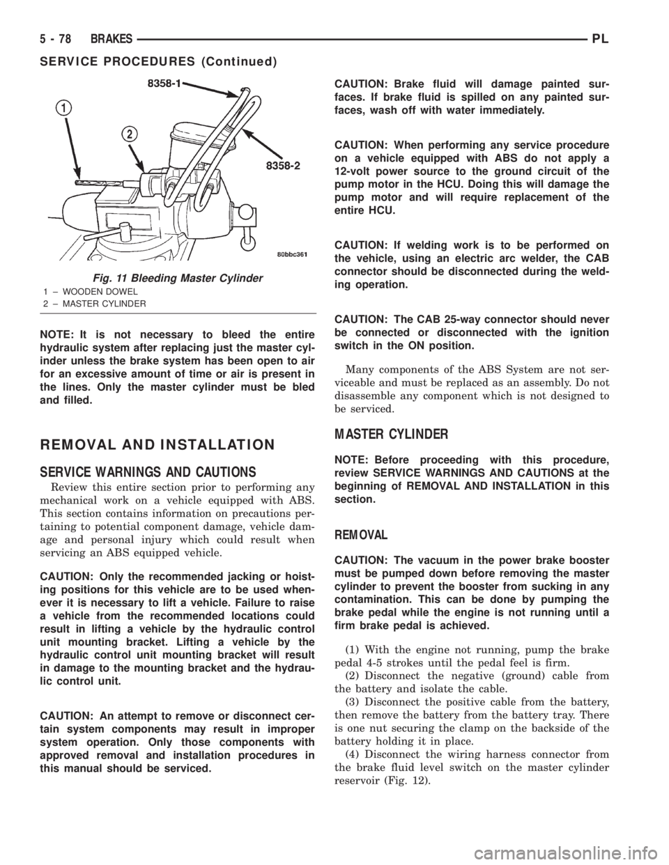
NOTE: It is not necessary to bleed the entire
hydraulic system after replacing just the master cyl-
inder unless the brake system has been open to air
for an excessive amount of time or air is present in
the lines. Only the master cylinder must be bled
and filled.
REMOVAL AND INSTALLATION
SERVICE WARNINGS AND CAUTIONS
Review this entire section prior to performing any
mechanical work on a vehicle equipped with ABS.
This section contains information on precautions per-
taining to potential component damage, vehicle dam-
age and personal injury which could result when
servicing an ABS equipped vehicle.
CAUTION: Only the recommended jacking or hoist-
ing positions for this vehicle are to be used when-
ever it is necessary to lift a vehicle. Failure to raise
a vehicle from the recommended locations could
result in lifting a vehicle by the hydraulic control
unit mounting bracket. Lifting a vehicle by the
hydraulic control unit mounting bracket will result
in damage to the mounting bracket and the hydrau-
lic control unit.
CAUTION: An attempt to remove or disconnect cer-
tain system components may result in improper
system operation. Only those components with
approved removal and installation procedures in
this manual should be serviced.CAUTION: Brake fluid will damage painted sur-
faces. If brake fluid is spilled on any painted sur-
faces, wash off with water immediately.
CAUTION: When performing any service procedure
on a vehicle equipped with ABS do not apply a
12-volt power source to the ground circuit of the
pump motor in the HCU. Doing this will damage the
pump motor and will require replacement of the
entire HCU.
CAUTION: If welding work is to be performed on
the vehicle, using an electric arc welder, the CAB
connector should be disconnected during the weld-
ing operation.
CAUTION: The CAB 25-way connector should never
be connected or disconnected with the ignition
switch in the ON position.
Many components of the ABS System are not ser-
viceable and must be replaced as an assembly. Do not
disassemble any component which is not designed to
be serviced.
MASTER CYLINDER
NOTE: Before proceeding with this procedure,
review SERVICE WARNINGS AND CAUTIONS at the
beginning of REMOVAL AND INSTALLATION in this
section.
REMOVAL
CAUTION: The vacuum in the power brake booster
must be pumped down before removing the master
cylinder to prevent the booster from sucking in any
contamination. This can be done by pumping the
brake pedal while the engine is not running until a
firm brake pedal is achieved.
(1) With the engine not running, pump the brake
pedal 4-5 strokes until the pedal feel is firm.
(2) Disconnect the negative (ground) cable from
the battery and isolate the cable.
(3) Disconnect the positive cable from the battery,
then remove the battery from the battery tray. There
is one nut securing the clamp on the backside of the
battery holding it in place.
(4) Disconnect the wiring harness connector from
the brake fluid level switch on the master cylinder
reservoir (Fig. 12).
Fig. 11 Bleeding Master Cylinder
1 ± WOODEN DOWEL
2 ± MASTER CYLINDER
5 - 78 BRAKESPL
SERVICE PROCEDURES (Continued)
Page 233 of 1285
Module (PCM). The EVR is not serviced separately. If
replacement is necessary, the PCM must be replaced.
OPERATION
The amount of DC current produced by the gener-
ator is controlled by EVR circuitry contained within
the PCM. This circuitry is connected in series with
the generators second rotor field terminal and its
ground.
Voltage is regulated by cycling the ground path to
control the strength of the rotor magnetic field. The
EVR circuitry monitors system line voltage (B+) and
battery temperature (refer to Battery Temperature
Sensor for more information). It then determines a
target charging voltage. If sensed battery voltage is
0.5 volts or lower than the target voltage, the PCM
grounds the field winding until sensed battery volage
is 0.5 volts above target voltage. A circuit in the PCM
cycles the ground side of the generator field up to
100 times per second (100Hz), but has the capability
to ground the field control wire 100% of the time (full
field) to achieve the target voltage. If the charging
rate cannot be monitored (limp-in), a duty cycle of
25% is used by the PCM in order to have some gen-
erator output. Also refer to Charging System Opera-
tion for additional information.
REMOVAL AND INSTALLATION
GENERATOR
REMOVAL
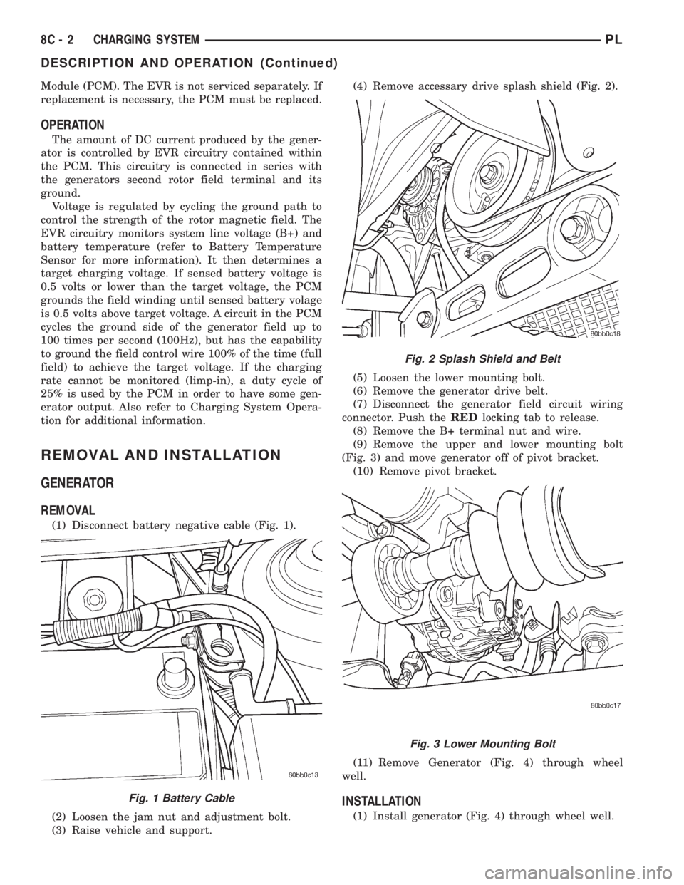
(1) Disconnect battery negative cable (Fig. 1).
(2) Loosen the jam nut and adjustment bolt.
(3) Raise vehicle and support.(4) Remove accessary drive splash shield (Fig. 2).
(5) Loosen the lower mounting bolt.
(6) Remove the generator drive belt.
(7) Disconnect the generator field circuit wiring
connector. Push theREDlocking tab to release.
(8) Remove the B+ terminal nut and wire.
(9) Remove the upper and lower mounting bolt
(Fig. 3) and move generator off of pivot bracket.
(10) Remove pivot bracket.
(11) Remove Generator (Fig. 4) through wheel
well.
INSTALLATION
(1) Install generator (Fig. 4) through wheel well.
Fig. 1 Battery Cable
Fig. 2 Splash Shield and Belt
Fig. 3 Lower Mounting Bolt
8C - 2 CHARGING SYSTEMPL
DESCRIPTION AND OPERATION (Continued)
Page 299 of 1285
DIAGNOSIS AND TESTING
WINDSHIELD WIPER CONDITIONS
WARNING: ON VEHICLES EQUIPPED WITH AIR-
BAGS, REFER TO GROUP 8M, PASSIVE
RESTRAINT SYSTEMS FOR STEERING WHEEL
REMOVAL AND INSTALLATION.
The following is a list of general wiper motor sys-
tem problems, the tests that are to be performed to
locate the faulty part, and the corrective action to be
taken.
Whatever the problem, disconnect motor wire har-
ness and clean the terminals, then connect motor
wire harness and test.
Refer to Group 8W Wiring Diagrams for circuit
information and connector call-outs.
MOTOR WILL NOT OPERATE IN SOME OR ALL
SWITCH POSITIONS
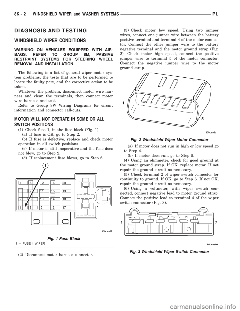
(1) Check fuse 1, in the fuse block (Fig. 1).
(a) If fuse is OK, go to Step 2.
(b) If fuse is defective, replace and check motor
operation in all switch positions.
(c) If motor is still inoperative and the fuse does
not blow, go to Step 2.
(d) If replacement fuse blows, go to Step 6.
(2) Disconnect motor harness connector.(3) Check motor low speed. Using two jumper
wires, connect one jumper wire between the battery
positive terminal and terminal 4 of the motor connec-
tor. Connect the other jumper wire to the battery
negative terminal and the motor ground strap (Fig.
2). Check motor high speed, connect the positive
jumper wire to terminal 5 of the motor connector.
Connect the negative jumper wire to the motor
ground strap.
(a) If motor does not run in high or low speed go
to Step 4.
(b) If motor does run, go to Step 5.
(4) Using an ohmmeter, check for good ground at
the motor ground strap. If OK, replace motor. If not
repair the ground circuit as necessary.
(5) Check terminal 2 of wiper switch connector for
continuity to ground. If OK, go to Step 6. If not OK,
repair the ground circuit as necessary.
(6) Using a voltmeter, with wiper switch con-
nected, connect negative lead to motor ground strap.
Connect the positive lead to terminal 4 of the wiper
switch connector (Fig. 3).
Fig. 1 Fuse Block
1 ± FUSE 1 WIPER
Fig. 2 Windshield Wiper Motor Connector
Fig. 3 Windshield Wiper Switch Connector
8K - 2 WINDSHIELD WIPER and WASHER SYSTEMSPL
Page 346 of 1285
PASSIVE RESTRAINT SYSTEMS
TABLE OF CONTENTS
page page
GENERAL INFORMATION
WARNINGS AND PRECAUTIONS.............1
DESCRIPTION AND OPERATION
AIRBAG CONTROL MODULE (ACM)..........1
CLOCKSPRING...........................2
DRIVER and PASSENGER AIRBAG MODULE....2
DIAGNOSIS AND TESTING
AIRBAG SYSTEM.........................3
SERVICE PROCEDURES
CLEAN UP PROCEDURE....................3HANDLING AIRBAG MODULES..............4
MAINTENANCE INSPECTION................4
REMOVAL AND INSTALLATION
AIRBAG CONTROL MODULE (ACM)..........4
CLOCKSPRING...........................5
DRIVER AIRBAG MODULE..................6
PASSENGER AIRBAG MODULE..............7
STEERING WHEEL........................8
ADJUSTMENTS
CLOCKSPRING CENTERING PROCEDURE......9
GENERAL INFORMATION
WARNINGS AND PRECAUTIONS
WARNING: THIS SYSTEM IS A SENSITIVE, COM-
PLEX ELECTRO±MECHANICAL UNIT. DISCONNECT
AND ISOLATE THE BATTERY NEGATIVE CABLE
BEFORE BEGINNING AIRBAG SYSTEM COMPO-
NENT REMOVAL OR INSTALLATION PROCEDURES.
THIS WILL DISABLE THE AIRBAG SYSTEM. FAIL-
URE TO DISCONNECT THE BATTERY COULD
RESULT IN ACCIDENTAL AIRBAG DEPLOYMENT
AND POSSIBLE PERSONAL INJURY.
ALLOW SYSTEM CAPACITOR TO DISCHARGE
FOR ONE MINUTE BEFORE REMOVING AIRBAG
COMPONENTS.
DO NOT PLACE AN INTACT UNDEPLOYED AIRBAG
FACE DOWN ON A SOLID SURFACE, THE AIRBAG
WILL PROPEL INTO THE AIR IF ACCIDENTALLY
DEPLOYED AND COULD RESULT IN PERSONAL
INJURY. WHEN CARRYING OR HANDLING AN UNDE-
PLOYED AIRBAG MODULE, THE TRIM SIDE OF THE
AIRBAG SHOULD BE POINTING AWAY FROM THE
BODY TO MINIMIZE POSSIBILITY OF INJURY IF ACCI-
DENTAL DEPLOYMENT OCCURS.
REPLACE AIRBAG SYSTEM COMPONENTS WITH
MOPARTREPLACEMENT PARTS. SUBSTITUTE
PARTS MAY APPEAR INTERCHANGEABLE, BUT
INTERNAL DIFFERENCES MAY RESULT IN INFE-
RIOR OCCUPANT PROTECTION.
WEAR SAFETY GLASSES, RUBBER GLOVES,
AND LONG SLEEVES CLOTHING WHEN CLEANING
POWDER RESIDUE FROM VEHICLE AFTER AIRBAG
DEPLOYMENT. SODIUM HYDROXIDE POWDER
RESIDUE EMITTED FROM A DEPLOYED AIRBAG
CAN CAUSE SKIN IRRITATION. FLUSH AFFECTEDAREA WITH COOL WATER IF IRRITATION IS EXPE-
RIENCED. IF NASAL OR THROAT IRRITATION IS
EXPERIENCED, EXIT THE VEHICLE FOR FRESH AIR
UNTIL THE IRRITATION CEASES. IF IRRITATION
CONTINUES, SEE A PHYSICIAN.
DO NOT USE A REPLACEMENT AIRBAG THAT IS
NOT IN THE ORIGINAL PACKAGING, IMPROPER
DEPLOYMENT AND PERSONAL INJURY CAN
RESULT.
THE FACTORY INSTALLED FASTENERS,
SCREWS AND BOLTS USED TO FASTEN AIRBAG
COMPONENTS HAVE A SPECIAL COATING AND
ARE SPECIFICALLY DESIGNED FOR THE AIRBAG
SYSTEM. DO NOT USE SUBSTITUTE FASTENERS,
USE ONLY ORIGINAL EQUIPMENT FASTENERS
LISTED IN THE PARTS CATALOG WHEN FASTENER
REPLACEMENT IS REQUIRED.
NOTE: Airbags should be stored in a cool dry loca-
tion away from excessive heat and static electrical
activity with the fabric airbag facing UP, or a prema-
ture deployment can result.
If the Driver/Passenger Airbag Module is defective
and not deployed, refer to DaimlerChrysler Corpora-
tion current return list for proper handling proce-
dures.
DESCRIPTION AND OPERATION
AIRBAG CONTROL MODULE (ACM)
The Airbag Control Module (ACM) contains the
sensing element, safing sensor, and energy reserve
capacitor. The module is mounted on the tunnel/floor
pan between the gear shift lever and the park brake
PLPASSIVE RESTRAINT SYSTEMS 8M - 1
Page 369 of 1285
(1) With the ignition switch in RUN position, press
and hold the transmitter Unlock button (Fig. 1) for a
minimum of 4 seconds to a maximum of 10 seconds.
(2) Within the 4-10 second range, depress the
transmitter Lock button (Fig. 1). A chime will be
heard to indicate a successful toggle, at which time
the buttons may be released.
SWITCHING OPERATING MODES/
CONFIGURING A NEW MODULE
Refer to Group 8Q-Vehicle Theft/Security Systems,
Switching Operating Modes/Configuring A New Mod-
ule under Service Procedures.
TRANSMITTER PROGRAMMING
The Remote Keyless Entry transmitters can be
programmed with the use of the DRB IIItscan tool
or by the customer.
DRB lllTPROGRAMMING
When using the DRB IIItscan tool, select:
(1) ªTheft Alarmº
(2) ªVTSSº
(3) ªMiscellaneousº
and then the desired function.
CUSTOMER PROGRAMMING
For a customer to be able to program RKE trans-
mitters themselves, at least one RKE transmitter
must be programmed already. This procedure is to
add additional transmitters. If all transmitters are
lost, the DRB IIItscan tool must be used to program
the new transmitters.
(1) With the ignition switch in RUN position, press
and hold the transmitter Unlock button (Fig. 1) for a
minimum of 4 seconds to a maximum of 10 seconds.
(2) Within the 4-10 second range, depress the
transmitter Lock button (Fig. 1). A chime will be
heard to indicate successful toggle, at which time the
buttons may be released.
(3) Turn the ignition switch off to exist transmitter
programming mode.
REMOVAL AND INSTALLATION
DECK LID RELEASE SOLENOID
REMOVAL
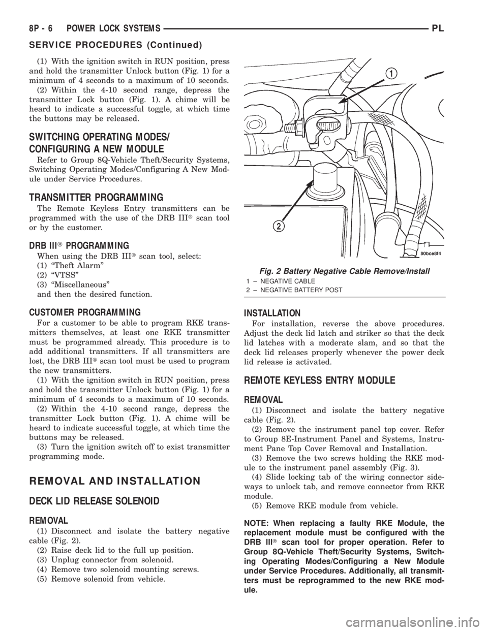
(1) Disconnect and isolate the battery negative
cable (Fig. 2).
(2) Raise deck lid to the full up position.
(3) Unplug connector from solenoid.
(4) Remove two solenoid mounting screws.
(5) Remove solenoid from vehicle.
INSTALLATION
For installation, reverse the above procedures.
Adjust the deck lid latch and striker so that the deck
lid latches with a moderate slam, and so that the
deck lid releases properly whenever the power deck
lid release is activated.
REMOTE KEYLESS ENTRY MODULE
REMOVAL
(1) Disconnect and isolate the battery negative
cable (Fig. 2).
(2) Remove the instrument panel top cover. Refer
to Group 8E-Instrument Panel and Systems, Instru-
ment Pane Top Cover Removal and Installation.
(3) Remove the two screws holding the RKE mod-
ule to the instrument panel assembly (Fig. 3).
(4) Slide locking tab of the wiring connector side-
ways to unlock tab, and remove connector from RKE
module.
(5) Remove RKE module from vehicle.
NOTE: When replacing a faulty RKE Module, the
replacement module must be configured with the
DRB lllTscan tool for proper operation. Refer to
Group 8Q-Vehicle Theft/Security Systems, Switch-
ing Operating Modes/Configuring a New Module
under Service Procedures. Additionally, all transmit-
ters must be reprogrammed to the new RKE mod-
ule.
Fig. 2 Battery Negative Cable Remove/Install
1 ± NEGATIVE CABLE
2 ± NEGATIVE BATTERY POST
8P - 6 POWER LOCK SYSTEMSPL
SERVICE PROCEDURES (Continued)