2000 DODGE NEON ignition switch
[x] Cancel search: ignition switchPage 87 of 1285
RED BRAKE WARNING LAMP
The red BRAKE warning lamp is located in the
instrument panel cluster and illuminates when a low
brake fluid condition occurs or when the parking
brake lever is applied with the ignition key in the
ON position. In addition, the red BRAKE warning
lamp illuminates when the ignition switch is moved
from the OFF to the ON or CRANK position. This is
done to check the bulb's operation.
Problems with this system will generally be of the
type where the warning lamp fails to turn on when it
should, or remains on when it should not.
The red BRAKE warning lamp LED is supplied
with current anytime the ignition switch is ON. The
bulb is illuminated by completing the ground circuit
using any of the following components:
²the brake fluid level switch located in the mas-
ter cylinder reservoir
²the parking brake switch mounted on the park-
ing brake lever (Fig. 10)
²the ignition switch when the ignition switch is
first moved to the ON or CRANK position
²the mechanical instrument cluster (MIC) (with
ABS)
²the ABS electronic brake distribution (EBD)
The brake fluid level switch is located in the brake
fluid reservoir of the master cylinder assembly (Fig.
1). The purpose of the switch is to provide the driver
with an early warning that the brake fluid level inthe master cylinder reservoir has dropped below an
acceptable level.
As the fluid drops below the minimum level, the
fluid level switch closes and grounds the red BRAKE
warning lamp circuit. This turns on the red BRAKE
warning lamp. At this time, the master cylinder fluid
reservoir must be checked and filled to the full mark
with DOT 3 brake fluid. An abnormal loss of brake
fluid in the master cylinder fluid reservoir could be
caused by a leak in the hydraulic system. The entire
brake hydraulic system should be checked for evi-
dence of a leak.
The red BRAKE warning lamp can be turned on by
the MIC in the case where the ABS is experiencing a
problem where the amber ABS warning lamp needs
to be illuminated and cannot. The MIC will then illu-
minate the red BRAKE warning lamp.
BRAKE LAMP SWITCH
The brake lamp switch is located under the instru-
ment panel, at the brake pedal arm (Fig. 13). It con-
trols operation of the vehicle's stop lamps. Also, if the
vehicle is equipped with speed control, the brake
lamp switch will deactivate the speed control when
the brake pedal is depressed.
When the brake pedal is depressed, the brake lamp
switch contacts are closed, completing the circuit to
the stop lamps, thus illuminating the stop lamps and
the center-high-mounted stop lamp (CHMSL).
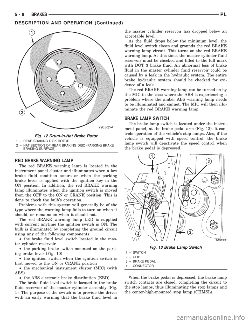
Fig. 12 Drum-In-Hat Brake Rotor
1 ± REAR BRAKING DISK ROTOR
2 ± HAT SECTION OF REAR BRAKING DISC (PARKING BRAKE
BRAKING SURFACE)
Fig. 13 Brake Lamp Switch
1 ± SWITCH
2 ± CLIP
3 ± BRAKE PEDAL
4 ± CONNECTOR
5 - 8 BRAKESPL
DESCRIPTION AND OPERATION (Continued)
Page 146 of 1285
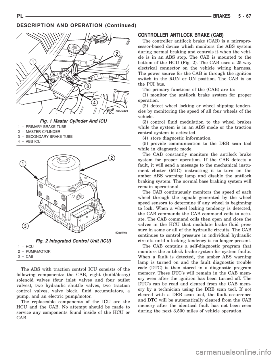
The ABS with traction control ICU consists of the
following components: the CAB, eight (build/decay)
solenoid valves (four inlet valves and four outlet
valves), two hydraulic shuttle valves, two traction
control valves, valve block, fluid accumulators, a
pump, and an electric pump/motor.
The replaceable components of the ICU are the
HCU and the CAB. No attempt should be made to
service any components found inside of the HCU or
CAB.
CONTROLLER ANTILOCK BRAKE (CAB)
The controller antilock brake (CAB) is a micropro-
cessor-based device which monitors the ABS system
during normal braking and controls it when the vehi-
cle is in an ABS stop. The CAB is mounted to the
bottom of the HCU (Fig. 2). The CAB uses a 25-way
electrical connector on the vehicle wiring harness.
The power source for the CAB is through the ignition
switch in the RUN or ON position. The CAB is on
the PCI bus.
The primary functions of the (CAB) are to:
(1) monitor the antilock brake system for proper
operation.
(2) detect wheel locking or wheel slipping tenden-
cies by monitoring the speed of all four wheels of the
vehicle.
(3) control fluid modulation to the wheel brakes
while the system is in an ABS mode or the traction
control system is activated.
(4) store diagnostic information.
(5) provide communication to the DRB scan tool
while in diagnostic mode.
The CAB constantly monitors the antilock brake
system for proper operation. If the CAB detects a
fault, it will send a message to the mechanical instu-
ment cluster (MIC) instructing it to turn on the
amber ABS warning lamp and disable the antilock
braking system. The normal base braking system will
remain operational.
The CAB continuously monitors the speed of each
wheel through the signals generated by the wheel
speed sensors to determine if any wheel is beginning
to lock. When a wheel locking tendency is detected,
the CAB commands the CAB command coils to actu-
ate. The CAB command coils then open and close the
valves in the HCU that modulate brake fluid pres-
sure in some or all of the hydraulic circuits. The CAB
continues to control pressure in individual hydraulic
circuits until a locking tendency is no longer present.
The CAB contains a self-diagnostic program that
monitors the antilock brake system for system faults.
When a fault is detected, the amber ABS warning
lamp is turned on and the fault diagnostic trouble
code (DTC) is then stored in a diagnostic program
memory. These DTC's will remain in the CAB mem-
ory even after the ignition has been turned off. The
DTC's can be read and cleared from the CAB mem-
ory by a technician using the DRB scan tool. If not
cleared with a DRB scan tool, the fault occurrence
and DTC will be automatically cleared from the CAB
memory after the identical fault has not been seen
during the next 3,500 miles of vehicle operation.
Fig. 1 Master Cylinder And ICU
1 ± PRIMARY BRAKE TUBE
2 ± MASTER CYLINDER
3 ± SECONDARY BRAKE TUBE
4 ± ABS ICU
Fig. 2 Integrated Control Unit (ICU)
1 ± HCU
2 ± PUMP/MOTOR
3 ± CAB
PLBRAKES 5 - 67
DESCRIPTION AND OPERATION (Continued)
Page 147 of 1285
CONTROLLER ANTILOCK BRAKE INPUTS
²wheel speed sensors (four)
²stop lamp switch
²ignition switch
²system relay voltage
²ground
²traction control lamp
²diagnostic communication (PCI)
CONTROLLER ANTILOCK BRAKE OUTPUTS
²amber ABS warning lamp actuation (through
MIC)
²red BRAKE warning lamp actuation (through
MIC)
²traction control lamp actuation (through MIC)
²diagnostic communication. (PCI)
HYDRAULIC CONTROL UNIT (HCU)
The hydraulic control unit (HCU) is mounted to
the CAB as part of the ICU (Fig. 2). The HCU con-
trols the flow of brake fluid to the brakes using a
series of valves and accumulators. A pump/motor is
mounted on the HCU to supply build pressure to the
brakes during an ABS stop.
VALVES AND SOLENOIDS
The valve block contains four inlet valves and four
outlet solenoid valves. The inlet valves are spring-
loaded in the open position and the outlet valves are
spring-loaded in the closed position during normal
braking. The fluid is allowed to flow from the master
cylinder to the wheel brakes.
During an ABS stop, these valves cycle to maintain
the proper slip ratio for each wheel. The inlet valve
closes preventing further pressure increase and the
outlet valve opens to provide a path from the wheel
brake to the HCU accumulators and pump/motor.
This releases (decays) pressure from the wheel brake,
thus releasing the wheel from excessive slippage.
Once the wheel is no longer slipping, the outlet valve
is closed and the inlet valve is opened to reapply
(build) pressure.
There are four other valves in the HCU. These four
remaining valves are used for traction control. Two
traction control (TC) valves, mounted in the HCU
valve block, are normally in the open position and
close only when the traction control is applied. There
are also two shuttle valves which control pressure
return to the master cylinder under ABS and traction
control conditions.
These TC valves are used to isolate the rear (non-
driving) wheels of the vehicle from the hydraulic
pressure that the HCU pump/motor is sending to the
front (driving) wheels when traction control is being
applied. The rear brakes need to be isolated from the
master cylinder when traction control is beingapplied so the rear wheels do not drag. For more
information on the TC and shuttle valves, see TRAC-
TION CONTROL SYSTEM in this section.
BRAKE FLUID ACCUMULATORS
There are two fluid accumulators in the HCU: one
for the primary hydraulic circuit, and one for the sec-
ondary hydraulic circuit. Each hydraulic circuit uses
a 3 cc accumulator.
The fluid accumulators temporarily store brake
fluid that is removed from the wheel brakes during
an ABS cycle. This stored fluid is used by the pump/
motor to provide build pressure for the brake hydrau-
lic system. When the antilock stop is complete, the
accumulators are drained by the pump/motor.
There are two noise dampening chambers in the
HCU on this vehicle equipped with traction control.
PUMP/MOTOR
There are two pump assemblies in the HCU: one
for the primary hydraulic circuit, and one for the sec-
ondary hydraulic circuit. Both pumps are driven by a
common electric motor (Fig. 2). This DC-type motor
is integral to the HCU and is controlled by the CAB.
The pump/motor provides the extra amount of
brake fluid needed during antilock braking. Brake
fluid is released to the accumulators when the outlet
valve is opened during an antilock stop. The pump
mechanism consists of two opposing pistons operated
by an eccentric camshaft. In operation, these pistons
are used to purge fluid from the accumulators back
into the master cylinder circuits. When the antilock
stop is complete, the pump/motor drains the accumu-
lators.
The pump motor is also used to build pressure
when the system goes into traction control mode. For
more information, refer to TRACTION CONTROL
SYSTEM in this section.
The CAB may turn on the pump/motor when an
antilock stop is detected. The pump/motor continues
to run during the antilock stop and is turned off after
the stop is complete. Under some conditions, the
pump/motor runs to drain the accumulators during
the next drive-off.
The pump/motor is not a serviceable item; if it
requires replacement, the HCU must be replaced.
ABS FUSES
The ABS fuse and the ABS pump/motor fuse are
located in the power distribution center (PDC). Refer
to the sticker on the inside of the PDC cover for the
location of these fuses. The PDC is located on the
driver's side of the engine compartment between the
back of the battery and the brake master cylinder.
The CAB fuse can be found in the fuse junction
block under the instrument panel.
5 - 68 BRAKESPL
DESCRIPTION AND OPERATION (Continued)
Page 148 of 1285
AMBER ABS WARNING LAMP
The amber ABS warning lamp is located in the
instrument cluster. The purpose of the warning lamp
is discussed in detail below.
When the ignition key is turned to the ON posi-
tion, the amber ABS warning lamp is lit until the
CAB completes its self-tests and turns off the lamp
(approximately 4 seconds). The amber ABS warning
lamp will illuminate when the CAB detects a condi-
tion that results in the shutdown of ABS function.
The CAB sends a message to the mechanical instu-
ment cluster (MIC) instructing it to turn on the
amber ABS warning lamp.
Under most conditions, when the amber ABS warn-
ing lamp is on, only the ABS function of the brake
system is affected; The electronic brake distribution
(EBD), the base brake system and the ability to stop
the vehicle are not affected.
WHEEL SPEED SENSOR (WSS)
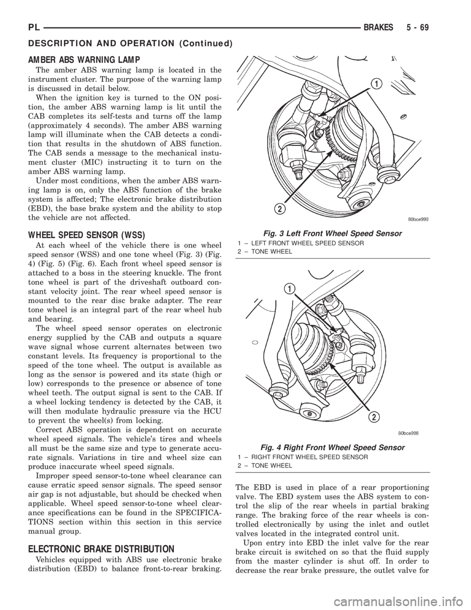
At each wheel of the vehicle there is one wheel
speed sensor (WSS) and one tone wheel (Fig. 3) (Fig.
4) (Fig. 5) (Fig. 6). Each front wheel speed sensor is
attached to a boss in the steering knuckle. The front
tone wheel is part of the driveshaft outboard con-
stant velocity joint. The rear wheel speed sensor is
mounted to the rear disc brake adapter. The rear
tone wheel is an integral part of the rear wheel hub
and bearing.
The wheel speed sensor operates on electronic
energy supplied by the CAB and outputs a square
wave signal whose current alternates between two
constant levels. Its frequency is proportional to the
speed of the tone wheel. The output is available as
long as the sensor is powered and its state (high or
low) corresponds to the presence or absence of tone
wheel teeth. The output signal is sent to the CAB. If
a wheel locking tendency is detected by the CAB, it
will then modulate hydraulic pressure via the HCU
to prevent the wheel(s) from locking.
Correct ABS operation is dependent on accurate
wheel speed signals. The vehicle's tires and wheels
all must be the same size and type to generate accu-
rate signals. Variations in tire and wheel size can
produce inaccurate wheel speed signals.
Improper speed sensor-to-tone wheel clearance can
cause erratic speed sensor signals. The speed sensor
air gap is not adjustable, but should be checked when
applicable. Wheel speed sensor-to-tone wheel clear-
ance specifications can be found in the SPECIFICA-
TIONS section within this section in this service
manual group.
ELECTRONIC BRAKE DISTRIBUTION
Vehicles equipped with ABS use electronic brake
distribution (EBD) to balance front-to-rear braking.The EBD is used in place of a rear proportioning
valve. The EBD system uses the ABS system to con-
trol the slip of the rear wheels in partial braking
range. The braking force of the rear wheels is con-
trolled electronically by using the inlet and outlet
valves located in the integrated control unit.
Upon entry into EBD the inlet valve for the rear
brake circuit is switched on so that the fluid supply
from the master cylinder is shut off. In order to
decrease the rear brake pressure, the outlet valve for
Fig. 3 Left Front Wheel Speed Sensor
1 ± LEFT FRONT WHEEL SPEED SENSOR
2 ± TONE WHEEL
Fig. 4 Right Front Wheel Speed Sensor
1 ± RIGHT FRONT WHEEL SPEED SENSOR
2 ± TONE WHEEL
PLBRAKES 5 - 69
DESCRIPTION AND OPERATION (Continued)
Page 154 of 1285
ABS ELECTRONIC DIAGNOSIS
The following information is presented to give the
technician a general background on the diagnostic
capabilities of the ABS system. Complete electronic
diagnosis of the ABS system used on this vehicle is
covered in the Chassis Diagnostic Procedures manual.
Electronic diagnosis of the ABS system used on
this vehicle is performed using the DRBIIItscan
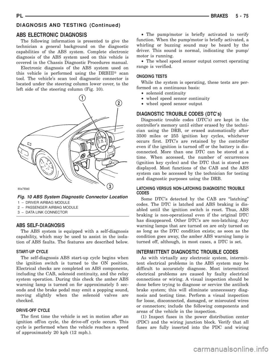
tool. The vehicle's scan tool diagnostic connector is
located under the steering column lower cover, to the
left side of the steering column (Fig. 10).
ABS SELF-DIAGNOSIS
The ABS system is equipped with a self-diagnosis
capability, which may be used to assist in the isola-
tion of ABS faults. The features are described below.
START-UP CYCLE
The self-diagnosis ABS start-up cycle begins when
the ignition switch is turned to the ON position.
Electrical checks are completed on ABS components,
including the CAB, solenoid continuity, and the relay
system operation. During this check the amber ABS
warning lamp is turned on for approximately 5 sec-
onds and the brake pedal may emit a popping sound,
moving slightly when the solenoid valves are
checked.
DRIVE-OFF CYCLE
The first time the vehicle is set in motion after an
ignition off/on cycle, the drive-off cycle occurs. This
cycle is performed when the vehicle reaches a speed
of approximately 20 kph (12 mph.).²The pump/motor is briefly activated to verify
function. When the pump/motor is briefly activated, a
whirling or buzzing sound may be heard by the
driver. This sound is normal, indicating the pump/
motor is running.
²The wheel speed sensor output correct operating
range is verified.
ONGOING TESTS
While the system is operating, these tests are per-
formed on a continuous basis:
²solenoid continuity
²wheel speed sensor continuity
²wheel speed sensor output
DIAGNOSTIC TROUBLE CODES (DTC's)
Diagnostic trouble codes (DTC's) are kept in the
controller's memory until either erased by the techni-
cian using the DRB, or erased automatically after
3500 miles or 255 ignition key cycles, whichever
occurs first. DTC's are retained by the controller
even if the ignition is turned off or the battery is dis-
connected. More than one DTC can be stored at a
time. When accessed, the number of occurrences
(ignition key cycles) and the DTC that is stored are
displayed. Most functions of the CAB and the ABS
system can be accessed by the technician for testing
and diagnostic purposes using the DRB.
LATCHING VERSUS NON-LATCHING DIAGNOSTIC TROUBLE
CODES
Some DTC's detected by the CAB are ªlatchingº
codes. The DTC is latched and ABS braking is dis-
abled until the ignition switch is reset. Thus, ABS
braking is non-operational even if the original DTC
has disappeared. Other DTC's are non-latching. Any
warning lamps that are turned on are only turned on
as long as the DTC condition exists; as soon as the
condition goes away, the amber ABS warning lamp is
turned off, although, in most cases, a DTC is set.
INTERMITTENT DIAGNOSTIC TROUBLE CODES
As with virtually any electronic system, intermit-
tent electrical problems in the ABS system may be
difficult to accurately diagnose. Most intermittent
electrical problems are caused by faulty electrical
connections or wiring. A visual inspection should be
done before trying to diagnose or service the antilock
brake system; this will eliminate unnecessary diag-
nosis and testing time. Perform a visual inspection
for loose, disconnected, damaged, or misrouted wires
or connectors; include the following components and
areas of the vehicle in the inspection.
(1) Inspect fuses in the power distribution center
(PDC) and the wiring junction block. Verify that all
fuses are fully inserted into the PDC and wiring
Fig. 10 ABS System Diagnostic Connector Location
1 ± DRIVER AIRBAG MODULE
2 ± PASSENGER AIRBAG MODULE
3 ± DATA LINK CONNECTOR
PLBRAKES 5 - 75
DIAGNOSIS AND TESTING (Continued)
Page 157 of 1285
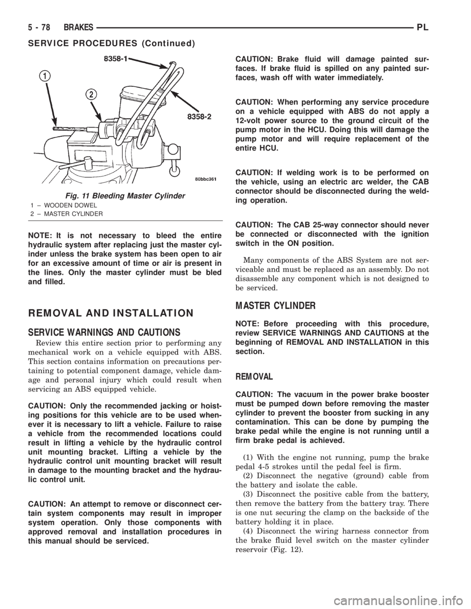
NOTE: It is not necessary to bleed the entire
hydraulic system after replacing just the master cyl-
inder unless the brake system has been open to air
for an excessive amount of time or air is present in
the lines. Only the master cylinder must be bled
and filled.
REMOVAL AND INSTALLATION
SERVICE WARNINGS AND CAUTIONS
Review this entire section prior to performing any
mechanical work on a vehicle equipped with ABS.
This section contains information on precautions per-
taining to potential component damage, vehicle dam-
age and personal injury which could result when
servicing an ABS equipped vehicle.
CAUTION: Only the recommended jacking or hoist-
ing positions for this vehicle are to be used when-
ever it is necessary to lift a vehicle. Failure to raise
a vehicle from the recommended locations could
result in lifting a vehicle by the hydraulic control
unit mounting bracket. Lifting a vehicle by the
hydraulic control unit mounting bracket will result
in damage to the mounting bracket and the hydrau-
lic control unit.
CAUTION: An attempt to remove or disconnect cer-
tain system components may result in improper
system operation. Only those components with
approved removal and installation procedures in
this manual should be serviced.CAUTION: Brake fluid will damage painted sur-
faces. If brake fluid is spilled on any painted sur-
faces, wash off with water immediately.
CAUTION: When performing any service procedure
on a vehicle equipped with ABS do not apply a
12-volt power source to the ground circuit of the
pump motor in the HCU. Doing this will damage the
pump motor and will require replacement of the
entire HCU.
CAUTION: If welding work is to be performed on
the vehicle, using an electric arc welder, the CAB
connector should be disconnected during the weld-
ing operation.
CAUTION: The CAB 25-way connector should never
be connected or disconnected with the ignition
switch in the ON position.
Many components of the ABS System are not ser-
viceable and must be replaced as an assembly. Do not
disassemble any component which is not designed to
be serviced.
MASTER CYLINDER
NOTE: Before proceeding with this procedure,
review SERVICE WARNINGS AND CAUTIONS at the
beginning of REMOVAL AND INSTALLATION in this
section.
REMOVAL
CAUTION: The vacuum in the power brake booster
must be pumped down before removing the master
cylinder to prevent the booster from sucking in any
contamination. This can be done by pumping the
brake pedal while the engine is not running until a
firm brake pedal is achieved.
(1) With the engine not running, pump the brake
pedal 4-5 strokes until the pedal feel is firm.
(2) Disconnect the negative (ground) cable from
the battery and isolate the cable.
(3) Disconnect the positive cable from the battery,
then remove the battery from the battery tray. There
is one nut securing the clamp on the backside of the
battery holding it in place.
(4) Disconnect the wiring harness connector from
the brake fluid level switch on the master cylinder
reservoir (Fig. 12).
Fig. 11 Bleeding Master Cylinder
1 ± WOODEN DOWEL
2 ± MASTER CYLINDER
5 - 78 BRAKESPL
SERVICE PROCEDURES (Continued)
Page 170 of 1285
DRIVE PLATE MISALIGNMENT
Common causes of misalignment are:
²Heat warping
²Mounting drive plate on a dirty crankshaft
flange
²Incorrect bolt tightening
²Improper seating on the crankshaft shoulder
²Loose crankshaft bolts
Clean the crankshaft flange before mounting the
drive plate. Dirt and grease on the flange surface
may misalign the flywheel, causing excessive runout.
Use new bolts when mounting drive plate to crank-
shaft. Tighten drive plate bolts to specified torque
only. Over-tightening can distort the drive plate hub
causing excessive runout.
CLUTCH CHATTER COMPLAINTS
For all clutch chatter complaints, do the following:
(1) Check for loose, misaligned, or broken engine
and transmission mounts. If present, they should be
corrected at this time. Test vehicle for chatter. If
chatter is gone, there is no need to go any further. If
chatter persists:
(2) Check to see if clutch cable routing is correct
and operates smoothly.
(3) Check for loose connections in drive train. Cor-
rect any problems and determine if clutch chatter
complaints have been satisfied. If not:
(4) Remove transaxle. See Group 21, Manual Tran-
saxle for procedure.
(5) Check to see if the release bearing is sticky or
binding. Replace bearing, if needed.
(6) Check linkage for excessive wear on the pivot
stud and fork fingers. Replace all worn parts.
(7) Check clutch assembly for contamination (dirt,
oil). Replace clutch assembly, if required.
(8) Check to see if the clutch disc hub splines are
damaged. Replace with new clutch assembly, if nec-
essary.
(9) Check input shaft splines for damage. Replace,
if necessary.
(10) Check for uneven wear on clutch fingers.
(11) Check for broken clutch cover diaphragm
spring fingers. Replace with new clutch assembly, if
necessary.
CLASH±INTO±REVERSE COMPLAINTS
Certain NV T350 (A-578) manual transaxles are
equipped with a reverse brake. It prevents clash
when shifting into reverse, but only if the vehicle is
not moving. See Group 21, Transaxle for further
diagnosis.
(1) Depress clutch pedal to floor and hold. After
three seconds, shift to reverse. If clash is present,
clutch has excessive spin time, and the reverse brake
may not be functioning.(2) Remove transaxle. See Group 21, Manual Tran-
saxle for procedure.
(3) Check the input shaft spline, clutch disc
splines, and release bearing for dry rust. If present,
clean rust off and apply a light coat of bearing grease
to the input shaft splines. Apply grease on the input
shaft splines only where the clutch disc slides. Verify
that the clutch disc slides freely along the input shaft
spline.
(4) Check to see if the clutch disc hub splines are
damaged, and replace with new clutch assembly if
required.
(5) Check the input shaft for damaged splines.
Replace as necessary.
(6) Check for broken clutch cover diaphragm
spring fingers.
(7) Install clutch assembly and transaxle.
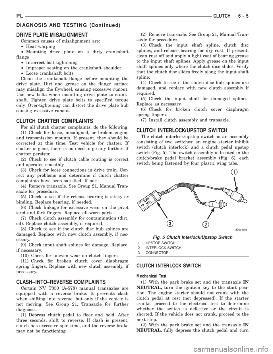
CLUTCH INTERLOCK/UPSTOP SWITCH
The clutch interlock/upstop switch is an assembly
consisting of two switches: an engine starter inhibit
switch (clutch interlock) and a clutch pedal upstop
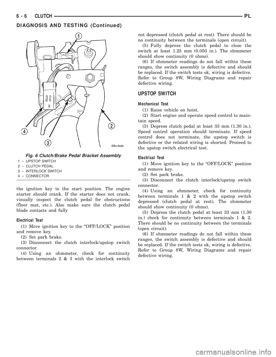
switch (Fig. 5). The switch assembly is located in the
clutch/brake pedal bracket assembly (Fig. 6), each
switch being fastened by four plastic wing tabs.
CLUTCH INTERLOCK SWITCH
Mechanical Test
(1) With the park brake set and the transaxleIN
NEUTRAL,turn the ignition key to the start posi-
tion. The engine starter should not crank with the
clutch pedal at rest (not depressed). If the starter
cranks, proceed to the electrical test to determine
whether the switch is defective or the circuit is
shorted. If the vehicle does not crank, proceed to the
next step.
(2) With the park brake set and the transaxleIN
NEUTRAL,fully depress the clutch pedal and turn
Fig. 5 Clutch Interlock/Upstop Switch
1 ± UPSTOP SWITCH
2 ± INTERLOCK SWITCH
3 ± CONNECTOR
PLCLUTCH 6 - 5
DIAGNOSIS AND TESTING (Continued)
Page 171 of 1285
the ignition key to the start position. The engine
starter should crank. If the starter does not crank,
visually inspect the clutch pedal for obstructions
(floor mat, etc.). Also make sure the clutch pedal
blade contacts and fully
Electrical Test
(1) Move ignition key to the ªOFF/LOCKº position
and remove key.
(2) Set park brake.
(3) Disconnect the clutch interlock/upstop switch
connector.
(4) Using an ohmmeter, check for continuity
between terminals2&3with the interlock switchnot depressed (clutch pedal at rest). There should be
no continuity between the terminals (open circuit).
(5) Fully depress the clutch pedal to close the
switch at least 1.25 mm (0.050 in.). The ohmmeter
should show continuity (0 ohms).
(6) If ohmmeter readings do not fall within these
ranges, the switch assembly is defective and should
be replaced. If the switch tests ok, wiring is defective.
Refer to Group 8W, Wiring Diagrams and repair
defective wiring.
UPSTOP SWITCH
Mechanical Test
(1) Raise vehicle on hoist.
(2) Start engine and operate speed control to main-
tain speed.
(3) Depress clutch pedal at least 33 mm (1.30 in.).
Speed control operation should terminate. If speed
control does not terminate, the upstop switch is
defective or the related wiring is shorted. Proceed to
the upstop switch electrical test.
Electrical Test
(1) Move ignition key to the ªOFF/LOCKº position
and remove key.
(2) Set park brake.
(3) Disconnect the clutch interlock/upstop switch
connector.
(4) Using an ohmmeter, check for continuity
between terminals1&2with the upstop switch
depressed (clutch pedal at rest). The ohmmeter
should show continuity (0 ohms).
(5) Depress the clutch pedal at least 33 mm (1.30
in.) check for continuity between terminals1&2.
There should be no continuity between the terminals
(open circuit).
(6) If ohmmeter readings do not fall within these
ranges, the switch assembly is defective and should
be replaced. If the switch tests ok, wiring is defective.
Refer to Group 8W, Wiring Diagrams and repair
defective wiring.
Fig. 6 Clutch/Brake Pedal Bracket Assembly
1 ± UPSTOP SWITCH
2 ± CLUTCH PEDAL
3 ± INTERLOCK SWITCH
4 ± CONNECTOR
6 - 6 CLUTCHPL
DIAGNOSIS AND TESTING (Continued)