2000 DODGE NEON immobilizer
[x] Cancel search: immobilizerPage 1 of 1285

GROUP TAB LOCATORINIntroductionINaIntroduction0Lubrication and Maintenance2Suspension3Differential and Driveline5Brakes6Clutch7Cooling8ABattery8BStarting8CCharging System8DIgnition System8EInstrument Panel and Systems8EaInstrument Panel and Systems8FAudio System8GHorns8HVehicle Speed Control System8JTurn Signal and Flashers8KWindshield Wipers and Washers8LLamps8LaLamps8MRestraint System8NElectrically Heated Systems8OPower Distribution Systems8PPower Door Locks8QImmobilizer System8SPower Windows8TPower Mirrors8TaPower Mirrors8UChime Warning/Reminder System8WWiring Diagrams - LHD and RHD9Engine11Exhaust System13Frame and Bumpers14Fuel System19Steering21Transaxle22Tires and Wheels23Body24Heating and Air Conditioning24aHeating and Air Conditioning25Emission Control Systems
Page 372 of 1285
VEHICLE THEFT/SECURITY SYSTEM
TABLE OF CONTENTS
page page
DESCRIPTION AND OPERATION
INTRODUCTION..........................1
VEHICLE THEFT/SECURITY SYSTEM (VTSS)...1
SENTRY KEY IMMOBILIZER SYSTEM (SKIS)...2
SENTRY KEY IMMOBILIZER MODULE
(SKIM)................................2
SENTRY KEY IMMOBILIZER SYSTEM
TRANSPONDER.........................3
SENTRY KEY IMMOBILIZER SYSTEM
INDICATOR LAMP.......................4
TRIGGERING THE VTSS....................4
DIAGNOSIS AND TESTING
SENTRY KEY IMMOBILIZER SYSTEM.........4
VEHICLE THEFT/SECURITY SYSTEM (VTSS)...5SERVICE PROCEDURES
SENTRY KEY IMMOBILIZER SYSTEM
INITIALIZATION.........................5
SENTRY KEY IMMOBILIZER SYSTEM
TRANSPONDER PROGRAMMING...........5
SWITCHING OPERATING MODES/
CONFIGURING A NEW MODULE............6
REMOVAL AND INSTALLATION
DOOR CYLINDER LOCK SWITCH.............7
HOOD AJAR SWITCH......................7
SENTRY KEY IMMOBILIZER MODULE
(SKIM)................................7
VEHICLE THEFT/SECURITY SYSTEM DECK
LID SECURITY (KNOCK OUT) SWITCH.......8
DESCRIPTION AND OPERATION
INTRODUCTION
The Vehicle Theft/Security System (VTSS) is
designed to protect against whole vehicle theft. The
system monitors vehicle doors, hood, trunk key cylin-
der, and ignition for unauthorized operation.
The VTSS activates:
²Sounding of the horn.
²Flashing of the park lamps.
²Flashing of the headlamps.
The RKE Module has three modes of operation
including customer usage mode, dealer lot storage
mode, and shipping mode. The customer usage mode
provides full functionality of the module and is the
mode in which the RKE Module should be operating
when used by the customer. Dealer lot storage mode
and shipping mode are reduced power modes meant
to extend vehicle battery life during shipping and
storage in the dealer lot. Dealer lot storage mode pro-
vides limited VTSS and power door lock functions,
and disables the Remote Keyless Entry (RKE) func-
tions. This mode is intended to be used when the
vehicle is on the dealer lot to provide VTSS coverage
of the vehicle while minimizing battery drain. Ship-
ping mode disables all normal functions of the mod-
ule with the exception of communications over the
vehicle's PCI bus, and is intended to be used when
the vehicle is shipped from the assembly plant. The
dealer must remove the module from shipping modeand place it into either the dealer lot storage or cus-
tomer usage modes of operation.
NOTE: The dealer must remove the module from
ªShip Modeº and place the RKE Module into either
the ªDealer Lotº storage or ªCustomer Usageº
modes of operation after receiving the vehicle from
the assembly plant. Refer to Switching Operating
Modes/Configuring a New Module under Service
Procedures in this section.
VEHICLE THEFT/SECURITY SYSTEM (VTSS)
In the customer usage mode of operation, the sys-
tem is armed when the vehicle is locked using the:
²Power door lock switches.
²Remote Keyless Entry (RKE) transmitter.
After the vehicle is locked and the last door is
closed, the circular red VTSS indicator in the instru-
ment cluster will flash quickly for 16 seconds, indi-
cating that arming is in progress. If no monitored
systems are activated during this period (excluding
the hood and trunk key cylinder), the system will
arm. After 16 seconds, the LED will continue to flash
at a slower rate indicating the system is armed.
If the hood ajar switch and/or trunk key cylinder
switch(s) are not sensed by the system, the indicator
LED will remain lit during the arming process,
although the system will still arm. If the VTSS indi-
cator does not illuminate at all upon door closing it
indicates that the system is not arming.
PLVEHICLE THEFT/SECURITY SYSTEM 8Q - 1
Page 373 of 1285
VTSS disarming occurs upon normal vehicle entry
by unlocking either door via the key cylinders or
RKE transmitter, or by starting the vehicle with a
valid Sentry Key. This disarming will also halt the
alarm once it has been activated.
A tamper alert exists to notify the driver that the
system had been activated. This alert consists of 3
horn pulses when the vehicle is disarmed.
The VTSS will not arm by mechanically locking the
vehicle doors. This will manually override the sys-
tem.
In the dealer lot storage mode of operation, all of
the above descriptions of the VTSS are true with the
following exceptions:
²Remote Keyless Entry functions are disabled,
and cannot be used for arming/disarming the VTSS.
²The VTSS indicator is non-operational.
SENTRY KEY IMMOBILIZER SYSTEM (SKIS)
The Sentry Key Immobilizer System (SKIS) is
designed to provide passive protection against unau-
thorized vehicle use by preventing the engine from
operating while the system is armed. The primary
components of this system are the Sentry Key Immo-
bilizer Module (SKIM), the Sentry Key transponder,
the Vehicle Theft/Security System (VTSS) indicator
LED, and the Powertrain Control Module (PCM).
The SKIM is installed on the steering column near
the ignition lock cylinder. The transponder is located
under the molded rubber cap on the head of the igni-
tion key. The VTSS indicator LED is located in the
instrument cluster.
The SKIS includes three valid Sentry Key tran-
sponders from the factory, one being a valet key. This
is so the customer can self program new keys if one
is lost. If the customer wishes, additional non-coded
blank Sentry Keys are available. These blank keys
can be cut to match a valid ignition key, but the
engine will not start unless the key transponder is
also programmed to the vehicle. The SKIS will recog-
nize no more than eight valid Sentry Key transpon-
ders at any one time.
The SKIS performs a self-test each time the igni-
tion switch is turned to the ON position, and will
store Diagnostic Trouble Codes (DTC's) if a system
malfunction is detected. The SKIS can be diagnosed,
and any stored DTC can be retrieved using a DRB
llltscan tool as described in the proper Body Diag-
nostic Procedures Manual.
SENTRY KEY IMMOBILIZER MODULE (SKIM)
The Sentry Key Immobilizer Module (SKIM) (Fig.
1) contains a Radio Frequency (RF) transceiver and a
central processing unit, which includes the Sentry
Key Immobilizer System (SKIS) program logic. The
SKIS programming enables the SKIM to programand retain in memory the codes of at least two, but
no more than eight electronically coded Sentry Key
transponders. The SKIS programming also enables
the SKIM to communicate over the Programmable
Communication Interface (PCI) bus network with the
Powertrain Control Module (PCM), the instrument
cluster and/or the DRB IIItscan tool.
The SKIM transmits and receives RF signals
through a tuned antenna enclosed within a molded
plastic ring formation that is integral to the SKIM
housing. When the SKIM is properly installed on the
steering column, the antenna ring is oriented around
the circumference of the ignition lock cylinder hous-
ing (Fig. 1). This antenna ring must be located
within eight millimeters (0.31 inches) of the Sentry
Key in order to ensure proper RF communication
between the SKIM and the Sentry Key transponder.
For added system security, each SKIM is pro-
grammed with a unique ªSecret Keyº code and a
security code. The SKIM keeps the ªSecret Keyº code
in memory and sends the code over the CCD data
bus to the PCM, which also keeps this code in its
memory. The SKIM also sends the ªSecret Keyº code
to each of the programmed Smart Key transponders.
The security code is used by the assembly plant to
access the SKIS for initialization, or by the dealer
technician to access the system for service. The
SKIM also stores in its memory the Vehicle Identifi-
cation Number (VIN), which it learns through a PCI
bus message from the PCM during initialization.
The SKIM and the PCM both use software that
includes a rolling code algorithm strategy, which
helps to reduce the possibility of unauthorized SKIS
Fig. 1 Sentry Key Immobilizer Module (SKIM)
Location
1 ± STEERING COLUMN
2 ± SKIM ELECTRICAL CONNECTOR
3 ± SKIM
8Q - 2 VEHICLE THEFT/SECURITY SYSTEMPL
DESCRIPTION AND OPERATION (Continued)
Page 374 of 1285
disarming. The rolling code algorithm ensures secu-
rity by preventing an override of the SKIS through
the unauthorized substitution of the SKIM or the
PCM. However, the use of this strategy also means
that replacement of either the SKIM or the PCM
units will require a system initialization procedure to
restore system operation.
When the ignition switch is turned to the ON or
START positions, the SKIM transmits an RF signal
to excite the Sentry Key transponder. The SKIM then
listens for a return RF signal from the transponder
of the Sentry Key that is inserted in the ignition lock
cylinder. If the SKIM receives an RF signal with
valid ªSecret Keyº and transponder identification
codes, the SKIM then sends a ªvalid keyº message to
the PCM over the PCI bus. If the SKIM receives an
invalid RF signal or no response, it sends ªinvalid
keyº messages to the PCM. The PCM will enable or
disable engine operation based upon the status of the
SKIM messages.
The SKIM also sends messages to the instrument
cluster over the PCI bus network to control the VTSS
indicator LED. The SKIM sends messages to the
instrument cluster to turn the LED on for about
three seconds when the ignition switch is turned to
the ON position as a bulb test. After completion of
the bulb test, the SKIM sends bus messages to keep
the LED off for a duration of about one second. Then
the SKIM sends messages to turn the LED on or off
based upon the results of the SKIS self-tests. If the
VTSS indicator LED comes on and stays on after the
bulb test, it indicates that the SKIM has detected a
system malfunction and/or that the SKIS has become
inoperative.
If the SKIM detects an invalid key when the igni-
tion switch is turned to the ON position, it sends
messages to the instrument cluster to flash the VTSS
indicator LED. The SKIM can also send messages to
the instrument cluster to flash the LED and to gen-
erate a single audible chime tone. These functions
serve as an indication to the customer that the SKIS
has been placed in its ªCustomer Learnº program-
ming mode. See Sentry Key Immobilizer System
Transponder Programming in this group for more
information on the ªCustomer Learnº programming
mode.
For diagnosis or initialization of the SKIM and the
PCM, a DRB IIItscan tool and the proper Body
Diagnostic Procedures Manual are required. The
SKIM cannot be repaired, and if faulty or damaged,
the unit must be replaced.
SENTRY KEY IMMOBILIZER SYSTEM
TRANSPONDER
The Sentry Key Immobilizer System (SKIS) uses a
transponder that is integral to each of three ignitionkey that are supplied with the vehicle when it is
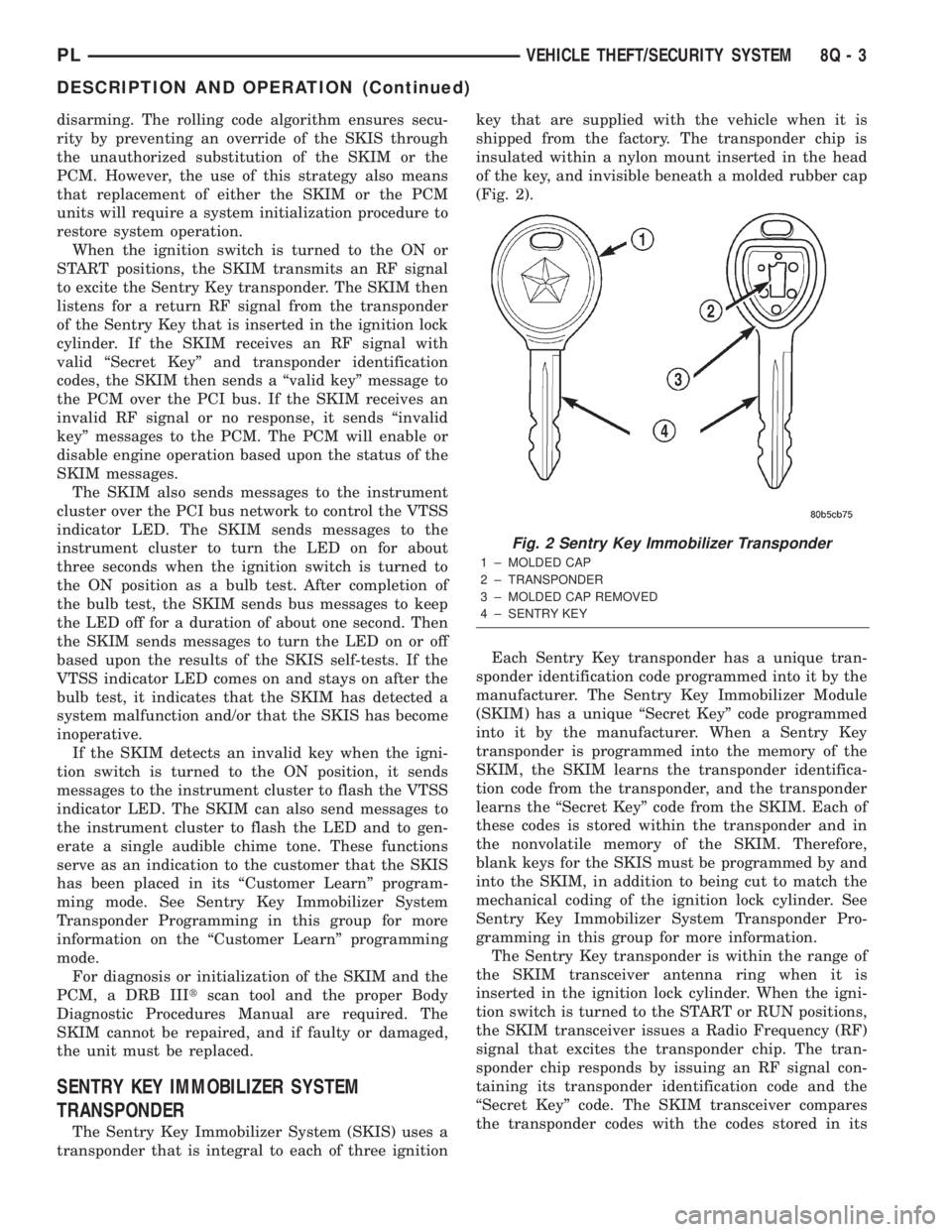
shipped from the factory. The transponder chip is
insulated within a nylon mount inserted in the head
of the key, and invisible beneath a molded rubber cap
(Fig. 2).
Each Sentry Key transponder has a unique tran-
sponder identification code programmed into it by the
manufacturer. The Sentry Key Immobilizer Module
(SKIM) has a unique ªSecret Keyº code programmed
into it by the manufacturer. When a Sentry Key
transponder is programmed into the memory of the
SKIM, the SKIM learns the transponder identifica-
tion code from the transponder, and the transponder
learns the ªSecret Keyº code from the SKIM. Each of
these codes is stored within the transponder and in
the nonvolatile memory of the SKIM. Therefore,
blank keys for the SKIS must be programmed by and
into the SKIM, in addition to being cut to match the
mechanical coding of the ignition lock cylinder. See
Sentry Key Immobilizer System Transponder Pro-
gramming in this group for more information.
The Sentry Key transponder is within the range of
the SKIM transceiver antenna ring when it is
inserted in the ignition lock cylinder. When the igni-
tion switch is turned to the START or RUN positions,
the SKIM transceiver issues a Radio Frequency (RF)
signal that excites the transponder chip. The tran-
sponder chip responds by issuing an RF signal con-
taining its transponder identification code and the
ªSecret Keyº code. The SKIM transceiver compares
the transponder codes with the codes stored in its
Fig. 2 Sentry Key Immobilizer Transponder
1 ± MOLDED CAP
2 ± TRANSPONDER
3 ± MOLDED CAP REMOVED
4 ± SENTRY KEY
PLVEHICLE THEFT/SECURITY SYSTEM 8Q - 3
DESCRIPTION AND OPERATION (Continued)
Page 375 of 1285
memory to determine whether a valid key is in the
ignition lock cylinder.
The Sentry Key transponder cannot be repaired
and, if faulty or damaged, it must be replaced.
SENTRY KEY IMMOBILIZER SYSTEM
INDICATOR LAMP
The Sentry Key Immobilizer System (SKIS) uses
the Vehicle Theft Security System (VTSS) indicator
LED to give an indication when the SKIS is faulty or
when the vehicle has been immobilized due to the
use of an invalid ignition key. The LED is controlled
by the instrument cluster circuitry based upon mes-
sages received from the Sentry Key Immobilizer
Module (SKIM) through the Body Control Module
(BCM) on the Programmable Communication Inter-
face (PCI) bus.
The SKIM sends messages to the instrument clus-
ter, via the BCM, to turn the LED on for about three
seconds when the ignition switch is turned to the ON
position as a bulb test. After completion of the bulb
test, the SKIM sends PCI bus messages to keep the
LED off for a duration of about one second. Then the
SKIM sends messages to the instrument cluster cir-
cuitry to turn the LED on or off based upon the
results of the SKIS self-tests. If the VTSS indicator
LED comes on and stays on after the bulb test, it
indicates that the SKIM has detected a system mal-
function and/or that the SKIS has become inopera-
tive. If the SKIM detects an invalid key when the
ignition switch is turned to the ON position, it sends
messages to the instrument cluster to flash the VTSS
indicator LED.
The SKIM can also send messages to the instru-
ment cluster to flash the LED and to generate a sin-
gle audible chime tone. These functions serve as an
indication to the customer that the SKIS has been
placed in its ªCustomer Learnº programming mode.
See Sentry Key Immobilizer System Transponder
Programming in this group for more information on
the ªCustomer Learnº programming mode.
The VTSS indicator LED uses a replaceable Light
Emitting Diode (LED) on the instrument cluster elec-
tronic circuit board. Refer to Group 8E - Instrument
Panel Systems for Cluster Lamp Removal and Instal-
lation. If the VTSS indicator LED comes on and
stays on after the bulb test function, diagnosis of the
SKIS should be performed with a DRB IIItscan tool
and the proper Body Diagnostic Procedures Manual.
TRIGGERING THE VTSS
After the VTSS is armed, any of the following will
trigger the system:
²Opening any door.
²Opening the hood.
²Removing the trunk lock cylinder.²Turning the ignition to the RUN/START position
with an invalid Sentry Key.
NOTE: The ignition switch can be turned to the
accessory position without triggering the alarm sys-
tem.
DIAGNOSIS AND TESTING
SENTRY KEY IMMOBILIZER SYSTEM
WARNING: ON VEHICLES EQUIPPED WITH AIR-
BAGS, REFER TO GROUP 8M - PASSIVE
RESTRAINT SYSTEMS BEFORE ATTEMPTING ANY
STEERING WHEEL, STEERING COLUMN, OR
INSTRUMENT PANEL COMPONENT DIAGNOSIS OR
SERVICE. FAILURE TO TAKE THE PROPER PRE-
CAUTIONS COULD RESULT IN ACCIDENTAL AIR-
BAG DEPLOYMENT AND POSSIBLE PERSONAL
INJURY.
NOTE: The following tests may not prove conclu-
sive in the diagnosis of this system. The most reli-
able, efficient, and accurate means to diagnose the
Sentry Key Immobilizer System (SKIS) involves the
use of a DRB lllTscan tool and the proper Body
Diagnostic Procedures Manual.
The Sentry Key Immobilizer System (SKIS) and
the Programmable Communication Interface (PCI)
bus network should be diagnosed using a DRB lllt
scan tool. The DRB IIItwill allow confirmation that
the PCI bus is functional, that the Sentry Key Immo-
bilizer Module (SKIM) is placing the proper messages
on the PCI bus, and that the Powertrain Control
Module (PCM) and the instrument cluster are receiv-
ing the PCI bus messages. Refer to the proper Body
Diagnostic Procedures Manual. Refer to Group
8W-Wiring Diagrams for complete circuit descriptions
and diagrams.
(1) Check the fuses in the fuse block. If OK, go to
Step 2. If not OK, repair the shorted circuit or com-
ponent as required and replace the faulty fuse.
(2) Disconnect and isolate the battery negative
cable (Fig. 3). Unplug the wire harness connector at
the SKIM. Check for continuity between the ground
circuit cavity of the SKIM wire harness connector
and a good ground. There should be continuity. If
OK, go to Step 3. If not OK, repair the open circuit to
ground as required.
(3) Connect the battery negative cable. Check for
battery voltage at the fused B(+) circuit cavity of the
SKIM wire harness connector. If OK, go to Step 4. If
not OK, repair the open circuit to the fuse in the fuse
block as required.
8Q - 4 VEHICLE THEFT/SECURITY SYSTEMPL
DESCRIPTION AND OPERATION (Continued)
Page 376 of 1285

(4) Turn the ignition switch to the ON position.
Check for battery voltage at the fused ignition switch
output (run/start) circuit cavity of the SKIM wire
harness connector. If OK, use a DRB IIItscan tool
and the proper Body Diagnostic Procedures Manual
to complete the diagnosis of the SKIS. If not OK,
repair the open circuit to the fuse in the fuse block as
required.
VEHICLE THEFT/SECURITY SYSTEM (VTSS)
To diagnose the Vehicle Theft/Security System
(VTSS), use a DRB IIItscan tool and the proper
Body Diagnostic Procedures Manual.
SERVICE PROCEDURES
SENTRY KEY IMMOBILIZER SYSTEM
INITIALIZATION
The Sentry Key Immobilizer System (SKIS) initial-
ization should be performed following a Sentry Key
Immobilizer Module (SKIM) replacement.
It can be summarized by the following:
(1) Obtain the vehicles unique PIN number
assigned to it's original SKIM from the vehicle
owner, the vehicle's invoice or from Daimler-
Chrysler's Customer Center.
(2) With the DRB IIItscan tool, select ªTheft
Alarm,º ªSKIM,º Miscellaneous.º Select ªSKIM Mod-ule Replacedº function and the DRB llltwill prompt
you through the following steps.
(3) Enter secured access mode using the unique
four digit PIN number.
(4) Program the vehicle's VIN number into the
SKIM's memory.
(5) Program the country code into the SKIM's
memory (U. S.).
(6) Transfer the vehicle's unique Secret Key data
from the PCM. This process will require the SKIM to
be insecured access mode. The PIN number must
be entered into the DRB IIItbefore the SKIM will
entersecured access mode. Oncesecured access
modeis active, the SKIM will remain in that mode
for 60 seconds.
(7) Program all customer keys into the SKIM's
memory. This required that the SKIM be insecured
access modeThe SKIM will immediately exit
secured access modeafter each key is pro-
grammed.
NOTE: SECURED ACCESS MODE is not required to
query the programmed status of the key.
NOTE: If a PCM is replaced, the unique ªSecret
Keyº data must be transferred from the SKIM to the
PCM. This procedure requires the SKIM to be
placed in SECURED ACCESS MODE using the four
digit PIN code.
SENTRY KEY IMMOBILIZER SYSTEM
TRANSPONDER PROGRAMMING
Three programmed Sentry Key transponders are
included with the Sentry Key Immobilizer System
(SKIS) when it is shipped from the factory. The Sen-
try Key Immobilizer Module (SKIM) can be pro-
grammed to recognize up to five additional
transponders, for a total of eight Sentry Keys. The
following ªCustomer Learnº programming procedure
for the programming of additional transponders
requires access to at least two of the valid Sentry
Keys. If two valid Sentry Keys are not available, Sen-
try Key programming will require the use of a DRB
IIItscan tool.
CUSTOMER LEARN PROGRAMMING
(1) Obtain the additional Sentry Key transponder
blank(s) that are to be programmed for the vehicle.
Cut the additional Sentry Key transponder blanks to
match the ignition lock cylinder mechanical key
codes.
(2) Insert one of the two valid Sentry Key tran-
sponders into the ignition switch and turn the igni-
tion switch to the ON position.
Fig. 3 Battery Negative Cable Remove/Install
1 ± NEGATIVE CABLE
2 ± NEGATIVE BATTERY POST
PLVEHICLE THEFT/SECURITY SYSTEM 8Q - 5
DIAGNOSIS AND TESTING (Continued)
Page 377 of 1285
(3) After the ignition switch has been in the ON
position for about three seconds, but no more than
fifteen seconds, cycle the ignition switch back to the
OFF position. Replace the first valid Sentry Key in
the ignition lock cylinder with the second valid Sen-
try Key and turn the ignition switch back to the ON
position. Both operations must be performed within
15 seconds.
(4) About ten seconds after the completion of Step
3, the VTSS indicator LED will start to flash and a
single audible chime tone will sound to indicate that
the system has entered the ªCustomer Learnº pro-
gramming mode.
(5) Within about fifty seconds of entering the ªCus-
tomer Learnº programming mode, turn the ignition
switch to the OFF position, replace the valid Sentry
Key with a blank Sentry Key transponder, and turn
the ignition switch back to the ON position.
(6) About ten seconds after the completion of Step
5, a single audible chime tone will sound and the
VTSS indicator LED will stop flashing and stay on
solid for about three seconds to indicate that the
blank Sentry Key transponder has been successfully
programmed. The SKIS will immediately return to
normal system operation following exit from the
ªCustomer Learnº programming mode.
(7) Go back to Step 2 and repeat this process for
each additional Sentry Key transponder blank to be
programmed.
If any of the above steps is not completed in the
proper sequence, or within the allotted time, the
SKIS will automatically exit the ªCustomer Learnº
programming mode. The SKIS will also automatically
exit the ªCustomer Learnº programming mode if it
sees a non-blank Sentry Key transponder when it
should see a blank, if it has already programmed
eight valid Sentry Keys, or if the ignition switch is
turned to the OFF position for more than about fifty
seconds.
PROGRAMMING BLANK SENTRY KEY
TRANSPONDERS WITH A DRB lllTSCAN TOOL
When programming a blank Sentry Key transpon-
der, the key blank must first be cut to match the
ignition lock cylinder. It will also be necessary to
enter the vehicle's four digit PIN code into the DRB
IIItscan tool to enter the Sentry Key Immobilizer
Module's (SKIM's) secured access mode.
NOTE: Once a Sentry Key is programmed to a par-
ticular vehicle, it cannot be transferred to another
vehicle.
Insert the blank key into the ignition and turn it to
the RUN position. Using the DRB IIItscan tool,
select ªTheft Alarm,º then ªSKIM,º then ªMiscella-
neous.º Select ªProgram New Key.º Enter the fourdigit PIN code using the DRB IIIt. When program-
ming is completed, the SKIM will exit secured access
mode and display the status of the key. One of five
different status messages may be displayed as fol-
lows:
²ªProgramming Successfulº is displayed if SKIM
Sentry Key programming succeeds.
²ªLearned Key in Ignitionº is displayed if the key
in the ignition has already been programmed into
that vehicle's SKIM.
²ª8 Keys Already Learned (At The Maximum)
Programming Not Doneº is displayed if eight keys
have already been programmed into the SKIM. In
this case, if a new key needs to be added due to a
lost or defective key, the ªErase All Keysº function
(requires entering secured access mode) has to be
performed. Then the customer is seven keys plus the
new key MUST be reprogrammed into the SKIM.
²ªProgramming Not Attemptedº is displayed after
an ªErase All Keysº function is executed.
²ªProgramming Key Failedº is displayed if fur-
ther diagnosis is required.
²To learn additional keys, turn the ignition OFF,
remove the learned key, and insert the next new
blank key. Turn ignition to the RUN position and re-
enter the secured access mode function and repeat
the ªProgram New Keyº procedure outlined above.
SWITCHING OPERATING MODES/
CONFIGURING A NEW MODULE
To switch operating modes or to configure a new
module, a DRB IIItscan tool must be used.
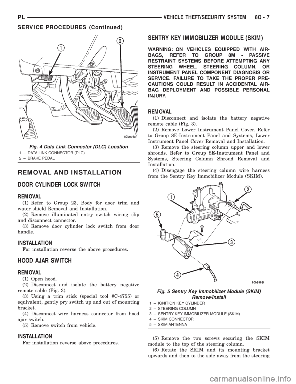
(1) Hook up the DRB IIItscan tool to the Data
Link Connector (DLC) (Fig. 4).
(2) With the key in the ignition, turn the key to
the RUN position.
(3) After the DRB IIItscan tool initialization, per-
form the following:
(a) Select ªTheft Alarm.º
(b) Select ªVTSS.º
(c) Select ªMiscellaneous.º
(4) Once in the ªMiscellaneousº screen:
(a) If you wish to configure a new module, select
ªConfigure Module.º
(b) If you wish to put the module into customer
usage mode, select ªEnable VTSS.º
(c) If you wish to put the module into dealer lot
mode, select ªDealer Lot.º
8Q - 6 VEHICLE THEFT/SECURITY SYSTEMPL
SERVICE PROCEDURES (Continued)
Page 378 of 1285
REMOVAL AND INSTALLATION
DOOR CYLINDER LOCK SWITCH
REMOVAL
(1) Refer to Group 23, Body for door trim and
water shield Removal and Installation.
(2) Remove illuminated entry switch wiring clip
and disconnect connector.
(3) Remove door cylinder lock switch from door
handle.
INSTALLATION
For installation reverse the above procedures.
HOOD AJAR SWITCH
REMOVAL
(1) Open hood.
(2) Disconnect and isolate the battery negative
remote cable (Fig. 3).
(3) Using a trim stick (special tool #C-4755) or
equivalent, gently pry switch up and out of mounting
bracket.
(4) Disconnect wire harness connector from hood
ajar switch.
(5) Remove switch from vehicle.
INSTALLATION
For installation reverse above procedures.
SENTRY KEY IMMOBILIZER MODULE (SKIM)
WARNING: ON VEHICLES EQUIPPED WITH AIR-
BAGS, REFER TO GROUP 8M - PASSIVE
RESTRAINT SYSTEMS BEFORE ATTEMPTING ANY
STEERING WHEEL, STEERING COLUMN, OR
INSTRUMENT PANEL COMPONENT DIAGNOSIS OR
SERVICE. FAILURE TO TAKE THE PROPER PRE-
CAUTIONS COULD RESULT IN ACCIDENTAL AIR-
BAG DEPLOYMENT AND POSSIBLE PERSONAL
INJURY.
REMOVAL
(1) Disconnect and isolate the battery negative
remote cable (Fig. 3).
(2) Remove Lower Instrument Panel Cover. Refer
to Group 8E-Instrument Panel and Systems, Lower
Instrument Panel Cover Removal and Installation.
(3) Remove the steering column upper and lower
shrouds. Refer to Group 8E-Inatrument Panel and
Systems, Steering Column Shroud Removal and
Installation.
(4) Disengage the steering column wire harness
from the Sentry Key Immobilizer Module (SKIM).
(5) Remove the two screws securing the SKIM
module to the top of the steering column.
(6) Rotate the SKIM and its mounting bracket
upwards and then to the side away from the steering
Fig. 4 Data Link Connector (DLC) Location
1 ± DATA LINK CONNECTOR (DLC)
2 ± BRAKE PEDAL
Fig. 5 Sentry Key Immobilizer Module (SKIM)
Remove/Install
1 ± IGNITION KEY CYLINDER
2 ± STEERING COLUMN
3 ± SENTRY KEY IMMOBILIZER MODULE (SKIM)
4 ± SKIM CONNECTOR
5 ± SKIM ANTENNA
PLVEHICLE THEFT/SECURITY SYSTEM 8Q - 7
SERVICE PROCEDURES (Continued)