2000 DODGE NEON wheel bolts
[x] Cancel search: wheel boltsPage 15 of 1285
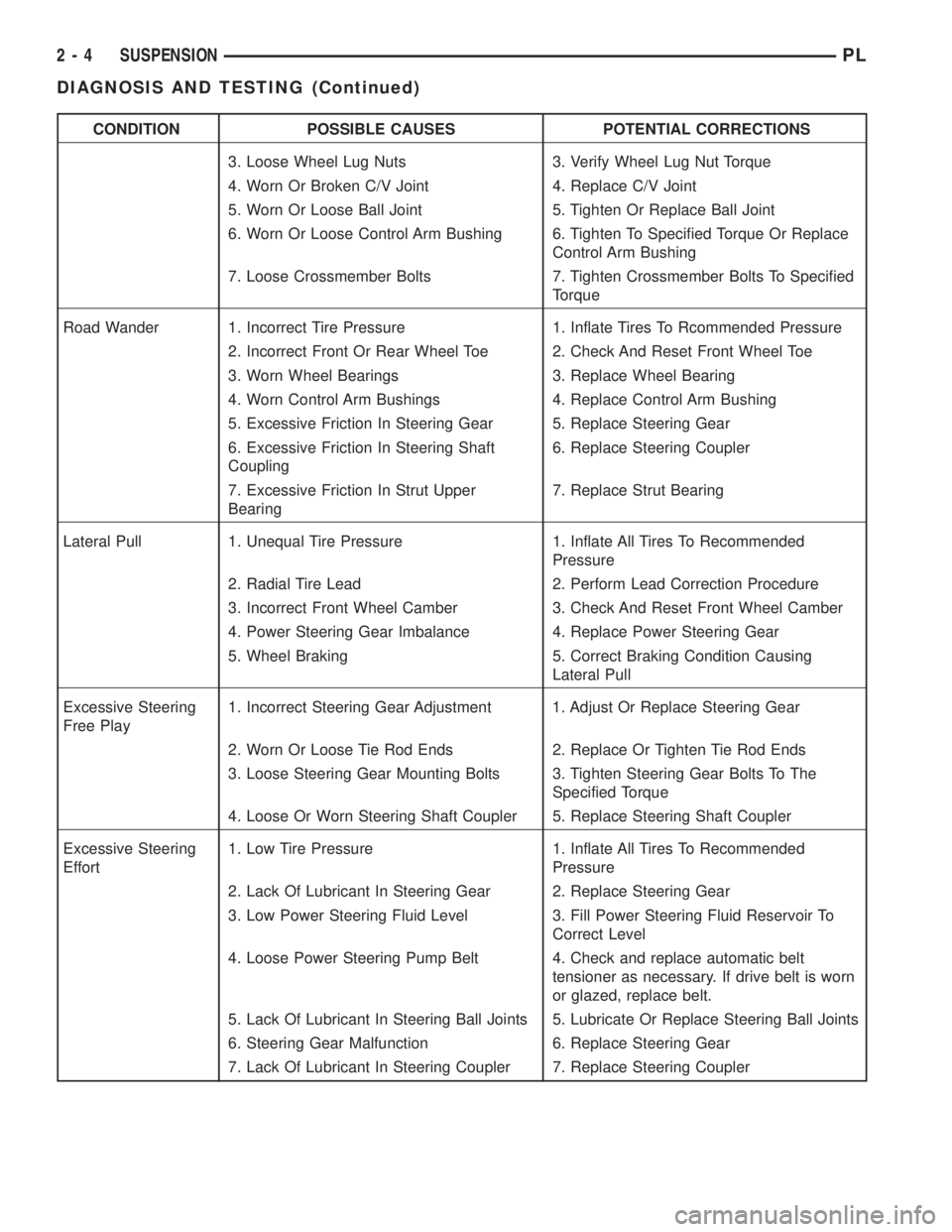
CONDITION POSSIBLE CAUSES POTENTIAL CORRECTIONS
3. Loose Wheel Lug Nuts 3. Verify Wheel Lug Nut Torque
4. Worn Or Broken C/V Joint 4. Replace C/V Joint
5. Worn Or Loose Ball Joint 5. Tighten Or Replace Ball Joint
6. Worn Or Loose Control Arm Bushing 6. Tighten To Specified Torque Or Replace
Control Arm Bushing
7. Loose Crossmember Bolts 7. Tighten Crossmember Bolts To Specified
Torque
Road Wander 1. Incorrect Tire Pressure 1. Inflate Tires To Rcommended Pressure
2. Incorrect Front Or Rear Wheel Toe 2. Check And Reset Front Wheel Toe
3. Worn Wheel Bearings 3. Replace Wheel Bearing
4. Worn Control Arm Bushings 4. Replace Control Arm Bushing
5. Excessive Friction In Steering Gear 5. Replace Steering Gear
6. Excessive Friction In Steering Shaft
Coupling6. Replace Steering Coupler
7. Excessive Friction In Strut Upper
Bearing7. Replace Strut Bearing
Lateral Pull 1. Unequal Tire Pressure 1. Inflate All Tires To Recommended
Pressure
2. Radial Tire Lead 2. Perform Lead Correction Procedure
3. Incorrect Front Wheel Camber 3. Check And Reset Front Wheel Camber
4. Power Steering Gear Imbalance 4. Replace Power Steering Gear
5. Wheel Braking 5. Correct Braking Condition Causing
Lateral Pull
Excessive Steering
Free Play1. Incorrect Steering Gear Adjustment 1. Adjust Or Replace Steering Gear
2. Worn Or Loose Tie Rod Ends 2. Replace Or Tighten Tie Rod Ends
3. Loose Steering Gear Mounting Bolts 3. Tighten Steering Gear Bolts To The
Specified Torque
4. Loose Or Worn Steering Shaft Coupler 5. Replace Steering Shaft Coupler
Excessive Steering
Effort1. Low Tire Pressure 1. Inflate All Tires To Recommended
Pressure
2. Lack Of Lubricant In Steering Gear 2. Replace Steering Gear
3. Low Power Steering Fluid Level 3. Fill Power Steering Fluid Reservoir To
Correct Level
4. Loose Power Steering Pump Belt 4. Check and replace automatic belt
tensioner as necessary. If drive belt is worn
or glazed, replace belt.
5. Lack Of Lubricant In Steering Ball Joints 5. Lubricate Or Replace Steering Ball Joints
6. Steering Gear Malfunction 6. Replace Steering Gear
7. Lack Of Lubricant In Steering Coupler 7. Replace Steering Coupler
2 - 4 SUSPENSIONPL
DIAGNOSIS AND TESTING (Continued)
Page 17 of 1285
SPECIFICATIONS in this section of this service
manual group.
(4) If the rear alignment is out of specification,
adjust it first before proceeding to the front.
CAMBER AND CASTER
Front and rear camber and caster settings on this
vehicle are determined at the time the vehicle is
designed, by the location of the vehicle's suspension
components. This is referred to as Net Build. The
result is no required adjustment of camber and
caster after the vehicle is built or when servicing the
suspension components. Thus, when performing a
wheel alignment, caster and camber are not normally
considered adjustable angles. Camber and caster
should be checked to ensure they meet vehicle speci-
fications.
If either front or rear camber is found not to meet
alignment specifications, it can be adjusted using an
available camber adjustment bolt package. Before
installing a camber adjustment bolt package on a
vehicle found to be outside the specifications, inspect
the suspension components for any signs of damage
or bending.
No adjustment can be made to the caster setting
on this vehicle. If the vehicle's caster is not within
alignment specifications, check for damaged suspen-
sion components or body parts.
CAUTION: Do not attempt to adjust the vehicles
wheel alignment by heating or bending any of the
suspension components.
CAMBER ADJUSTMENT BOLT PACKAGE INSTALLATION
NOTE: The following procedure should only be
used on vehicles without the ACR competition
package.
The camber adjustment bolt package contains new
bolts and nuts for attaching the strut clevis bracket
to the steering knuckle. The bolts contained in the
package are slightly undersize allowing for move-
ment between the strut clevis bracket and the steer-
ing knuckle. The movement allowed by the undersize
bolts provide approximately two degrees of camber
adjustment per side of the vehicle. To install and
adjust the camber adjustment bolt package, follow
the procedure below.
CAUTION: There are separate camber adjustment
bolt packages for the front and rear of the vehicle.
Be sure to use the correct package.
(1) Raise the vehicle until its tires are not support-
ing the weight of the vehicle.CAUTION: The knuckle to strut assembly attaching
bolt shanks are serrated and must not be turned
during removal. Remove the nuts while holding the
bolts stationary.
(2) Remove the original upper bolt attaching the
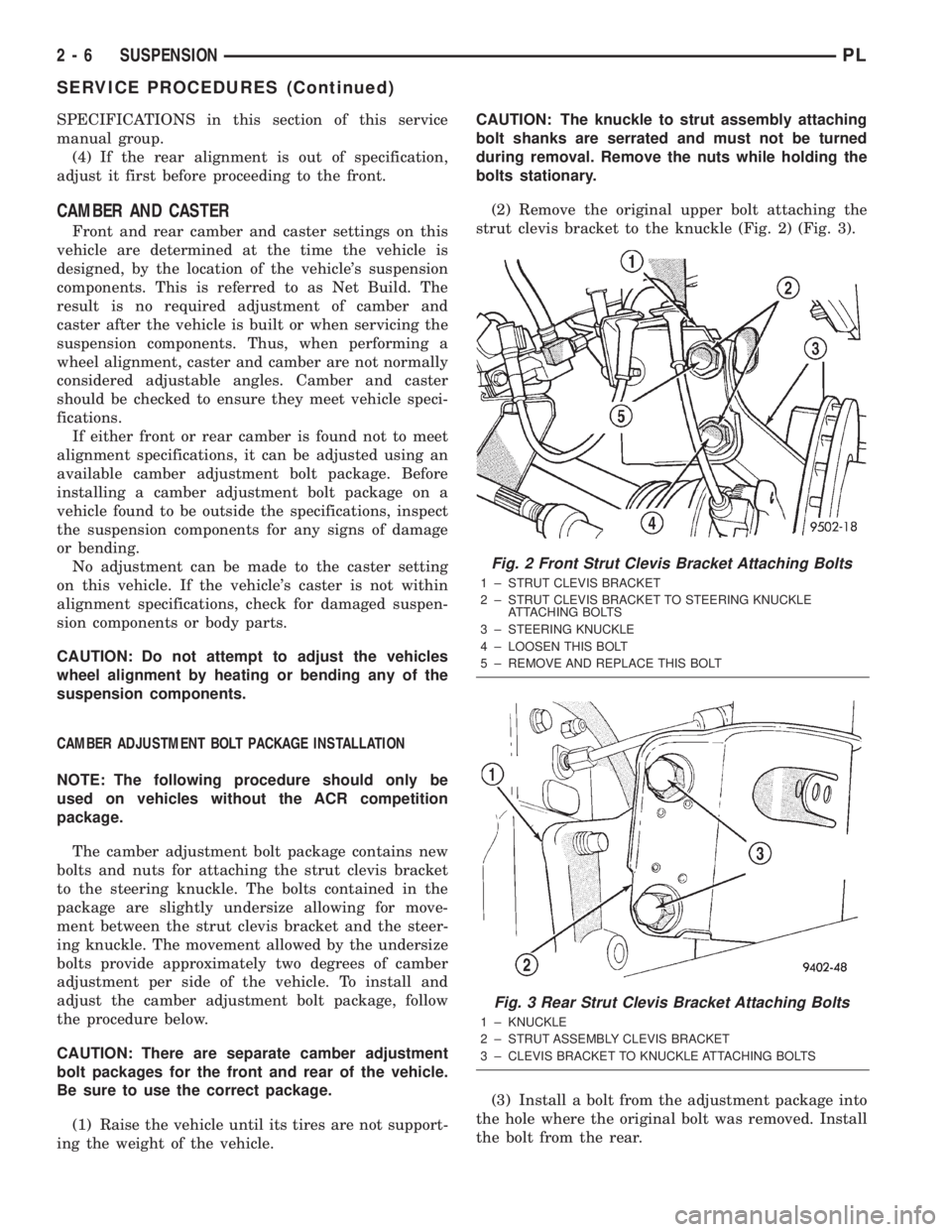
strut clevis bracket to the knuckle (Fig. 2) (Fig. 3).
(3) Install a bolt from the adjustment package into
the hole where the original bolt was removed. Install
the bolt from the rear.
Fig. 2 Front Strut Clevis Bracket Attaching Bolts
1 ± STRUT CLEVIS BRACKET
2 ± STRUT CLEVIS BRACKET TO STEERING KNUCKLE
ATTACHING BOLTS
3 ± STEERING KNUCKLE
4 ± LOOSEN THIS BOLT
5 ± REMOVE AND REPLACE THIS BOLT
Fig. 3 Rear Strut Clevis Bracket Attaching Bolts
1 ± KNUCKLE
2 ± STRUT ASSEMBLY CLEVIS BRACKET
3 ± CLEVIS BRACKET TO KNUCKLE ATTACHING BOLTS
2 - 6 SUSPENSIONPL
SERVICE PROCEDURES (Continued)
Page 18 of 1285
(4) Install a nut provided in adjustment package
on the replacement bolt. Tighten the nut until it's
snug, but still allowing the knuckle to slide in the
clevis bracket.
(5) Remove the original lower bolt.
(6) Install a bolt from the adjustment package into
the bottom hole of the strut clevis bracket. Install the
bolt from the rear.
(7) Install a nut provided in adjustment package
on the replacement bolt. Tighten the nut until it's
snug.
(8) Reinstall the tire and wheel assembly.
(9) Perform the above procedure to any of the
remaining struts as required.
(10) Lower the vehicle and jounce the front and
rear of the vehicle.
(11) Adjust the front or rear camber to the pre-
ferred setting by pushing or pulling on the top of the
tire. When camber is set to specifications, tighten the
upper and lower strut clevis bracket bolts. Again
jounce the front and rear of the vehicle, then verify
the camber settings.
(12) Torque front strut clevis bracket-to-steering
knuckle attaching bolts to 53 N´m (40 ft. lbs.), plus
an additional 1/4 turn after the torque is met. Torque
the rear strut clevis bracket-to-rear knuckle attach-
ing bolts to 95 N´m (70 ft. lbs.).
(13) Once camber is within specifications, adjust
toe to meet the preferred specification setting. Refer
to TOE within this wheel alignment service proce-
dure.
TOE
(1) Center the steering wheel and lock it in place
using a steering wheel clamp.
NOTE: When performing the toe setting procedure,
make sure the rear toe is set to the preferred spec-
ification before setting the front toe to the preferred
specification.
REAR TOE
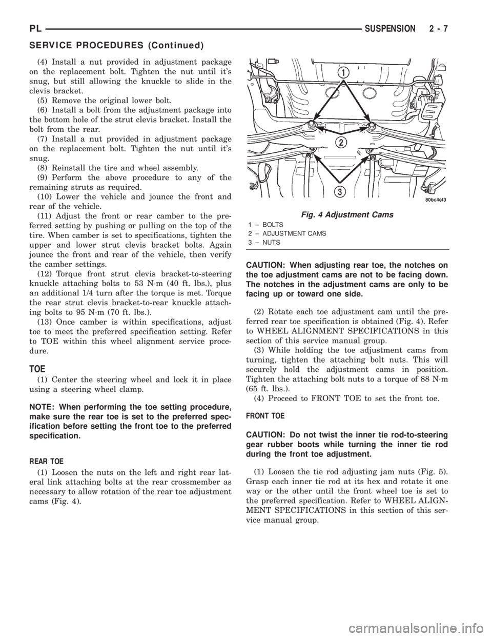
(1) Loosen the nuts on the left and right rear lat-
eral link attaching bolts at the rear crossmember as
necessary to allow rotation of the rear toe adjustment
cams (Fig. 4).CAUTION: When adjusting rear toe, the notches on
the toe adjustment cams are not to be facing down.
The notches in the adjustment cams are only to be
facing up or toward one side.
(2) Rotate each toe adjustment cam until the pre-
ferred rear toe specification is obtained (Fig. 4). Refer
to WHEEL ALIGNMENT SPECIFICATIONS in this
section of this service manual group.
(3) While holding the toe adjustment cams from
turning, tighten the attaching bolt nuts. This will
securely hold the adjustment cams in position.
Tighten the attaching bolt nuts to a torque of 88 N´m
(65 ft. lbs.).
(4) Proceed to FRONT TOE to set the front toe.
FRONT TOE
CAUTION: Do not twist the inner tie rod-to-steering
gear rubber boots while turning the inner tie rod
during the front toe adjustment.
(1) Loosen the tie rod adjusting jam nuts (Fig. 5).
Grasp each inner tie rod at its hex and rotate it one
way or the other until the front wheel toe is set to
the preferred specification. Refer to WHEEL ALIGN-
MENT SPECIFICATIONS in this section of this ser-
vice manual group.
Fig. 4 Adjustment Cams
1 ± BOLTS
2 ± ADJUSTMENT CAMS
3 ± NUTS
PLSUSPENSION 2 - 7
SERVICE PROCEDURES (Continued)
Page 22 of 1285
For more information on the description and oper-
ation of an individual component, refer to the appli-
cable component heading in this section.
STRUT ASSEMBLY (FRONT)
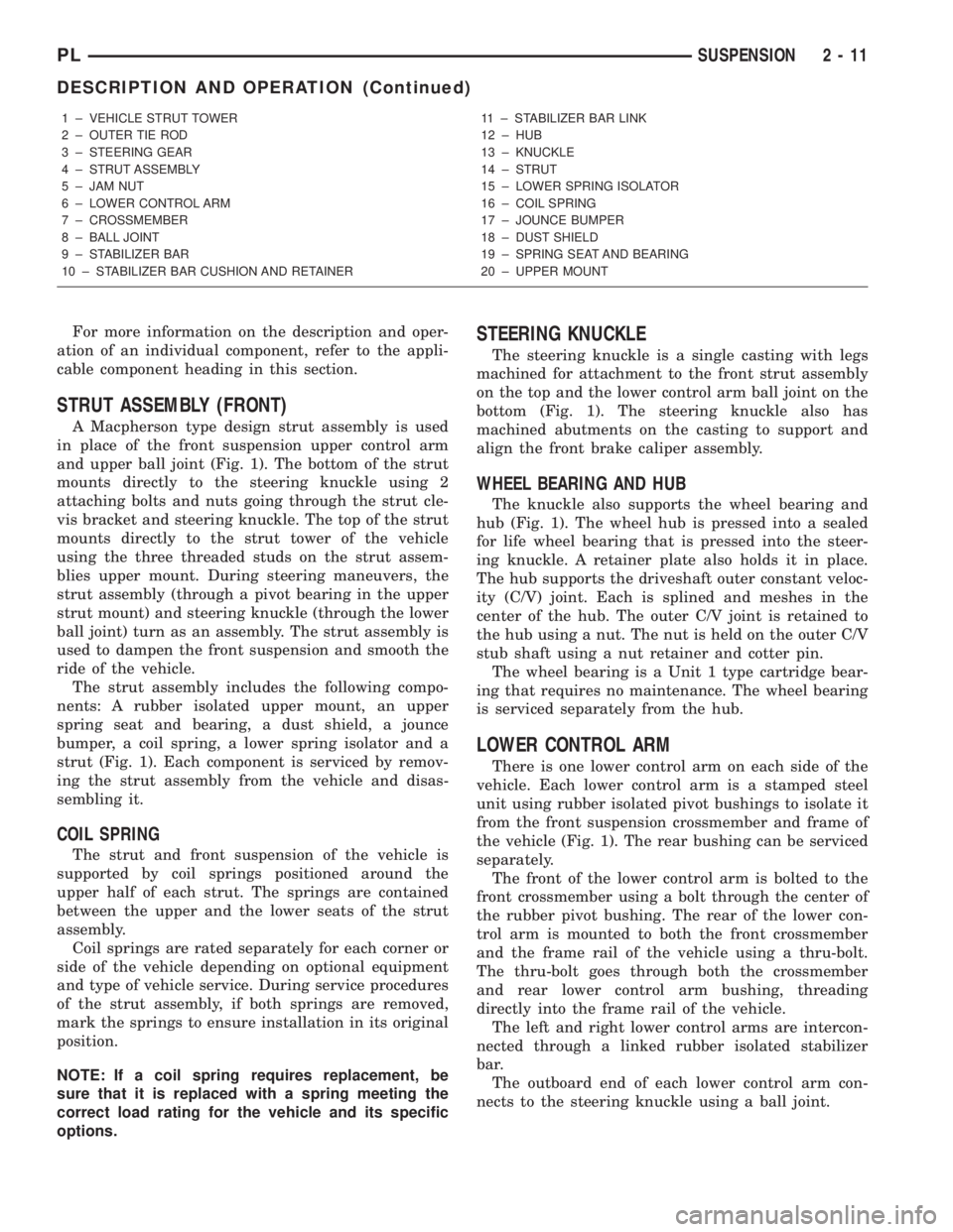
A Macpherson type design strut assembly is used
in place of the front suspension upper control arm
and upper ball joint (Fig. 1). The bottom of the strut
mounts directly to the steering knuckle using 2
attaching bolts and nuts going through the strut cle-
vis bracket and steering knuckle. The top of the strut
mounts directly to the strut tower of the vehicle
using the three threaded studs on the strut assem-
blies upper mount. During steering maneuvers, the
strut assembly (through a pivot bearing in the upper
strut mount) and steering knuckle (through the lower
ball joint) turn as an assembly. The strut assembly is
used to dampen the front suspension and smooth the
ride of the vehicle.
The strut assembly includes the following compo-
nents: A rubber isolated upper mount, an upper
spring seat and bearing, a dust shield, a jounce
bumper, a coil spring, a lower spring isolator and a
strut (Fig. 1). Each component is serviced by remov-
ing the strut assembly from the vehicle and disas-
sembling it.
COIL SPRING
The strut and front suspension of the vehicle is
supported by coil springs positioned around the
upper half of each strut. The springs are contained
between the upper and the lower seats of the strut
assembly.
Coil springs are rated separately for each corner or
side of the vehicle depending on optional equipment
and type of vehicle service. During service procedures
of the strut assembly, if both springs are removed,
mark the springs to ensure installation in its original
position.
NOTE: If a coil spring requires replacement, be
sure that it is replaced with a spring meeting the
correct load rating for the vehicle and its specific
options.
STEERING KNUCKLE
The steering knuckle is a single casting with legs
machined for attachment to the front strut assembly
on the top and the lower control arm ball joint on the
bottom (Fig. 1). The steering knuckle also has
machined abutments on the casting to support and
align the front brake caliper assembly.
WHEEL BEARING AND HUB
The knuckle also supports the wheel bearing and
hub (Fig. 1). The wheel hub is pressed into a sealed
for life wheel bearing that is pressed into the steer-
ing knuckle. A retainer plate also holds it in place.
The hub supports the driveshaft outer constant veloc-
ity (C/V) joint. Each is splined and meshes in the
center of the hub. The outer C/V joint is retained to
the hub using a nut. The nut is held on the outer C/V
stub shaft using a nut retainer and cotter pin.
The wheel bearing is a Unit 1 type cartridge bear-
ing that requires no maintenance. The wheel bearing
is serviced separately from the hub.
LOWER CONTROL ARM
There is one lower control arm on each side of the
vehicle. Each lower control arm is a stamped steel
unit using rubber isolated pivot bushings to isolate it
from the front suspension crossmember and frame of
the vehicle (Fig. 1). The rear bushing can be serviced
separately.
The front of the lower control arm is bolted to the
front crossmember using a bolt through the center of
the rubber pivot bushing. The rear of the lower con-
trol arm is mounted to both the front crossmember
and the frame rail of the vehicle using a thru-bolt.
The thru-bolt goes through both the crossmember
and rear lower control arm bushing, threading
directly into the frame rail of the vehicle.
The left and right lower control arms are intercon-
nected through a linked rubber isolated stabilizer
bar.
The outboard end of each lower control arm con-
nects to the steering knuckle using a ball joint.
1 ± VEHICLE STRUT TOWER
2 ± OUTER TIE ROD
3 ± STEERING GEAR
4 ± STRUT ASSEMBLY
5 ± JAM NUT
6 ± LOWER CONTROL ARM
7 ± CROSSMEMBER
8 ± BALL JOINT
9 ± STABILIZER BAR
10 ± STABILIZER BAR CUSHION AND RETAINER11 ± STABILIZER BAR LINK
12 ± HUB
13 ± KNUCKLE
14 ± STRUT
15 ± LOWER SPRING ISOLATOR
16 ± COIL SPRING
17 ± JOUNCE BUMPER
18 ± DUST SHIELD
19 ± SPRING SEAT AND BEARING
20 ± UPPER MOUNT
PLSUSPENSION 2 - 11
DESCRIPTION AND OPERATION (Continued)
Page 23 of 1285
BALL JOINT
The lower control arm connects to the steering
knuckle through a ball joint mounted at the outboard
end of the arm (Fig. 1). The ball joint is pressed into
the lower control arm and has a non-tapered stud
with a notch for steering knuckle pinch bolt clear-
ance. The ball joint stud is clamped and locked to the
steering knuckle lower leg using a pinch bolt.
The ball joint is lubricated for life during the man-
ufacturing process. Once lubricated for life, the
grease fitting head is snapped off by the manufac-
turer. This is done to eliminate the possibility of
lubrication later in the ball joints life thus damaging
the non-vented ball joint seal boot.
The ball joint used on this vehicle is replaceable
and, if found defective, can be serviced as a separate
component of the lower control arm.
STABILIZER BAR (FRONT)
The stabilizer bar helps control vehicle body roll.
Jounce and rebound movements affecting one wheel
are partially transmitted to the opposite wheel of the
vehicle to stabilize body roll.
The stabilizer bar interconnects both front lower
control arms of the vehicle and is attached to the
front suspension crossmember (Fig. 1).
Attachment of the stabilizer bar to the front sus-
pension crossmember is through 2 rubber-isolator
cushion and retainers (Fig. 1). The stabilizer bar
attachment to the lower control arm is done by uti-
lizing an isolated stabilizer bar link at each arm. All
components of the stabilizer bar are serviceable.
DIAGNOSIS AND TESTING
STRUT ASSEMBLY (FRONT)
Inspect the strut assembly for the following condi-
tions (Fig. 3):
²Inspect for a damaged or broken coil spring.
²Inspect for a torn or damaged strut assembly
dust shield.²Lift the dust shield and inspect the strut assem-
bly for evidence of fluid running from the upper end
of the strut fluid reservoir. (Actual leakage will be a
stream of fluid running down the side and dripping
off lower end of unit.) A slight amount of seepage
between the strut shaft and strut shaft seal is not
unusual and does not affect performance of the strut
assembly.
²Lift the dust shield and inspect the jounce
bumper for signs of damage or deterioration.
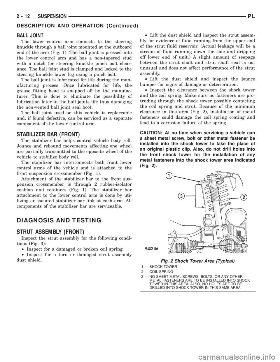
²Inspect the clearance between the shock tower
and the coil spring. Make sure no fasteners are pro-
truding through the shock tower possibly contacting
the coil spring and strut. Because of the minimum
clearance in this area (Fig. 2), installation of metal
fasteners could damage the coil spring coating and
lead to a corrosion failure of the spring.
CAUTION: At no time when servicing a vehicle can
a sheet metal screw, bolt or other metal fastener be
installed into the shock tower to take the place of
an original plastic clip. Also, do not drill holes into
the front shock tower for the installation of any
metal fasteners into the shock tower area indicated
(Fig. 2).
Fig. 2 Shock Tower Area (Typical)
1 ± SHOCK TOWER
2 ± COIL SPRING
3 ± NO SHEET METAL SCREWS, BOLTS, OR ANY OTHER
METAL FASTENERS ARE TO BE INSTALLED INTO SHOCK
TOWER IN THIS AREA. ALSO, NO HOLES ARE TO BE
DRILLED INTO SHOCK TOWER IN THIS SAME AREA.
2 - 12 SUSPENSIONPL
DESCRIPTION AND OPERATION (Continued)
Page 25 of 1285
CAUTION: No attempt should be made to service
the headless grease fitting on the ball joint. It has
been purposely snapped off by the manufacturer to
avoid over-greasing.
STABILIZER BAR (FRONT)
Inspect for broken, cracked or distorted stabilizer
bar cushions and retainers. Inspect for worn or dam-
aged stabilizer bar links (Fig. 1).
SERVICE PROCEDURES
LUBRICATION
There are no serviceable lubrication points on the
front suspension. The front lower ball joints have
grease fittings which have had the head snapped off
by the manufacturer after they have been filled. This
has been done to eliminate the possibility of damag-
ing the non-vented seals. Grease will not leak from
the broken grease fittings. The ball joints are sealed
for life and require no maintenance.
CAUTION: No attempt should be made to replace
the ball joint grease fitting with a new fitting, then
filling the ball joint with grease. Damage to the
grease seal can result.
REMOVAL AND INSTALLATION
SERVICE WARNINGS AND CAUTIONS
WARNING: DO NOT REMOVE THE STRUT SHAFT
NUT WHILE STRUT ASSEMBLY IS INSTALLED IN
VEHICLE, OR BEFORE THE COIL SPRING IS COM-
PRESSED WITH A COMPRESSION TOOL. THE
SPRING IS HELD UNDER HIGH PRESSURE.
CAUTION: Only frame contact hoisting equipment
can be used on this vehicle. All vehicles have a
fully independent rear suspension. The vehicles
cannot be hoisted using equipment designed to lift
a vehicle by the rear axle. If this type of hoisting
equipment is used, damage to rear suspension
components will occur.
CAUTION: At no time when servicing a vehicle can
a sheet metal screw, bolt, or other metal fastener be
installed in the shock tower to take the place of an
original plastic clip. It may come into contact with
the strut or coil spring.CAUTION: Wheel bearing damage will result if after
loosening the hub nut, the vehicle is rolled on the
ground or the weight of the vehicle is allowed to be
supported by the tires for a length of time.
STRUT ASSEMBLY (FRONT)
NOTE: Before proceeding with this procedure,
review SERVICE WARNINGS AND CAUTIONS at the
beginning of REMOVAL AND INSTALLATION in this
section.
REMOVAL
(1) Raise the vehicle. Refer to HOISTING in the
LUBRICATION AND MAINTENANCE group for the
proper lifting procedure.
(2) Remove tire and wheel assembly from location
on front of vehicle requiring strut removal.
(3) If both strut assemblies are to be removed,
mark the strut assemblies right or left according to
which side of the vehicle they were removed from.
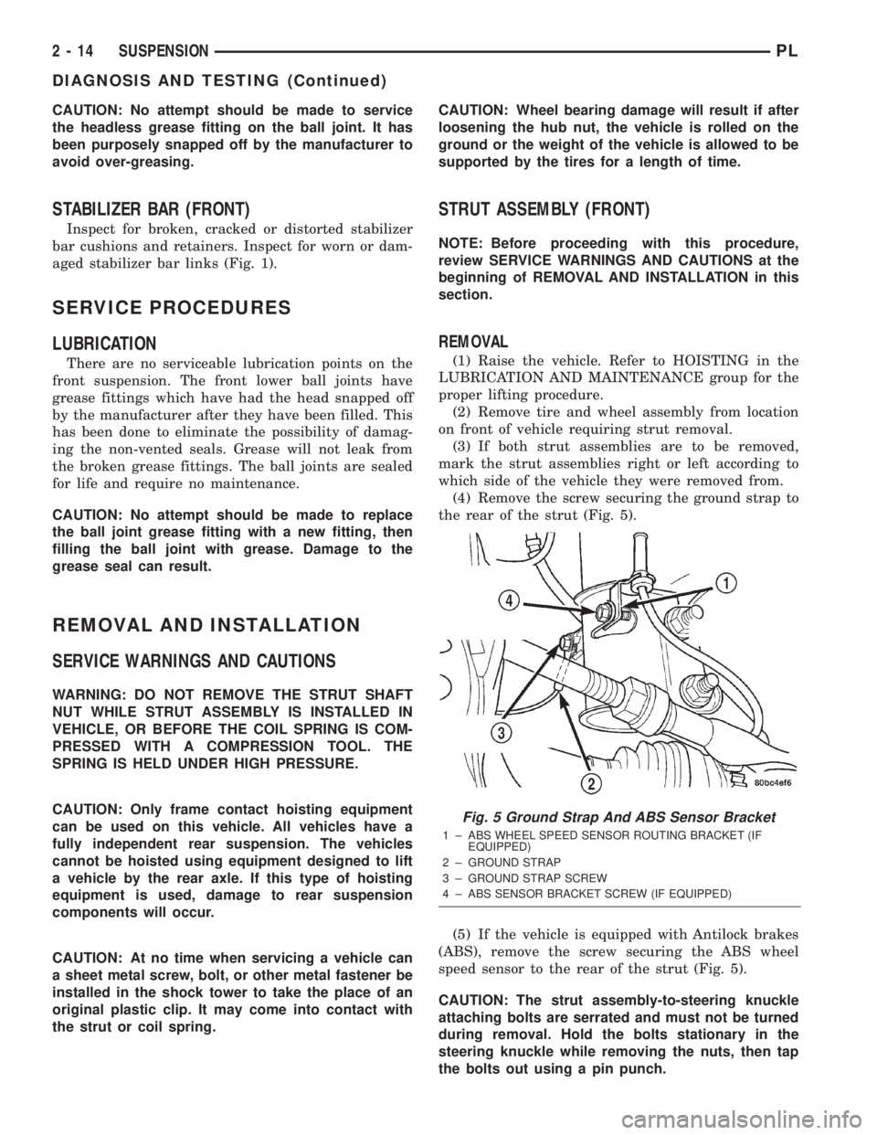
(4) Remove the screw securing the ground strap to
the rear of the strut (Fig. 5).
(5) If the vehicle is equipped with Antilock brakes
(ABS), remove the screw securing the ABS wheel
speed sensor to the rear of the strut (Fig. 5).
CAUTION: The strut assembly-to-steering knuckle
attaching bolts are serrated and must not be turned
during removal. Hold the bolts stationary in the
steering knuckle while removing the nuts, then tap
the bolts out using a pin punch.
Fig. 5 Ground Strap And ABS Sensor Bracket
1 ± ABS WHEEL SPEED SENSOR ROUTING BRACKET (IF
EQUIPPED)
2 ± GROUND STRAP
3 ± GROUND STRAP SCREW
4 ± ABS SENSOR BRACKET SCREW (IF EQUIPPED)
2 - 14 SUSPENSIONPL
DIAGNOSIS AND TESTING (Continued)
Page 26 of 1285
(6) Remove the two bolts attaching the strut to the
steering knuckle (Fig. 1).
(7) Lower the vehicle just enough to open the
hood, but without letting the tires touch the floor.
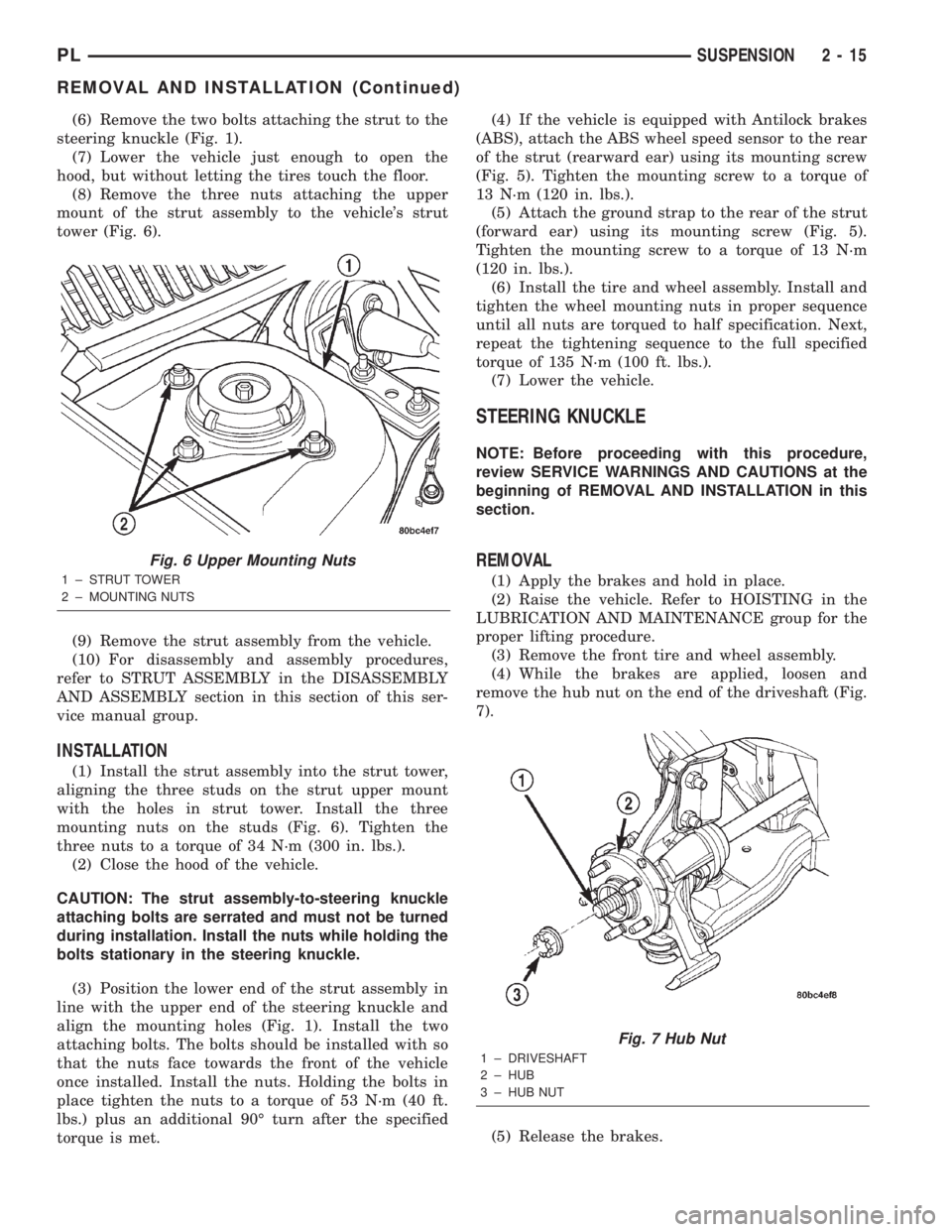
(8) Remove the three nuts attaching the upper
mount of the strut assembly to the vehicle's strut
tower (Fig. 6).
(9) Remove the strut assembly from the vehicle.
(10) For disassembly and assembly procedures,
refer to STRUT ASSEMBLY in the DISASSEMBLY
AND ASSEMBLY section in this section of this ser-
vice manual group.
INSTALLATION
(1) Install the strut assembly into the strut tower,
aligning the three studs on the strut upper mount
with the holes in strut tower. Install the three
mounting nuts on the studs (Fig. 6). Tighten the
three nuts to a torque of 34 N´m (300 in. lbs.).
(2) Close the hood of the vehicle.
CAUTION: The strut assembly-to-steering knuckle
attaching bolts are serrated and must not be turned
during installation. Install the nuts while holding the
bolts stationary in the steering knuckle.
(3) Position the lower end of the strut assembly in
line with the upper end of the steering knuckle and
align the mounting holes (Fig. 1). Install the two
attaching bolts. The bolts should be installed with so
that the nuts face towards the front of the vehicle
once installed. Install the nuts. Holding the bolts in
place tighten the nuts to a torque of 53 N´m (40 ft.
lbs.) plus an additional 90É turn after the specified
torque is met.(4) If the vehicle is equipped with Antilock brakes
(ABS), attach the ABS wheel speed sensor to the rear
of the strut (rearward ear) using its mounting screw
(Fig. 5). Tighten the mounting screw to a torque of
13 N´m (120 in. lbs.).
(5) Attach the ground strap to the rear of the strut
(forward ear) using its mounting screw (Fig. 5).
Tighten the mounting screw to a torque of 13 N´m
(120 in. lbs.).
(6) Install the tire and wheel assembly. Install and
tighten the wheel mounting nuts in proper sequence
until all nuts are torqued to half specification. Next,
repeat the tightening sequence to the full specified
torque of 135 N´m (100 ft. lbs.).
(7) Lower the vehicle.
STEERING KNUCKLE
NOTE: Before proceeding with this procedure,
review SERVICE WARNINGS AND CAUTIONS at the
beginning of REMOVAL AND INSTALLATION in this
section.
REMOVAL
(1) Apply the brakes and hold in place.
(2) Raise the vehicle. Refer to HOISTING in the
LUBRICATION AND MAINTENANCE group for the
proper lifting procedure.
(3) Remove the front tire and wheel assembly.
(4) While the brakes are applied, loosen and
remove the hub nut on the end of the driveshaft (Fig.
7).
(5) Release the brakes.
Fig. 6 Upper Mounting Nuts
1 ± STRUT TOWER
2 ± MOUNTING NUTS
Fig. 7 Hub Nut
1 ± DRIVESHAFT
2 ± HUB
3 ± HUB NUT
PLSUSPENSION 2 - 15
REMOVAL AND INSTALLATION (Continued)
Page 27 of 1285
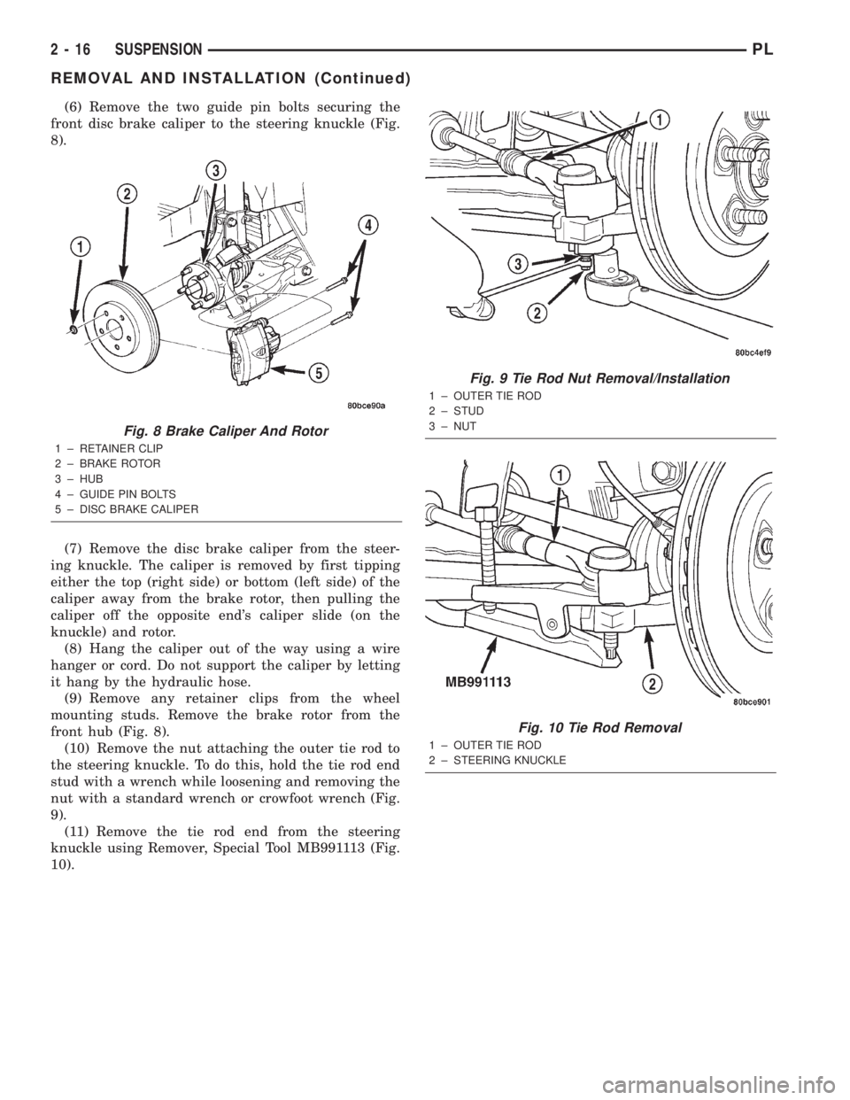
(6) Remove the two guide pin bolts securing the
front disc brake caliper to the steering knuckle (Fig.
8).
(7) Remove the disc brake caliper from the steer-
ing knuckle. The caliper is removed by first tipping
either the top (right side) or bottom (left side) of the
caliper away from the brake rotor, then pulling the
caliper off the opposite end's caliper slide (on the
knuckle) and rotor.
(8) Hang the caliper out of the way using a wire
hanger or cord. Do not support the caliper by letting
it hang by the hydraulic hose.
(9) Remove any retainer clips from the wheel
mounting studs. Remove the brake rotor from the
front hub (Fig. 8).
(10) Remove the nut attaching the outer tie rod to
the steering knuckle. To do this, hold the tie rod end
stud with a wrench while loosening and removing the
nut with a standard wrench or crowfoot wrench (Fig.
9).
(11) Remove the tie rod end from the steering
knuckle using Remover, Special Tool MB991113 (Fig.
10).
Fig. 8 Brake Caliper And Rotor
1 ± RETAINER CLIP
2 ± BRAKE ROTOR
3 ± HUB
4 ± GUIDE PIN BOLTS
5 ± DISC BRAKE CALIPER
Fig. 9 Tie Rod Nut Removal/Installation
1 ± OUTER TIE ROD
2 ± STUD
3 ± NUT
Fig. 10 Tie Rod Removal
1 ± OUTER TIE ROD
2 ± STEERING KNUCKLE
2 - 16 SUSPENSIONPL
REMOVAL AND INSTALLATION (Continued)